Copyrights and trademarks. RM-8000B is a trademark of the TOPCON
Corporation. ... q TOPCON is not responsible for any modifications due to
disassembly.
ENGLISH
AUTO REFRACTOMETER RM-8000B
UNPACKING INSTRUCTIONS
Auto Refractometer RM-8000B
Note:
1
As the main body and the power supply unit are connected by a cable, remove them together carefully from the box, so that they do not become separated.
Open the top lids and take out the following items. ● Chin rest tissue pin ● Chin rest tissue ● Silicon cloth ● Dust cover ● Fuse (spare) ● Model eye ● Power cable ● Printer paper ● Screwdriver ● Reel cover
2
Unpacking instructions
2
Remove the clips and take off the outer carton.
3
Open the inner packaging right and left and take out the main body.
inner packaging
4 Note:
Place the main body on a table or a flat surface. If you are using the automatic table top, there is a hole through which to lead the power cord in the middle of the table. Lead the cord through this hole first.
3
Auto Refractometer RM-8000B
5
Remove the polystyrene foam.
Packaging sponge piece
Sponge
Control lever
Styrofoam
Cushion
a Remove the right-hand styrofoam, viewed from the monitor TV side. b Move the main body to the right, and remove the right sponge. c Lift the control lever a little, and take off the styrofoam from under the base in the direction o f the arrow. d Wipe off the dust from the sliding plate (grey plastic plate) using a cloth or something similar. e Raise the main body by rotating the control lever, and remove the sponge pieces. f
Remove the tapes from the clamping knob, printer cover and switches.
g Remove the air cap from the chin rest. h Viewed from the chin rest side, remove the right transportation clamp (B) using a screwdriver. i
4
Move the main body to the left, and remove the right transportation clamp (A). * The clamps are not necessary any more.
Unpacking instructions
j
Note:
Fasten the rail cover with small screws (C) that were used for fixing it.
To avoid problems, be sure to fully remove the cushions, before applying the power source.
5
Auto Refractometer RM-8000B
6
Checking base movements. Check the base for smooth movement, while operating the control lever.
7
Setting the chin rest tissue. Place and set the chin rest tissue on chin rest tissue pins.
6
TOPCON CORPORATION 75-1 Hasunuma-cho, Itabashi-ku, Tokyo, 174 Japan Phone: 3-3558-2520 Fax: 3-3960-4214
TOPCON EUROPE B.V. Esse Baan 11, 2908 LJ Capelle a/d IJssel, THE NETHERLANDS. Phone: 10-4585077 Fax: 10-4585045
TOPCON S.A.R.L. HEAD OFFICE 104/106, Rue Rivay 92300 Levallois-Perret, FRANCE. Phone: 01-41069494 Fax: 01-47390251 LYON OFFICE 138, Avenue du 8 Mai 1945, 69100 Villeurbanne, France Phone: 78688237 Fax: 78681902
TOPCON DEUTSCHLAND G.M.B.H. Halskestr. 7, 47877 Willich GERMANY. Phone: 02154-9290 Fax: 02154-929-111 C-Point Baden-Würtemberg Gutenbergstaße 10, 73274 Notzingen GERMANY Phone: 07021-974411 Fax: 07021-974421 C-Point Bayern Karl-Benz-Straße 15, 85221 Dachau GERMANY Phone: 08131-321790 Fax: 08131- 321787
TOPCON ESPAÑA S.A. HEAD OFFICE Frederic Mompou, 5 Edificio Euro 3 08960, Sant Just Desvern Barcelona SPAIN Phone: 3-4734057 Fax: 3-4733932
Printed in The Netherlands November 3, 1998 TOPCON-029-UK-1198-02
MADRID OFFICE Avenida Ciudad de Barcelona 81, 28007, Madrid SPAIN Phone: 1-552-4160 Fax: 1-552-4161
TOPCON SCANDINAVIA A. B. Industrivägen 4 / P. O. Box 2140 43302 Sävedalen SWEDEN Phone: 031-261250 Fax: 031-268607 TOPCON TÖNSBERG Ramdalsveien 6 / PO Box 448 Sentrum 3101 Tönsberg NORGE Phone: 00747-33323500 Fax: 00747-33323501 TOPCON DANMARK Ringstedvej 125 4000 Roskilde DANMARK Phone: +45 46327500 Fax: +45 46327555
TOPCON GREAT BRITAIN Topcon House Kennet Side Bone Lane / Newburry Berks RG14 5PX UNITED KINGDOM Phone: 01-635551120 Fax: 01-635551170
ENGLISH
INSTRUCTION MANUAL
AUTO REFRACTOMETER
RM-8000B
Copyrights and trademarks RM-8000B is a trademark of the TOPCON Corporation. © TOPCON 1998
INTRODUCTION
Thank you very much for purchasing the TOPCON Auto Refractometer RM-8000B. To obtain the best results from the instrument, please read the instructions carefully and store the manual in a convenient place for future reference.
Auto Refractometer RM-8000B
Precautions
● This is a precision instrument which needs to be used and kept in
● ● ●
● ●
● ● ● ● ● ● ●
iv
places under normal life conditions regarding temperature and humidity. Do not expose the instrument to direct sunlight. Never install this instrument on an uneven or loose floor. Connect all (power) cords securely before operating. Always keep the area in which the instrument is to be installed clean. Switch off the power, replace the measuring window cap and cover the instrument with a dust cover, when not in use. Never clean the body with chemical solutions, as it may discolour and otherwise cause damage to the instrument. To ensure accurate reading, take care not to soil the measuring window. Do not touch the measuring nozzle other than when cleaning. When operating the unit, do not let the equipment touch the patient’s eyes or nose. Be sure to set the safety stopper. When setting the safety stopper, do not let the instrument touch the patient’s eyes or nose. When operating the chin rest vertical handle, be careful not to pinch the patient’s hand. Handle the equipment with care when moving so that it does not drop or fall over. If the unit should produce smoke, turn the power switch OFF, remove the power cord, and contact your sales agent. TOPCON is not responsible for any modifications due to disassembly nor adjustments made by unauthorised dealer or persons. Contact your authorised dealer or TOPCON directly if any trouble occurs.
Introduction
Selecting externally connected equipment The TOPCON RM-8000B complies with the CE marking. Before connecting a personal computer or bar-code reader to the TOPCON product, make sure that such external equipment is in compliance with the CE making.
Displays for safe use Important warnings are placed on the products and inserted in the instruction manuals, in order to encourage the safe use of products and prevent any danger to the operator and others or damage to existing facilities. We advise that everyone understands the meaning of the following displays and icons before reading the "Safety precautions" and text.
Meaning of displays
Display
Meaning
Ignoring or disregarding this display may result in serious injury or lead to life-threatening situations. WARNING
Ignoring or disregarding this display may lead to personal injury or severe damage to the instrument or facilities. CAUTION ● Injury potential includes hurt, burn, electric shock, etc. ● Damage to facilities refers to extensive damage to buildings,
equipment and furniture.
INSTRUCTION MANUAL
v
Auto Refractometer RM-8000B
Meaning of icons
Icons
Meaning This indicates Hazard Alert (Warning). Specific content is expressed with words or an image, located close to the icon. This icon indicates Prohibition. Specific content is expressed with words or an image, located close to the icon. This indicates Mandatory Action. Specific content is expressed with words or an image, located close to the icon.
Safety precautions This instruction manual specifies safety precautions necessary to prevent accidents. Always observe these cautions and use the instrument correctly.
WARNING Icons
Prevention item
Page
● Electrical shock may cause burns or possible fire. Turn
the main power switch OFF and UNPLUG the power cord before replacing fuses. Replace only with fuses of the correct rating.
64
● To avoid electrical shock, do not open the instrument.
Refer all servicing to only qualified personnel.
vi
-
Introduction
WARNING Icons
Prevention item
Page
● To avoid electrical shock, do not remove covers from the
bottom and top surfaces, monitor screen, measuring unit, etc.
● Do not insert or drop metals into the ventilation holes or
clearances. Such actions may invoke electric shock.
-
● To avoid electrical shock, do not connect or disconnect
the power plug with wet hands.
-
● Keep this instrument away from water or other liquids.
A fire or electric shock may otherwise occur.
-
● Avoid the presence of water-filled glasses or other
containers in the vicinity. Infiltration of water may lead to a fire or electric shock.
-
● Connect the power plug to a grounded three-pin AC
outlet. Other types of outlets may not allow grounding, possibly causing a fire or electric shock due to short circuits.
-
● Be sure to use a properly rated fuse provided in the
accessory box. Use of other than a properly rated fuse may lead to a fire at the time of a malfunction.
64
● In the event of any conditions such as smoke, turn off the
power switch immediately and disconnect the power plug from the outlet. Continued use in spite of such conditions, may lead to a fire. For repair service, contact your authorised dealer.
INSTRUCTION MANUAL
-
vii
Auto Refractometer RM-8000B
WARNING Icons
Prevention item
Page
● To avoid potential injury, hold the instrument in the
proper position.
25
● To avoid potential injury and/or damage to the
instrument, do not drop the instrument.
25
● To avoid potential injury during operation, do not touch
the patient's eyes or nose with the instrument.
55
● To avoid potential injury, ensure that the safety stopper
knob is engaged prior to use.
55
● To avoid potential injury, keep your fingers away from
the chin rest.
55
● To avoid potential injury, do not put your hands or fingers
under the measuring head when moving the head up and down.
56
● When moving the instrument, be sure to hold It at the
bottom surface with two persons. Single-handed transportation is very dangerous, possibly causing the one who is carrying to hurt his back or become injured if they the drop the instrument. Holding other than the bottom may also pinch the hands and result in dropping the instrument.
viii
25
Introduction
Operation and maintenance Purpose This Auto Refractometer is a piece of precision electrical equipment for medical use, which must be used according to a doctor’s instructions.
User maintenance To ensure the safety and performance of the instrument, the maintenance shall be carried out by a trained service technician only, unless otherwise specified in this manual. The following maintenance tasks, however, can be performed by the user. We refer you to the applicable text in this manual, with regard to the maintenance method. Fuse replacement
Cleaning the examination window
The primary fuse for the main body can be replaced by a non-trained service technician. For details, we refer you to the applicable text in this manual. For details, we refer you to the applicable text in this manual.
Escape clause
● TOPCON shall not take any responsibility for damage due to fire,
earthquakes, actions by third persons and other accidents, or the negligence and misuse by the user and use under unusual conditions. ● TOPCON shall not take any responsibility for damage derived from the inability to use this equipment, such as a loss of business profit and suspension of business. ● TOPCON shall not take any responsibility for damage caused by any other operation than that described in this instruction manual. ● Diagnoses shall be made on the responsibility of the doctors concerned and TOPCON shall not take any responsibility for the results of such diagnoses.
INSTRUCTION MANUAL
ix
Auto Refractometer RM-8000B
Warning indications and positions To ensure safety, warning labels are provided. Use the equipment correctly according to these warning instructions. If any of the following warning labels are missing, please contact us at the address stated on the back cover of this manual.
CAUTION • To avoid potential injury during operation, do not touch the patient's eyes or nose with the instrument.
WARNING • To avoid electrical shock, do not open the instrument. Refer all servicing to only qualified personnel.
WARNING • Electrical shock may cause burns or possibly fire. Turn the main power switch OFF and UNPLUG the power cord before replacing fuses. Replace only with fuses of the correct rating.
x
Contents
INTRODUCTION Precautions Selecting externally connected equipment . . . . . . . . . . . . . . . . . . . . . . . . . . . .
Displays for safe use Meaning of displays . . . . . . . . . . . . . . . . . . . . . . . . . . . . . . . . . . . . . . . . . . . . .
iv v
v v
Safety precautions
vi
Operation and maintenance
ix
Purpose . . . . . . . . . . . . . . . . . . . . . . . . . . . . . . . . . . . . . . . . . . . . . . . . . . . . . . ix User maintenance . . . . . . . . . . . . . . . . . . . . . . . . . . . . . . . . . . . . . . . . . . . . . . . ix
1
Escape clause
ix
Warning indications and positions
x
COMPONENTS 1.1
Body
15
1.2
Control panel
18
1.3
Monitor screen
19
Auto Refractometer RM-8000B
1.4
Print-out
21
1.5
Assembly components
23
2
ASSEMBLY 2.1
Installation
25
2.2
Connecting power cable
27
2.3
Connecting external I/O terminals
28
RS-232C OUT . . . . . . . . . . . . . . . . . . . . . . . . . . . . . . . . . . . . . . . . . . . . . . . . . 28 RS-232C IN . . . . . . . . . . . . . . . . . . . . . . . . . . . . . . . . . . . . . . . . . . . . . . . . . . . 28
2.4
29
2.4.1
INITIAL SET screen . . . . . . . . . . . . . . . . . . . . . . . . . . . . . . . . . . . . . . . . . . . . . . How to set the buzzer . . . . . . . . . . . . . . . . . . . . . . . . . . . . . . . . . . . . . . . . . . . How to set the refractory power . . . . . . . . . . . . . . . . . . . . . . . . . . . . . . . . . . . How to set the monitor screen display . . . . . . . . . . . . . . . . . . . . . . . . . . . . . . How to set the date . . . . . . . . . . . . . . . . . . . . . . . . . . . . . . . . . . . . . . . . . . . . .
30 30 31 31 32
2.4.2
NUMBER SET screen . . . . . . . . . . . . . . . . . . . . . . . . . . . . . . . . . . . . . . . . . . . . How to set the patient number . . . . . . . . . . . . . . . . . . . . . . . . . . . . . . . . . . . . How to display patient number on the monitor screen . . . . . . . . . . . . . . . . . . How to print the patient number . . . . . . . . . . . . . . . . . . . . . . . . . . . . . . . . . . . How to reset the patient number . . . . . . . . . . . . . . . . . . . . . . . . . . . . . . . . . . . How to set the instrument number . . . . . . . . . . . . . . . . . . . . . . . . . . . . . . . . . How to display the instrument number on the monitor screen . . . . . . . . . . . . How to print the instrument number . . . . . . . . . . . . . . . . . . . . . . . . . . . . . . . .
32 33 34 34 35 35 36 36
2.4.3
PRINT OUT screen . . . . . . . . . . . . . . . . . . . . . . . . . . . . . . . . . . . . . . . . . . . . . . How to set the printout format . . . . . . . . . . . . . . . . . . . . . . . . . . . . . . . . . . . . . How to print equivalent spherical power . . . . . . . . . . . . . . . . . . . . . . . . . . . . . How to print computer lens meter data . . . . . . . . . . . . . . . . . . . . . . . . . . . . . . How to print the bar-code . . . . . . . . . . . . . . . . . . . . . . . . . . . . . . . . . . . . . . . .
37 37 38 38 39
2.4.4
ONLINE (data communication) screen . . . . . . . . . . . . . . . . . . . . . . . . . . . . . . . How to set computer lens meter data receiving format . . . . . . . . . . . . . . . . . . How to set RS-232C communication format . . . . . . . . . . . . . . . . . . . . . . . . . . How to set RS-232C communication speed . . . . . . . . . . . . . . . . . . . . . . . . . .
39 40 41 41
2.5
SETTING MENU screen
42
2.5.1
How to set the measurement step . . . . . . . . . . . . . . . . . . . . . . . . . . . . . . . . . . . 43
2.5.2
How to set axial angle step . . . . . . . . . . . . . . . . . . . . . . . . . . . . . . . . . . . . . . . . 44
2.5.3
How to set VD . . . . . . . . . . . . . . . . . . . . . . . . . . . . . . . . . . . . . . . . . . . . . . . . . . 44
2.5.4
How to set continuous measurement . . . . . . . . . . . . . . . . . . . . . . . . . . . . . . . . . 45
2.5.5
How to set data communication . . . . . . . . . . . . . . . . . . . . . . . . . . . . . . . . . . . . . 45
2.5.6
How to set the date/time . . . . . . . . . . . . . . . . . . . . . . . . . . . . . . . . . . . . . . . . . . 46
2.6 2.6.1
xii
INITIAL MENU settings
How to set printer paper
47
Auto setting . . . . . . . . . . . . . . . . . . . . . . . . . . . . . . . . . . . . . . . . . . . . . . . . . . . . 47
Contents
2.6.2
2.7
3
Power Saving System and how to restore
53
BASIC OPERATION 3.1
Measurement
55
3.2
Erasing measurement values
58
3.3
Printout of measurement values
59
3.4
Input/output using RS-232C
60
4
MAINTENANCE 4.1
Daily check-ups
61
4.2
Daily maintenance
62
4.3
Adjusting the monitor screen
62
4.4
Printer paper jam
63
4.5
Fuse change
64
4.6
Cleaning the dust cover
65
4.7
Ordering consumable items
66
4.8
Optional accessories
67
4.8.1
5
6
Manual setting . . . . . . . . . . . . . . . . . . . . . . . . . . . . . . . . . . . . . . . . . . . . . . . . . . 50
Adjustable instrument table AIT-11 . . . . . . . . . . . . . . . . . . . . . . . . . . . . . . . . . . 67
TROUBLESHOOTING 5.1
Messages on the screen during measurement
69
5.2
Troubleshooting table
70
SPECIFICATIONS
73
INSTRUCTION MANUAL
xiii
Auto Refractometer RM-8000B
xiv
1
COMPONENTS
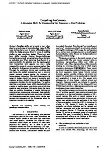
1.1 Body
(1)
(2)
(3) (4) (5) (6) (7)
(9) (8)
Auto Refractometer RM-8000B
(1)
Measuring head
(2)
Monitor screen Displays an image of the patient’s eye, the alignment mark, and the measurement results.
(3)
Measuring button Measuring is accomplished by pressing this button after aligning. When the electricity saving function is working, pressing this button will turn the monitor back on.
(4)
Control lever Tilt it to move the unit forward/backward, left/right and turn it to move up/ down.
(5)
Safety stopper knob To prevent forward/backward, left/right movement. The unit cannot be used when this knob is screwed tight.
(6)
Control panel To set the various system parameters.
(7)
Power lamp Lights up when the power supply is switched ON
(8)
External I/O terminal For the RS-232C cable connection.
(9)
Fixing knob To stop forward/backward, left/right movement.
16
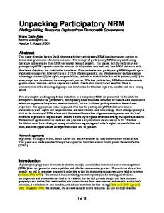
Components
(10)
(11)
(12)
(13)
(14) (15)
(16)
(17)
(10)
Forehead rest Supports the patient’s head.
(11)
Examination window
(12)
Canthus marker Guide for adjusting the height for the patient’s eye.
(13)
Chin rest tissue pins For securing the chin rest tissue, after slotting it into the holes provided.
(14)
Chin rest Supports the patient’s chin.
(15)
Power switch
(16)
Adjusting knobs
(17)
Cap (for examination window)
INSTRUCTION MANUAL
17
Auto Refractometer RM-8000B
1.2 Control panel (18)
(19)
(21) (22) (20) (23)
(24)
(18)
Print button Prints out the screen readings. When not printing out the readings, the paper can be fed by holding down the button.
(19)
Menu button Displays the menu screen.
(20)
IOL button Press this button to make measurements when errors are likely, for example, eyes with IOL.
(21)
Graphic print button Prints out graphically the state of refraction.
(22)
Target image button Allows the operator to observe the stored target image on the monitor screen.
(23)
Fixation target brightness button Changes the brightness of fixation target.
(24)
CYL display selection button Changes the CYL display.
18
Components
1.3 Monitor screen Measuring screen
(25) (30) (26) (31) (27)
(32)
(28)
(33)
(34) (29)
(25)
CYL power symbol
(26)
Target eye
(27)
Instrument No.
(28)
Patient No.
(29)
Typical value
(30)
Fixation target brightness
(31)
Frequency of measurement
(32)
Vertical distance
(33)
Alignment mark
(34)
Smallest measurable pupil diameter mark
INSTRUCTION MANUAL
19
Auto Refractometer RM-8000B
Initial setting screen
Menu setting screen
20
Components
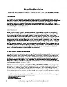
1.4 Print-out
Bar-code
Instrument No.
Work ID No.
Patient No. Instrument No. VD (vertical distance) Cylindrical power mark Right eye measurements
Results of 5 right eye measurements (can be recorded up to 10 measurements) Typical value of right eye (The * mark is displayed when 3 or more measurements are done.) Equivalent spherical power of right eye
The ( ) mark is added when measurement values are not fully reliable. The I mark is displayed in IOL mode. If the reliability is low and values of C and A cannot be determined, ** marks are given to pertaining columns.
PD value
ALL mode (example)
INSTRUCTION MANUAL
21
Auto Refractometer RM-8000B
Note:
22
When measurement is done under the IOL mode, a reliability factor is printed out following the I mark. The reliability factor is formed with integers 1 to 9 in increasing order of reli-ability. Additionally, if the reliability is high enough, the reliability factor is not shown in the printout.
Components
1.5 Assembly components The following items in addition to the RM-8000 instrument body are included
(36) (35)
(38) (37)
(39) (40)
(42)
(41)
(43)
(44)
(45)
INSTRUCTION MANUAL
(46)
23
Auto Refractometer RM-8000B
24
(35)
Power cable (1)
(36)
Printing paper (2 rolls)
(37)
Chin rest tissue pin (spare, 2)
(38)
Chin rest tissue (1 bundle, 500 sheets)
(39)
Fuse (spare, 2)
(40)
Accessory box (1)
(41)
Silicone cloth (1)
(42)
Instruction Manuals (1 set)
(43)
Dust cover (1)
(44)
Rail cover (2)
(45)
Model eye (1)
(46)
Screwdriver (1)
2
ASSEMBLY
2.1 Installation
To avoid potential injury, ensure that the safety stopper knob is engaged prior to use. CAUTION
CAUTION
When moving the instrument, be sure to hold it at the bottom with two people. Single-handed transportation is very dangerous, possibly causing the one who is carrying to hurt his back or become injured if they the drop the instrument. Holding other than the bottom may also pinch the hands and result in dropping the instrument.
To avoid potential injury, hold the instrument in the proper position. CAUTION
Auto Refractometer RM-8000B
1 Fasten the clamp knob. 2 Hold the instrument firmly at the specified position and place it on the automatic instrument table. For the automatic instrument table, see Optional accessories on page 67.
Holding positions
Clamp knob
Holding the instrument
3 After installation, loosen the clamp knob. Now the main body can be moved. 4 If the instrument is not fully level, make fine adjustments by rotating the 4 adjusters. Additionally, do not unscrew adjusters exceeding 1 cm.
Adjuster
26
Assembly
2.2 Connecting power cable
WARNING
Be sure to connect the power plug to a grounded AC 3-pin receptacle. Connection with any other receptacle without grounding it may cause fire and electric shock.
To avoid an electrical shock, do not connect or disconnect the power plug with wet hands. CAUTION
1 Make sure that the power switch of the main body is off. Plug the power cable into the main body.
2 Plug the power cable into a grounded 3-p AC receptacle.
INSTRUCTION MANUAL
27
Auto Refractometer RM-8000B
2.3 Connecting external I/O terminals RS-232C OUT This machine can be connected with a PC (personal computer) using RS-232C. 1 Connect the connection cable to the RS-232C OUT terminal of the main body. 2 Connect the other end of the connection cable to the PC.
IN terminal
OUT terminal Mouse connector
RS-232C IN Also, this machine can be connected with a bar-code reader using RS-232C. 1 Connect the connection cable to the RS-232C IN terminal of the main body. 2 Connect the other end of the connection cable to the external device.
28
Assembly
2.4 INITIAL MENU settings In the default setup, settings such as patient number, instrument number, refractory power shift, RS-232C, auto print, etc. can be specified. Preparation for initial setup
1 Make sure that the power cable is connected. For connection, see Connecting power cable on page 27. 2 To enter the default setting mode, turn the power switch (15) to ON while pressing down the menu button (19), and releasing it when the buzzer beeps. The power lamp (7) will light up and the default settings will appear on the monitor screen, (2) as shown in the display above. Returning to the measuring screen 1 To exit the initial menu mode, press the measuring button (3) and move the cursor towards EXIT. 2 Press the print button (18) ("EXIT OK" is displayed). 3 Press the print button (18) again. (The measuring screen is returned and the set items are printed out.)
Measuring button
INSTRUCTION MANUAL
29
Auto Refractometer RM-8000B
2.4.1
INITIAL SET screen In the INITIAL SET screen, the buzzer sound, refractory power shift, display of typical value in monitor screen and the date can be changed.
1 In the INITIAL MENU screen, make sure that the cursor is on INITIAL SET, and then press the print button (18). The monitor screen is changed to the INITIAL SET screen. 2 Close the INITIAL SET screen and call up the INITIAL MENU screen. 3 Move the cursor to EXIT. 4 Press the print button (18). Note:
To return to the previous item on the screen: While pressing the print button (18), press the measuring button (3).
How to set the buzzer The buzzer sound can be set. Before shipment, it is set to "YES" so that the buzzer sounds by default.
1 On the INITIAL MENU screen, choose INITIAL SET and call up the INITIAL SET screen. 2 Press the print button (18), and choose YES (buzzer sound) or NO (no buzzer sound) for BUZZER. 3 Settings are entered by pressing the measuring button (3), and the cursor then moves on to the next item.
30
Assembly
How to set the refractory power The refractory power (S value) can be shifted. Before shipment, it is set to "+0.37", by default.
1 In the INITIAL MENU screen, choose INITIAL SET and call up the INITIAL SET screen. 2 Press the measuring button (3) and move the cursor to DPTR SHIFT. 3 Pressing the menu button (19) increases the value. Pressing the IOL button (20) decreases the value. Values can be set at 0.12D steps between -1.00D and +1.00D. 4 Press the measuring button (3), and the cursor moves on to the next item.
How to set the monitor screen display The typical value can be displayed in the monitor screen. Before shipment, it is set to "NO" (no display), by default.
1 In the INITIAL MENU screen, choose INITIAL SET and call up the INITIAL SET screen. 2 Press the measuring button (3) and move the cursor on to AVERAGE DISP. 3 Press the print button (18) and choose YES (display in menu screen) or NO (no display in menu screen).
INSTRUCTION MANUAL
31
Auto Refractometer RM-8000B
4 Press the measuring button (3), and the cursor moves on to the next item.
How to set the date The date format of printout can be changed. Before shipment, it is set to "1998.06.01", by default.
1 In the INITIAL MENU screen, choose INITIAL SET and call up the INITIAL SET screen. 2 Press the measuring button (3) and move the cursor on to "DATE". 3 Press the print button (18) and choose: 1998.06.01; JUN. 01. 1998; or 01. JUN. 1998. 4 Press the measuring button (3), and the cursor returns to "EXIT". 5 Press the measuring button (3), and the cursor returns to the first item (BUZZER).
2.4.2
NUMBER SET screen In the NUMBER SET screen, the patient number setting, monitor screen display of patient number, printing patient number, resetting of patient number, instrument number setting, monitor screen display of instrument number and printing instrument number can be changed.
32
Assembly
1 In the INITIAL MENU screen, press the measuring button (3) and move the cursor to NUMBER SET. 2 Press the print button (18), and the monitor screen is changed to the NUMBER SET screen. 3 Close the NUMBER SET screen and call up the INITIAL MENU screen. 4 Move the cursor to EXIT. 5 Press the print button (18). Note:
To return to the previous item on the screen: While pressing the print button(18), press the measuring button (3).
How to set the patient number The patient number can be set between 0 and 9999. Before shipment, it is set to "0001", by default.
1 In the INITIAL MENU screen, choose NUMBER SET and call up the NUMBER SET screen. 2 Press the measuring button (3) and move the cursor to SERIAL NO.. 3 Pressing the menu button (19) increases the value. Pressing the IOL button (20) decreases the value. 4 Press the measuring button (3), and the cursor move on to the next item.
INSTRUCTION MANUAL
33
Auto Refractometer RM-8000B
How to display patient number on the monitor screen The patient number can be displayed on the monitor screen. Before shipment, by default it is set to "YES".
1 In the INITIAL MENU screen, choose NUMBER SET and call up the NUMBER SET screen. 2 Press the measuring button (3) and move the cursor to SERIAL OUT TV. 3 Press the print button (18) and choose YES (display in menu screen) or NO (no display in menu screen). 4 Press the measuring button (3), and the cursor moves on to the next item.
How to print the patient number The patient number can be printed out. Before shipment, by default it is set to "YES" (printout).
1 In the INITIAL MENU screen, choose NUMBER SET and call up the NUMBER SET screen. 2 Press the measuring button (3) and move the cursor to SERIAL OUT PRT. 3 Press the print button (18) and choose YES (printout) or NO (no printout). 4 Press the measuring button (3), and the cursor moves on to the next item.
34
Assembly
How to reset the patient number The patient number can be reset by switching on the power source. Before shipment, by default it is set to "NO" (no reset).
1 In the INITIAL MENU screen, choose NUMBER SET and call up the NUMBER SET screen. 2 Press the measuring button (3) and move the cursor to SERIAL RESET. 3 Press the print button (18) and choose YES (rest) or NO (no reset). 4 Press the measuring button (3), and the cursor moves on to the next item.
How to set the instrument number The instrument number can be set between 0 and 99. Before shipment, it is set to "01" by default.
1 In the INITIAL MENU screen, choose NUMBER SET and call up the NUMBER SET screen. 2 Press the measuring button (3) and move the cursor to RM NO.. 3 Pressing the menu button (19) increases the value. Pressing the IOL button (20) decreases the value. 4 Press the measuring button (3), and the cursor moves on to the next item.
INSTRUCTION MANUAL
35
Auto Refractometer RM-8000B
How to display the instrument number on the monitor screen The instrument number can be displayed in the monitor screen. Before shipment, by default it is set to "NO" (no display).
1 In the INITIAL MENU screen, choose NUMBER SET and call up the NUMBER SET screen. 2 Press the measuring button (3) and move the cursor to RM OUT TV. 3 Press the print button (18) and choose YES (display in menu screen) or NO (no display in menu screen). 4 Press the measuring button (3), and the cursor moves on to the next item.
How to print the instrument number The instrument number can be printed out. Before shipment, by default it is set to "NO" (no printout).
1 In the INITIAL MENU screen, choose NUMBER SET and call up the NUMBER SET screen. 2 Press the measuring button (3) and move the cursor to RM OUT PRT. 3 Press the print button (18) and choose YES (printout) or NO (no printout). 4 Press the measuring button (3), and the cursor moves on to the next item.
36
Assembly
2.4.3
PRINT OUT screen In the PRINT OUT screen, the printout format, printing equivalent spherical power, printing computer lens meter data, and printing bar-code can be changed.
1 In the INITIAL MENU screen, press the measuring button (3) and move the cursor to PRINT OUT. 2 Press the print button (18), and the monitor screen is changed to the PRINT OUT screen. 3 Close the PRINT OUT screen and call up the INITIAL MENU screen. 4 Move the cursor to EXIT. 5 Press the print button (18). Note:
To return to the previous item on the screen: While pressing the print button (18), press the measuring button (3).
How to set the printout format The printout format can be set. Before shipment, by default it is set to "ALL" (print out all data).
1 In the INITIAL MENU screen, choose PRINT OUT and call up the PRINT OUT screen. 2 Press the measuring button (3) and move the cursor to PRINT TYPE.
INSTRUCTION MANUAL
37
Auto Refractometer RM-8000B
3 Press the print button (18) and choose: ALL AVE SIN
(print out all data); (print out date, settings and typical value of refractory power only); or (print out typical value only).
4 Press the measuring button (3), and the cursor moves on to the next item.
How to print equivalent spherical power The equivalent spherical power can be printed. Before shipment, by default it is set to "YES" (printout).
1 In the INITIAL MENU screen, choose PRINT OUT and call up the PRINT OUT screen. 2 Press the measuring button (3) and move the cursor to S.E. DATA. 3 Press the print button (18) and choose YES (printout) or NO (no printout). 4 Press the measuring button (3), and the cursor moves on to the next item.
How to print computer lens meter data Computer lens meter data can be printed. Before shipment, by default it is set to "NO" (no printout).
38
Assembly
1 In the INITIAL MENU screen, choose PRINT OUT and call up the PRINT OUT screen. 2 Press the measuring button (3) and move the cursor to CL PRINT. 3 Press the print button (18) and choose YES (printout) or NO (no printout). 4 Press the measuring button (3), and the cursor moves on to the next item.
How to print the bar-code The bar-code can be printed out. Before shipment, by default it is set to "NO" (no printout).
1 In the INITIAL MENU screen, choose PRINT OUT and call up the PRINT OUT screen. 2 Press the measuring button (3) and move the cursor to BAR PRT. 3 Press the print button (18) and choose YES (printout) or NO (no printout). 4 Press the measuring button (3), and the cursor moves on to the next item.
2.4.4
ONLINE (data communication) screen In the ONLINE screen, the computer lens meter data receiving format, communication format and communication speed can be changed.
INSTRUCTION MANUAL
39
Auto Refractometer RM-8000B
1 In the INITIAL MENU screen, press the measuring button (3) and move the cursor to ONLINE. 2 Press the print button (18), and the monitor screen is changed to the ONLINE screen. 3 Close the ONLINE screen and call up the INITIAL MENU screen. 4 Move the cursor to EXIT. 5 Press the print button (18). Note:
To return to the previous item on the screen: While pressing the print button (18), press the measuring button (3).
How to set computer lens meter data receiving format The RS-232C format for receiving computer lens meter data can be set. Before shipment, by default it is set to "NO" (no receiving).
1 In the INITIAL MENU screen, choose ONLINE and call up the ONLINE screen. 2 Press the measuring button (3) and move the cursor to "CL INPUT". 3 Press the print button (18) and choose: NO OLD NEW STD1 R-ID W-ID
(no receiving); (OLD RS-232C format); (NEW RS-232C format); (STD1 RS-232C format); (receives patient no. via RS-232C input port for processing as real ID); or (receives patient no. via RS-232C input port for processing as work ID).
4 Press the measuring button (3), and the cursor moves on to the next item.
40
Assembly
How to set RS-232C communication format The RS-232C communication format can be set. Before shipment, by default it is set to "OLD" (old TOPCON format).
1 In the INITIAL MENU screen, choose ONLINE and call up the ONLINE screen. 2 Press the measuring button (3) and move the cursor to RS232C FORM. 3 Press the print button (18) and choose: OLD NEW STD1 ALL CM1 CM2 CM3 CM4 CM5
(OLD RS-232C format); (NEW RS-232C format); (TOPCON STD1 format); (tools mode); (custom specification); (custom specification); (custom specification); (custom specification); or (custom specification).
4 Press the measuring button (3), and the cursor moves on to the next item.
How to set RS-232C communication speed The RS-232C communication speed can be set. Before shipment, by default it is set to "2400" (baudrate 2400).
INSTRUCTION MANUAL
41
Auto Refractometer RM-8000B
1 In the INITIAL MENU screen, choose ONLINE and call up the ONLINE screen. 2 Press the measuring button (3) and move the cursor to "BAUD-RATE". 3 Press the print button (18) and choose: 2400 (baud rate 2400); or 9600 (baud rate 9600. 4 Press the measuring button (3), and the cursor moves on to the next item.
2.5 SETTING MENU screen In the menu setup, the data step, contact/glasses, continuous measurement, RS-232C, ADD, date and time can be set. Preparation for menu setting 1 Make sure the power cable is connected. For connection, see Connecting power cable on page 27. 2 Press ON the power switch. How to display the MENU screen
1 Make sure you are in the measuring screen. 2 Press the menu button (19) of the control panel. Make sure you are in the SETTING MENU screen.
42
Assembly
Returning to the measurement screen
Press the measuring button (3), select EXIT, and press print button (18).
2.5.1
How to set the measurement step The measurement step can be selected from 0.12, 0.25. Before shipment, by default it is set to "0.25".
1 Press the menu button (19) of the control panel and call up the SETTING MENU screen. STEP is highlighted, and measurement steps are displayed on the right with the set step highlighted. 2 Press the print button (18) and select the required measurement step. 3 Press the measuring button (3). The setup is complete, and the next item (AXIS STEP) is highlighted.
INSTRUCTION MANUAL
43
Auto Refractometer RM-8000B
2.5.2
How to set axial angle step The axial angle step can be selected from 1 and 5. Before shipment, by default it is set to "1".
1 Press the menu button (19) of the control panel and call up the SETTING MENU screen. STEP is highlighted, and measurement steps are displayed on the right with the set step highlighted. 2 Press the measuring button (3) and select AXIS. AXIS figures are displayed on the right. 3 Press the print button (18) and select the required AXIS figure. 4 Press the measuring button (3). The setup is complete, and the next item (VD) is highlighted.
2.5.3
How to set VD When setting up the VD, contact (0.00) or glasses (12.00 mm or 13.75 mm) can be selected. Before shipment, by default it is set to glasses (12.00 mm).
1 Press the menu button (19) of the control panel and call up the SETTING MENU screen. STEP is highlighted, and measurement steps are displayed on the right. 2 Press the measuring button (3) and select VD.
44
Assembly
VD figures are displayed on the right. 3 Press the print button (18) and select the required VD figure. 4 Press the measuring button (3). The setup is complete, and the next item (CONT.MEAS.) is highlighted.
2.5.4
How to set continuous measurement Continuous measurement can be set. Before shipment, by default it is set to "NO" (normal measurement).
1 Press the menu button (19) of the control panel and call up the SETTING MENU screen. STEP is highlighted, and measurement steps are displayed on the right. 2 Press the measuring button (3) and select CONT.MEAS.. YES and NO are displayed on the right. 3 Press the print button (18) and select YES for continuous measurement. 4 Press the measuring button (3). The setup is complete, and the next item (RS-232C) is highlighted.
2.5.5
How to set data communication The RS-232C output can be set. Before shipment, by default it is set to "NO" (no output).
INSTRUCTION MANUAL
45
Auto Refractometer RM-8000B
1 Press the menu button (19) of the control panel and call up the SETTING MENU screen. STEP is highlighted, and measurement steps are displayed on the right. 2 Press the measuring button (3) and select RS232C. YES and NO are displayed on the right. 3 Press the print button (18) and select YES for RS-232C output. 4 Press the measuring button (3). The setup is complete, and the next item (DATE/TIME) is highlighted.
2.5.6
How to set the date/time
1 Press the menu button (19) of the control panel and call up the SETTING MENU screen. STEP is highlighted, and measurement steps are displayed on the right. 2 Press the measuring button (3) and select DATE/TIME. The date/time is displayed on the right. 3 Press the print button (18) and select the required item. Change figures by pressing the menu button (19) (increase) or IOL button (20) (decrease). 4 Press the measuring button (3). The setup is complete, and the next item (EXIT) is highlighted.
46
Assembly
2.6 How to set printer paper Note:
The paper will only print on one side. Ensure that the paper is fed correctly.
2.6.1
Auto setting 1 While pressing the your thumb on its top, slide off the printer cover.
2 Place the paper into the shaft support, taking care of the direction in which the paper should roll. Pull out the top of the paper so that 7-8 cm remains out.
Roll direction
INSTRUCTION MANUAL
47
Auto Refractometer RM-8000B
3 Insert the paper straight along the paper guide.
4 While pressing the paper to the printer, press the print button (18) continuously until the paper is inserted deep enough and fed forward. Note:
Please insert the paper deep enough into the printer. Otherwise the paper may not come out. At this time PAPER SET will be displayed on the monitor.
5 When the paper top sticks out about 1 cm from the printer, release the print button (18). Be sure to hold the top of the paper with your fingers so that it is not caught in the main paper roll.
48
Assembly
6 Rotate the paper retainer lever to the level position, as illustrated, and pull out the paper 2-3 cm’s so that it comes out straight from the outlet.
Paper retaining lever
7 Reset the paper retainer lever to the original upright position.
Note:
Paper is not fed unless the paper retainer lever is at the level position.
8 After making sure that the paper is fed through properly, attach the printer cover.
INSTRUCTION MANUAL
49
Auto Refractometer RM-8000B
Note:
Please insert the printer cover until it clicks.
Note:
A 58 mm-wide paper roll (example: TF50KS-E2C (Nippon Paper Co.)) is recommended. Other paper rolls may cause an unnecessarily loud printing noise or messy printing.
2.6.2
Manual setting 1 While pressing your the thumb on its top, slide off the printer cover. 2 Place the paper into the shaft support, taking care of the direction in which the paper rolls. Pull out the top of the paper so that 7-8 cm remains out. 3 Rotate the paper retainer lever in the direction of the arrow
Paper retainer lever
4 Set the paper retainer lever at the illustrated position where it becomes a little heavier.
25°~30°
50
Assembly
5 Cut the paper about 2 cm’s from the control lever side, as illustrated.
Cut here Control lever
6 Insert the paper into the printer straight along the paper guide.
7 Insert the paper further until the top of the paper comes out from the outlet.
Note:
If the paper retainer lever is not set to the proper position, or if the paper is not cut on the control lever side, the paper does not feed smoothly into the printer.
INSTRUCTION MANUAL
51
Auto Refractometer RM-8000B
8 Align the paper so that it comes out straight and then lower the paper retainer lever to the level position.
9 Attach the printer cover so that the paper remains visible on the outside.
52
Note:
Please insert the printer cover until it clicks.
Note:
The paper retainer lever can be set in 2 steps. If a paper jam occurs, fully rotate the paper retainer lever to the illustrated position, and remove the jammed paper pieces from the printer.
Assembly
2.7 Power Saving System and how to restore Power Saving System This unit incorporates a power saving system to save electricity. If no measurements are made for more than 10 minutes (i.e. no switches are changed nor air is discharged), the power saving function will be activated; the power switch of the television camera and monitors will be automatically turned off, and the pilot lamp (12) will start flashing. How to Restore 1 Press the measuring button (3). (Also possible by turning the power supply switch (15) from OFF to ON.) 2 The monitor screen (2) will reactivate within about 10 seconds, enabling measuring to commence. (After restoring power, the settings will be on auto mode, 0 - 30 mm Hg range. Measuring data will also be cleared.) The following movements are not identified as measuring operations ● Moving the main body forward/ backward, up/down. ● Raising/lowering the chin rest.
INSTRUCTION MANUAL
53
Auto Refractometer RM-8000B
54
3
BASIC OPERATION
3.1 Measurement
Be sure to always set the safety stopper first, to prevent the unit from touching the patient’s eye or nose. CAUTION
Be careful not to let the unit touch the patient’s eye or nose. CAUTION
Preparation before measurement
1 Make sure of the power cable is connected. For connection, see Connecting power cable on page 27. 2 Pull instrument fully towards you. 3 Gently depress the safety stopper knob (5) to release the stopper.
Positioning the patient
1 Adjust the table or chair height, so that the patient is comfortable, when placing his/her chin on the chin rest (14). 2 Make sure the patient’s chin is on the chin rest (14) and forehead is firmly against the forehead rest (10).
Auto Refractometer RM-8000B
3 Adjust the chin rest height so that the patient’s eye is level with the eye height mark.
Eye height mark
Collimating action and measurement (Adjusting the patient’s eye to the auto refractometer)
Alignment actions are carried out with the control lever. ● The main body position can be fine-adjusted laterally, by slanting the
control level in each required direction.
Operating the control lever for lateral adjustment
● The main body position can be fine-adjusted vertically by turning the
control level to the right (up) and left (down).
56
Basic operation
Operating the control lever for up/down adjustment
1 Hold the control lever and move the main body to the operator side.
2 Operate the control lever laterally and vertically so as to position the target eye in the centre of the monitor screen.
Alignment mark
Luminous point
3 While moving the main body to the patient’s side, focus in on the target eye. A vague luminous point appears on the cornea. Focus the target eye so that the luminous point becomes its smallest size.
INSTRUCTION MANUAL
57
Auto Refractometer RM-8000B
4 Fine-adjust the main body position so that the luminous point comes within the alignment mark on the monitor screen.
5 When the luminous point is its smallest size and is within the alignment mark, press the measuring button (3). Note:
Even if the collimating action is inexact, the measurement is performed by pressing the measuring button (3). However, secure the collimating action to obtain accurate measurement values.
6 The measurement is performed and the measurement value is displayed.
3.2 Erasing measurement values 1 While pressing the measuring button (3) on the control panel, press the print button (18). All measurement values are deleted and the settings are reset to the default conditions (conditions immediately after switching on the power source).
Print button Menu button
58
Basic operation
3.3 Printout of measurement values
● To avoid a paper jam in the printer, do not feed the paper if it is partly ●
●
CAUTION ●
●
cut/torn or wrinkled. To avoid discolouring the printing paper (particularly the recording area) during storage, use a polypropylene holder and not one containing a plasticizer (PVC, etc.). To avoid discolouring the printing paper (particularly the recording area) after pasting, use water-soluble glue and not one containing a solvent. As the printer paper is heat sensitive, it is not suitable for recording for a long period. If it is necessary to keep records for a long time, we recommend to take copies separately. Irregular cutting may cause a paper jam. Cut the paper evenly.
This instrument is equipped with a built-in printer and can print out measurement values. 1 Confirm the measurement screen. 2 Press the print button (18) on the control panel. Measurement values of the monitor screen are printed out. After printing, the values are deleted automatically from the monitor screen.
Note:
The ERR mark is not printed. Also, the printing is not carried out if there is no measurement value. When a red line appears in the printer paper, replace it with new paper. For details about the replacement of printer paper, see How to set printer paper on page 47. Additionally, a 58 mm-wide paper roll (example: TF50KS-E2C (Nippon Paper Co.) is recommended.
Note:
If PRINTER HEAD IS UP is displayed, lower the paper retainer lever and press the print button (18) again.
INSTRUCTION MANUAL
59
Auto Refractometer RM-8000B
3 To cut the paper, hold the top left corner and tear it diagonally, as illustrated.
3.4 Input/output using RS-232C Output using RS-232C
This instrument can send data to a PC and the like, via the RS-232C interface. 1 Make sure the RS-232C OUT is connected. For connection, see Connecting external I/O terminals on page 28. 2 Make sure of data communication settings. For data communication settings, see ONLINE (data communication) screen on page 39. 3 Perform measurements. 4 Press the print button (18) on the control panel. When output is completed, RS-232C DATA OUT is displayed on the monitor screen.
Input using RS-232C
This instrument can enter ID numbers from a bar-code reader and the like, via the RS-232C interface. 1 Make sure the RS-232C OUT is connected. For connection, see Connecting external I/O terminals on page 28. 2 Make sure of data communication settings. For data communication settings, see ONLINE (data communication) screen on page 39. 3 Confirm the measurement screen. 4 Enter ID numbers from the external device. The entered ID numbers are displayed on the monitor screen.
60
4
MAINTENANCE
4.1 Daily check-ups Dust is a major hazard for this unit. Be sure to replace the window cap (17) when not in use, and cover the equipment with the dust cover. If the examination window glass (11) becomes dirty, it will be hard to see the monitor screen. Also, correct measurements cannot be made. Clean the examination window glass (11) regularly. ● Thoroughly clean the area around the measuring nozzle.
First use a blower to get rid of the dust and to prevent scratching the glass, and then gently wipe the glass with a cotton swab dipped in alcohol. Be careful not to touch the nozzle or to use too much alcohol. Note:
This unit utilises light, so if the examination window glass (11) is oily, a correct measurement reading cannot be obtained. Clean until the examination window glass (11) is clear.
After the unit has been used for about a year, the window glass inside the measuring nozzle will become dirty, the fixation target will become hard to see, and proper measurement will not be possible. If the glass is scratched, it will not be possible to carry out proper measuring. Therefore be sure to wipe the glass gently with a cotton swab dipped in cleaning fluid or alcohol. Do not add too much alcohol. If a cotton swab swollen by too much alcohol is inserted inside the nozzle, it can cause problems.
Auto Refractometer RM-8000B
Checking the measuring accuracy Measure the attached model eye and check the accuracy at regular intervals. Cleaning the instrument ● Dust on examination window:
Blow off dust with a blower. ● Fingerprints and oil spots on examination window: Blow off dust with a blower and wipe the surface lightly with a camera lens cleaner, using a clean gauze. ● Dirty instrument cover: Wipe the surface with the attached silicon cloth or a dry soft cloth. Never use solvents or a chemical duster.
4.2 Daily maintenance ● This instrument may not acquire dust. When not in use, apply the
measuring lens cap and dust cover. ● When not in use, turn off the POWER switch.
4.3 Adjusting the monitor screen The instrument has been adjusted in the factory for a maximum picture output, before shipment. Vibration during transit may affect the picture, therefore adjustments, using the adjusting knobs, (16) may be necessary. Knobs are located under the cover. Slide the instrument across to the extreme right, then adjust the knobs underneath.
CONT. BRIGHT
62
Maintenance
Contrast adjustment
Turn knob marked CONT.
Brightness adjustment
Turn knob marked BRIGHT
4.4 Printer paper jam
If the printer paper is jammed in the printer, printing cannot be done, and continued use may cause problems. CAUTION
1 Remove the printer cover, and take out the jammed paper pieces, with the paper retainer lever fully released. 2 The paper retainer lever can be set in 2 steps. If a paper jam occurs, fully rotate the paper retainer lever to the illustrated position.
INSTRUCTION MANUAL
63
Auto Refractometer RM-8000B
4.5 Fuse change
To avoid electric shocks during a fuse change, be sure to unplug the power cable before removing the fuse lid. CAUTION
Also, do not plug in the power cable with the fuse box open.
Always use the fuse supplied (125V, 3A). Using any other type may cause troubles and fire. CAUTION
1 Make sure that the power switch of the main body is off and the power cable is off. 2 Remove the fuse holder by turning it anticlockwise with a screwdriver.
3 Replace the fuse with the one supplied.
Changing the fuse
64
Maintenance
4 After inserting the fuse, rotate the fuse holder clockwise with a screw driver, while pushing it lightly.
4.6 Cleaning the dust cover
Avoid cleaning the plastic parts with solvents. Benzene, thinner, ether and gasoline may cause discolouring and decomposition. CAUTION
If the dust cover, control panel, etc. get soiled, wipe off the surface with dry cloth. If the dust cover is noticeably stained, wipe off the surface with a cloth which is moistened in a tepid water solution of neutral detergent (for food) and then squeezed out.
INSTRUCTION MANUAL
65
Auto Refractometer RM-8000B
4.7 Ordering consumable items When ordering consumable items, mention the product name, product code and quantity to your dealer or TOPCON to the relevant person at the address, stated on the back cover.
66
Product name
Product code
Chin rest tissue
40310 4082
Silicon cloth
31087 2007
Dust cover
42360 9002
Printer paper
44800 4001
Fuse 250V-1.5A-M
42364 5313
Maintenance
4.8 Optional accessories 4.8.1
Adjustable instrument table AIT-11
This allows the height of the instrument to be adjusted as required, ensuring a greater ease when measuring. Size:
554 (W) • 428 (D) mm
Table height:
650 to 850 mm
Table plate size:
450 (W) • 500 (D) mm
Weight:
approx. 23 kg
Power consumption:
270VA (220 V, 240 V)
● RS-232C online cable ● IC card reader/writer
INSTRUCTION MANUAL
67
Auto Refractometer RM-8000B
68
5
TROUBLESHOOTING
5.1 Messages on the screen during measurement OVER-SPH Spherical power exceeds +22D or -25D. OVER-CYL Cylindrical power exceeds ±8D. NO TARGET This indicates there is no target eye, or that the eye image is too dark. AGAIN There is a difference of more than 5D from the previous measurement value. NO CENTRE There is no target eye centre. PAPER END Paper is used up. PRINT HEAD UP The paper retainer lever is up.
Auto Refractometer RM-8000B
PRINT Printing is underway. ERROR Is displayed when the patient’s eye blinks or moves during measurement. If this appears when proper measurement is performed with the model eye, something is wrong with the instrument: Ask our serviceman. PLEASE SET A CARD The IC card (option) is not inserted properly.
5.2 Troubleshooting table
To avoid electric shocks, do not attempt overhauling, rebuilding or repairs. Ask your dealer for repairs. WARNING
To avoid electric shocks, do not remove covers from bottom and top surfaces, TV monitor, measuring unit, etc. WARNING
If you suspect trouble, check the conditions following the check list shown below. If the disposition does not improve the condition, according to the given instructions, or if there is no relevant check item in the list, contact your dealer or TOPCON the relevant person at the address, stated on the back cover. 1 TV monitor does not work.
● Pilot lamp does not light up either.
2 TV monitor is hard to see.
● Image contrast is not good.
70
Is the power cable unplugged (refer to page 27)? Is the power cable connected to the instrument? (refer to page 27). ● Fuse blows when the power (15) is switch on. Call our serviceman.
Adjust CONT volume (refer to page 62).
Troubleshooting
● Picture is dark.
Adjust BRIGHT volume (refer to page 62). 3 Something is wrong with control lever (or another movable part). 4 Printing is not carried out.
Do not move it forcibly, but call our serviceman (refer to page 56).
● Paper comes out without anything printed on it.
Is the direction in which the paper rolls correct (refer to page 47)? ● Paper does not come out.
Is PAPER END not displayed on TV monitor? If so, replenish printer paper (refer to page 47).
INSTRUCTION MANUAL
71
Auto Refractometer RM-8000B
72
6
SPECIFICATIONS
Measuring range Hyperopia:
0 to +22D
0.25D step display (can be switched to 0.12D step display)
Myopia:
0 to -25D
0.25D step display (can be switched to 0.12D step display)
Astigmatism:
0 to 8D
0.25D step display (can be switched to 0.12D step display)
Axial angle:
0 to 180˚
1° step display (can be switched to 5° step display)
Minimum pupil diameter measurable:
Ø 2.0 mm
Target fixation:
Auto fog system
Measurement data display:
TV monitor screen
Measurement data recording:
Built-in printer (Data of 10 measurements of right and left eyes)
Collimating action:
TV monitor screen
TV Monitor:
5"
PD measurement:
85 mm measuring range max., 1 mm display unit
External output terminal:
RS-232C
Power source/power consumption:
AC 100, 120, 220 and 240 V, 50/60 Hz, 60 VA
Operating temperature:
10- 40 °C
Auto Refractometer RM-8000B
Main body travel:
back & forth: 40 mm, sides: 86 mm, up & down: 28 mm
Chin rest movement:
60 mm (up & down)
Dimensions:
275 (W) x 475 (D) x 450 (H) mm
Weight:
19 kg
● Subject to changes in design and/or specifications, without prior
notice.
74
TOPCON CORPORATION 75-1 Hasunuma-cho, Itabashi-ku, Tokyo, 174 Japan Phone: 3-3558-2520 Fax: 3-3960-4214
TOPCON EUROPE B.V. Esse Baan 11, 2908 LJ Capelle a/d IJssel, THE NETHERLANDS. Phone: 10-4585077 Fax: 10-4585045
TOPCON S.A.R.L. HEAD OFFICE 104/106, Rue Rivay 92300 Levallois-Perret, FRANCE. Phone: 01-41069494 Fax: 01-47390251 LYON OFFICE 138, Avenue du 8 Mai 1945, 69100 Villeurbanne, France Phone: 78688237 Fax: 78681902
TOPCON DEUTSCHLAND G.M.B.H. Halskestr. 7, 47877 Willich GERMANY. Phone: 02154-9290 Fax: 02154-929-111 C-Point Baden-Würtemberg Gutenbergstaße 10, 73274 Notzingen GERMANY Phone: 07021-974411 Fax: 07021-974421 C-Point Bayern Karl-Benz-Straße 15, 85221 Dachau GERMANY Phone: 08131-321790 Fax: 08131- 321787
TOPCON ESPAÑA S.A. HEAD OFFICE Frederic Mompou, 5 Edificio Euro 3 08960, Sant Just Desvern Barcelona SPAIN Phone: 3-4734057 Fax: 3-4733932
Printed in The Netherlands November 3, 1998 TOPCON-029-UK-1198-02
MADRID OFFICE Avenida Ciudad de Barcelona 81, 28007, Madrid SPAIN Phone: 1-552-4160 Fax: 1-552-4161
TOPCON SCANDINAVIA A. B. Industrivägen 4 / P. O. Box 2140 43302 Sävedalen SWEDEN Phone: 031-261250 Fax: 031-268607 TOPCON TÖNSBERG Ramdalsveien 6 / PO Box 448 Sentrum 3101 Tönsberg NORGE Phone: 00747-33323500 Fax: 00747-33323501 TOPCON DANMARK Ringstedvej 125 4000 Roskilde DANMARK Phone: +45 46327500 Fax: +45 46327555
TOPCON GREAT BRITAIN Topcon House Kennet Side Bone Lane / Newburry Berks RG14 5PX UNITED KINGDOM Phone: 01-635551120 Fax: 01-635551170