Unveiling the propagation dynamics of self-accelerating ... - CS - Huji
Recommend Documents
in an optimal maximum a-posteriori (MAP) manner via BP, also known in this context as the forward/backward, or BCJR, algorithm [7]. Also, Kurkoski et al.
Gaussian elimination (LU factorization, [1]-Ch. 3) or band. Cholesky factorization ..... The convergence contours for the Jacobi and parallel (syn- chronous) GaBP ...
sponds to a node in the grid, and interference occurs between neighboring cells. ... practical method with near-optimal performance both for 2-D. ISI equalization ...
Distributed Kalman Filter via Gaussian Belief Propagation. Danny Bickson. IBM Haifa Research Lab. Mount Carmel, Haifa 31905, Israel. Email: [email protected].
Leasing, Lease-or-buy problem, On-line algorithms, Competitive analysis, .... and Schallheim view an operating lease for n periods as a compound option.
May 6, 2008 - tree automata are finite-state automata augmented by a pushdown store. Like a ...... Introduction to Automata Theory, Languages, and Compu-.
programming constructs for developing such applications. ... Such designs are cheaper and more flexible than custom ASIC .... This definition implies several.
Constructing the histogram slices is done by slicing the ... Figure 7: Histogram slicing. .... [3] Color faq. http://www.inforamp.net/~poynton/ColorFAQ.html.
bridge Univ., 1964. [25] J. L. Uhrig, ... as a basis for estimating the probabilities Pi(A) of object at having ... are applied to the picture, and at each point probabiLities are ...... supported by the U.S. Army Night Vision Laboratory under Contra
system through a low-noise trans impedance amplifier (FEMTO DLPCA-200). Fig. 2. (a) Top view SEM image of the measured silicon micro ring resonator (b) ...
Generally, the existing approaches can be divided into those based on short conserved motifs (e.g. .... is 0.05, 0.25, 0.4, 0.25 and 0.05 for the symbol a,b,c,d ..... 0.242. 23. 0.14. 4Fe-4S ferredoxins and related iron-sulfur cluster binding domains
Mar 8, 2011 - (the ratio of successes to trials) is an unbiased estimator of expertise and there- fore may be ... is nothing inevitable about his posthumous fame.
Sep 8, 2007 - Nanofluidic tuning of photonic crystal circuits. Opt Lett 31:59. Galas JC, Torres J, Belotti M, Kou Q, Chen Y (2005) Microfluidic tunable dye laser ...
Larry Stockmeyer. 6! $3¤ 7¢&дгд3 2 ( ¦ ев. IBM Almaden Research Center. 650 Harry Road, San Jose, California 95120-6099. Abstract. Three-dimensional torus ...
Yael Pritch, Yair Poleg, and Shmuel Peleg. School of Computer Science, ..... Wang, J., Cohen, M.: Image and Video Matting: A Survey. Foundations and Trends.
tain small probability, fix the next step, thus introducing a bias. We analyze the extent ... locally and the controller can bias this decision with a certain probability.
which turned out to be equivalent to agreement on all CTL and ¦ -calculus formulas .... 1 A semantics of fair-alternation-free ¡ -calculus is given in [HR00].
Each environment induces a different behavior of the system, and we want all these behaviors to satisfy the requirement. Module checking is an algorithmic.
â Digital Equipment Corporation â Systems Research Center, 130 Lytton Avenue, ..... where a is an action in KYt meaning that if Htâ1 is the history of states and.
David Andre Nir Friedman Ronald Parr. Computer Science .... reconstruct the transition probabilities Ë Ð´Ð³W Sвз5"# 6 mcnfop4oqsr m 0nfoptoq. AqE mnFop4oquE ...
Jan 6, 1996 - (for detailed a discussion see Parnas and Segel, 1989) . The third differential equation in ..... system is first simplified. Following Rinzel and Lee.
Abstract. A robust approach for super resolution is presented, which is especially valuable in the presence of outliers. Such outliers may be due to motion erros, ...
radially and azimuthally polarized beams, and measuring the projection of ... phase [12], and a radial polarizer was shown to be useful for a single shot ...
are marked in green and regions to avoid are marked in red. (c) Initial canvas, where .... We build a Gaussian pyramid for the input images, and coarse shifts are ...
Unveiling the propagation dynamics of self-accelerating ... - CS - Huji
Sep 27, 2016 - Where J1(x) is the first order radial Bessel function, r and ^r are the radial ... of radially polarized Airy vector beams after applying a polarizer.
www.nature.com/scientificreports
OPEN
received: 11 July 2016 accepted: 09 September 2016 Published: 27 September 2016
Unveiling the propagation dynamics of self-accelerating vector beams Jonathan Bar-David*, Noa Voloch-Bloch*, Noa Mazurski & Uriel Levy We study theoretically and experimentally the varying polarization states and intensity patterns of self-accelerating vector beams. It is shown that as these beams propagate, the main intensity lobe and the polarization singularity gradually drift apart. Furthermore, the propagation dynamics can be manipulated by controlling the beams’ acceleration coefficients. We also demonstrate the self-healing dynamics of these accelerating vector beams for which sections of the vector beam are being blocked by an opaque or polarizing obstacle. Our results indicate that the self-healing process is almost insensitive for the obstacles’ polarization direction. Moreover, the spatial polarization structure also shows selfhealing properties, and it is reconstructed as the beam propagates further beyond the perturbation plane. These results open various possibilities for generating, shaping and manipulating the intensity patterns and space variant polarization states of accelerating vector beams. Airy beams, as part of the group of wave-functions coined sometimes “non-diffracting beams” or “self-accelerating beams” have drawn significant scientific interest, due to their shape-preserving and accelerating propagation dynamics in space or in time. Ever-since their first introduction1, Airy beams have been investigated in a wide range of physical systems2–5, in various symmetries6,7, in linear and nonlinear mediums4,8, and suggested for many applications such as micro-particles manipulations9, optical routing10 and super resolution imaging11. The research of Airy beams has also triggered the developing of other forms of accelerating beams12–15. One of the most intriguing properties of self-accelerating beams is their ability to self-heal from blocking obstacles16, a property now researched in the context of other beam types and polarizations17–19. The common way to characterize accelerating beams is by tracing the trajectory of the highest intensity lobe as it curves while propagating through space. To date, in the vast majority of reported experiments, a linearly polarized Gaussian beam has been used as the excitation source. While such beams are probably the most common form of coherent light source, we are recently witnessing a growing interest in light with a spatially varying polarization, generally known as vector beams20. One of the many types of vector beams is the radially polarized mode, which exhibits a spatially varying polarization, with the transverse electric field directed outward from the optical axis, and which is an axial-symmetric solution to Maxwell’s equations21–23. Now implemented in different systems, radially polarized light was proved to be efficient in nano-focusing24–29, microscopy and particle manipulations30. The combination of Airy patterns and vector beams (shown in Fig. 1), which can be defined as Airy vector beams, has been somewhat overlooked by researchers, with very little reports so far7,31. In such beams, the interplay between the Airy pattern and polarization states, symmetry differences and different propagation dynamics, rises many interesting outcomes. In this report we present theoretical predictions along with numerical and experimental results showing the propagation dynamics, self-healing mechanisms and polarization distribution of radially-polarized vector Airy beams (RAVB). While RAVBs are the basic form of accelerating vector beams, this research can be further extended to any accelerating wave packet and any type of polarization structure. This paper will show that when a radially polarized Gaussian beam illuminates a cubic phase mask and focused, RAVBs are generated at the focal plane. As illustrated in Fig. 1c, the main lobe of RAVB’s is divided into two lobes by a radially shaped polarization singularity (zero-order topological charge32). The checkerboard
Department of Applied Physics, The Benin School of Engineering and Computer Science, The Center for Nanoscience and Nanotechnology, The Hebrew University of Jerusalem, Jerusalem, 91904, Israel. *These authors contributed equally to this work. Correspondence and requests for materials should be addressed to U.L. (email: [email protected]) Scientific Reports | 6:34272 | DOI: 10.1038/srep34272
1
www.nature.com/scientificreports/
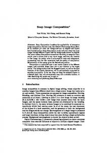
Figure 1. Generating radially polarized self-accelerating vector beams. (a) A radially polarized He-Ne laser beam is diffracted from a binary modulated cubic phase mask. Then, it is optically Fourier transformed and recorded at the focal plane and beyond. As illustrated, the radial polarization singularity (white line) and the highest intensity lobe (red line) propagate along different trajectories. (b,c) Comparison between the numerically calculated diffraction patterns of the known scalar Airy beam and the radially polarized Airy beam at the focal plane. As can be seen, the main intensity lobe is imprinted with radial polarization singularity. (d–h) Experimental and numerical results of radially polarized Airy vector beams after applying a polarizer. Polarization direction is denoted by the white arrow (un-polarized, 45° polarized, x polarized, y polarized, respectively).
pattern of the RAVB tail at the focal plane is also formed by the radial polarization as every two adjacent lobes interfere destructively with anti-phase relations. Furthermore, as the beam propagates, it will be shown that the usual form of accelerating Airy beams can be observed, with a linearly polarized main lobe appearing and accelerating in space, while the polarization singularity is broadened and drifted into the beam’s tail.
Theoretical Background
Radially polarized light can be described as a solution of the wave-equation in cylindrical coordinate system20–23. Its transverse electric field component is given in the form. E(r, φ, z, t) = J1(αr)rˆe i(ωt −kz) (1) Where J1(x) is the first order radial Bessel function, r and rˆ are the radial coordinate and the radial unit vector respectively, and k is the propagation wavenumber in the propagation (z) direction. The radially polarized beam has a distinct signature in its Stokes parameters, namely the four-lobed structure of S1 and S2 parameters as depicted in Fig. 2 (top row). This unique signature will be used further in this report to establish the polarization properties of radially polarized Airy beams. The diffraction of a radially polarized beam by a grating will result in the creation of multiple diffraction orders, each of them still holds radial polarization distribution, as demonstrated previously29. An Airy beam is created by diffracting light through a binary cubic phase-grating with transmission function of the following shape: T (x , y ) = sign {cos(αx + β1x 3 + β 2y 3)}33,34. This transmission function creates the diffraction pattern presented in Fig. 1c, which is noticeably different from the linearly polarized Airy pattern presented in Fig. 1b, by the splitting of the main lobe, and the “checkerboard” pattern of the beam’s tail. These differences are direct outcomes of the polarization structure, and not of the intensity distribution alone. Under the paraxial approximation, this diffraction pattern may be analyzed by the convolution theorem35. F(z){E(x, y)T(x, y)} = F(z){E(x, y)} ⊗ F(z){T(x, y)} (2) Where F(z) representsthe optical propagation by Fourier transform to plane z = f, where f is the focal length of the lens, E(x, y) is the incident radially polarized beam and T(x, y) is the transmission function of the diffractive element generating the Airy beam. It is understood that F(z){E(x, y)} represents the diffraction of the radially polarized Scientific Reports | 6:34272 | DOI: 10.1038/srep34272
2
www.nature.com/scientificreports/
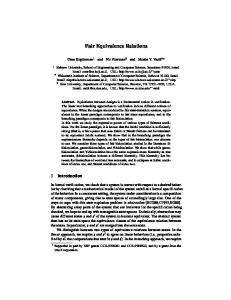
Figure 2. (Top row) Stokes parameters of radially polarized light. The distinct polarization structure is manifested by the four-lobe form of parameters S1 and S2. S3 which should be zero is indeed noticeably weaker yet it is not identically zero due to inaccuracies in polarizers and QWPs used. (Middle row) CCD image and S1 and S2 parameters for RAVB’s at the focal plane. Note the clear sign of radial polarization. (Bottom row) S0–S2 parameters for the RAVB after propagating 10 cm beyond the focal plane. As can be observed, the radial polarization singularity is drifted towards the beam’s tail.
beam and F(z){T(x, y)} = Ai(x, y, z) is the Airy function. While the diffraction of most beams is characterized by broadening, the Airy beam will preserve its shape, and shift laterally1. The convolution in Eq. 2 means that the propagation of the combined RAVB is the propagation of the two functions (Radially polarized incident beam, and Airy pattern), superimposed. Therefore, the Airy’s curved trajectory will result in a shift of the Airy pattern with respect to the origin of the radial polarization distribution as shown in Fig. 1(a). Similar separation has been observed with Airy-Vortex beams where the phase singularity is separated from the Airy’s main lobe31,36. In this paper we observed and measured for the first time, this separation dynamics for the polarization singularity and highest intensity lobe. It must be mentioned that the singularity in Vortex-Airy beams is originated from a singular phase distribution, while in our case, it evolves directly from the polarization structure, which will yield different propagation characteristics in non-isotropic media.
Experiments Description
Our experimental setup is fairly simple (see Fig. 1a): a He-Ne laser beam (λ ≅ 633 nm) is passed through a radial polarization converter (Altechna) followed by a binary phase grating and a lens. The binary phase grating is fabricated on a double-polished glass substrate by standard photolithography techniques, with a transmission function defined by: x T(x, y) = sign cos π105 + P2 (P3x 3 + P4 y 3) P 1
(3)
We have fabricated several gratings with different values of the parameters P1 to P4 to create Airy beams with different characteristics. Parameter P1 inversely controls the diffraction angle in the horizontal direction, while the combination of P2 along with P3 or P4 controls the Airy acceleration in the horizontal or vertical directions, respectively. The values of parameters P1 to P4 were chosen to fulfill the following requirements: (a) easy fabrication by standard photolithography procedures, which dictates that feature size is kept above 2 μm, and is also beneficial as Airy beams of high spatial frequency tend to smear over short propagation distances; (b) clear detection of all Airy lobes by our camera (i.e. separation between Airy lobes at the focal plane must be significantly larger than pixel size); and (c) the full diffraction pattern must fit into the CCD area. Typical numbers for these Scientific Reports | 6:34272 | DOI: 10.1038/srep34272
3
www.nature.com/scientificreports/
Figure 3. Propagation analysis of radially polarized Airy beams. The Airy pattern is examined in various distances from the focal plane. The rightmost panel shows the experimentally measured intensity patterns at different propagation distances, while the middle and left panels analyze the propagation and verify the theoretical prediction of acceleration and diffraction.
parameters (considering the use of standard lenses with focal lengths of 5–20 cm) are 1