User Interface Development Lifecycle for Business-Driven Enterprise Applications Kˆenia Sousa, Hildeberto Mendonc¸a and Jean Vanderdonckt
Abstract This work presents how business process models are described in terms of task models in order to solve traceability issues for large systems. The proposed approach presents a method with activities specifically selected for the scenario of developing UIs for enterprise applications founded on extensive business processes. Furthermore, some of these activities are detailed in order to make the work on UIs aligned with business processes and also useful for programmers. With the use of the tool proposed in this research, it is then possible to identify the UIs components that are impacted whenever changes are made on business processes.
1 Introduction The use of Information Technology (IT) has evolved over time from its traditional use as administrative support towards a more strategic role to enforce business processes (BP). In addition, there is a growing interest on the alignment of IT with organizational objectives from different perspectives, such as from business executives, IT managers, and academics. It is observed in the IT domain that most researches are focused on specifying the association between models from business and IT to support propagating changes ([1], [18]). Another observation is that many of these researches use software engiKˆenia Sousa Universit´e catholique de Louvain, Place des Doyens 1, Louvain-la-Neuve, Belgium, e-mail:
[email protected] Hildeberto Mendonc¸a Universit´e catholique de Louvain, Place des Doyens 1, Louvain-la-Neuve, Belgium, e-mail:
[email protected] Jean Vanderdonckt Universit´e catholique de Louvain, Place des Doyens 1, Louvain-la-Neuve, Belgium, e-mail:
[email protected]
1
2
Kˆenia Sousa, Hildeberto Mendonc¸a and Jean Vanderdonckt
neering models to address alignment issues. However, such strategies lack the consideration of a major aspect of information systems: their User Interfaces (UI). The impact of focusing on functional aspects is that many changes on business processes that affect UIs are not carefully treated, thus, leaving the decision of how changes impact UIs to be done in an ad-hoc manner. This effect is even more negative when we address large systems in which changes in business process rules are common and may have impact on even hundreds of UIs, thus, leading to the need to define strategies to maintain the traceability between business process and UIs whenever changes are requested. Certain changes on business processes that have a direct impact on UIs may be related to different reasons, therefore, can be classified in order to aid in organizing their impact on UIs: (1) components, new data that need to be informed may result in new elements on UIs; (2) navigation, updating organizational goals that influence responsibilities of professionals may result in new navigation between screens; (3) internal structure, change in the way of working and approaching users may result in new sequence of fields; (4) external structure, new activities that professionals must execute may result in new UIs; etc. Such details of ordering of components, of screens, positioning of components on screens, and navigation aspects are only expressed in UI models, not present, for instance in use case, class, and activity diagrams of UML. However, there are few works in the literature that study the alignment of business process and UI models, such as [13] and [14]. Aiming at supporting the development of UIs and their alignment with business processes, the overall research goal is to correlate business and UI by 1) defining the association of business process with UI models, and 2) presenting a prototype of a tool for model transformation that addresses both semi-automatic generation of UIs and traceability. This proposal is mainly aimed towards organizations that are driven by their business processes, and therefore, want their systems to address such processes in a way that as the processes are created, maintained, and evolved, so are its supporting systems.
2 Related Works There are recent works on the domain of model-driven architecture that discuss about traceability in model-driven development and its importance for analyzing alignment to requirements, impact and propagation of changes, etc. However, the most common use of traceability in model transformations is between data models and class diagrams, such as in [17], which discovers useful trace information from model relations. In the work of [9] on the traceability in model-driven development of business applications, they link artifacts from the development process that range from software requirements, test cases, design objects and code fragments. It does not mention any artifact for UI and the artifacts are not necessarily models, but sometimes text documents, for instance. On the other hand, it focuses
User Interface Development Lifecycle for Business-Driven Enterprise Applications
3
on how software development techniques aid in traceability, in their case, they use aspect-orientation. Moving towards valuing integration with UI, it has been agreed by academics and practitioners that the potential of IT in enterprise applications depends on how it is used, which is directly influenced by the UI [16]. Therefore, there is a growing interest on UI in the business domain, as it is possible to verify in some works done in IBM research centers, such as [14], in which the focus is on designing low-fidelity prototypes based on business process models. Another example is a recent work of Stolze et al. [12], in which they call attention that only relying on workflow models may be problematic to represent aspects of the user interaction because it is difficult to consider specific user requirements in such models. Aligned with the idea that information from business processes are not enough for UI design, the work of [8] advocates for a hybrid approach for modeling combining task models and process models. Similarly, [4] proposes a solution to use both workflow and task models to design role-centered UIs. It associates tasks in BPMN model with the highest level of task models. However, there is a limitation in this approach because even though the company in their case study decomposed their business process models in tasks; not all business process models have only one level of decomposition. It is possible to have processes composed of at least three different levels: sub-processes, activities, and tasks. When modeling task models, they adopt a hierarchical sequence-oriented style, but fixed sequence is not as broad as the variety of possibilities provided by different operators that enable a richer user interaction. Besides these two divergences, this approach is similar to ours since it adopts a process that starts with business processes (in their case, more specifically a workflow model, responsible to manage business processes) and finishes in the Final UI (FUI) using several models, including task model, dialogue model, similar to Abstract UI (AUI), domain model, and Concrete UI (CUI). Differently from our approach, [15] uses data group concepts to link design elements to business process models. A data group is a subset of data elements that appear together on a UI. In our case, we use task models as the link between business process and UIs, without neglecting data elements, which are related with tasks. Since tasks are related to UIs, there is, thus, an implicit relationship between data elements and UIs. Therefore, besides associating business with data, we also add the concern on behavior, provided by task models.
3 Business Process and User Interface Model Alignment With a detailed analysis of the specification on Business Process Modeling Notation, it was detected that some business process elements can be transformed into elements in a task model. For more details on the descrption of business process elements, reference the specification [7]. The relationships between tasks in a task model are different from the ones used in business processes; therefore, there is a need to correlate them. Table 1 specifies
4
Kˆenia Sousa, Hildeberto Mendonc¸a and Jean Vanderdonckt
the association of the relationships in business processes and in task models, with the rationale behind the decisions explained as follows. (1) Sequence Flow and Enabling operator represent the order in which activities are performed. (2) In cases when an activity passes information for the execution of the next activity, a Data Object can be associated to a Sequence Flow. (3) Considering two activities A1 and A2, the use of a Rule Intermediate Event before A2 can trigger a named rule that momentarily pauses the execution of A1 while A2 is executed, and a Link Intermediate Event after A2 is finished connects to an intermediate event in A1, going to the moment where A1 was paused. The use of these triggers is in accordance with the Suspend/Resume operator that affects the flow of activities by momentarily interrupting one activity as another one is executed. (4) Both the exclusive decision and the deterministic choice represent a point in the process where the first alternative that is chosen determines the flow that will be taken. (5) Many combinations of the alternatives can be selected with Inclusive decision, but it is also necessary to use the Exclusive merge in order to express that only one of the activities is expected to be fully accomplished and its result to be passed through the flow, as a manner to be aligned with non-deterministic choice. (6) When two activities are competing, and one is being performed, it may be interrupted by the second one, but the interrupted one is canceled by triggering the cancel event as soon as the second one starts, similar to disabling. (7) Ad-Hoc marker in a sub-process composed of activities that can be performed in any order using the attributes of an embedded sub-process addresses the same function as an independence operator. (8) In cases when two or more activities may be executed in parallel, the parallel gateway and concurrency serve the same purpose. (9) When activities are performed in parallel, similar to the previous situation, but they also synchronize data, data objects and information passing are added to the flow. Table 1 Association of business and task elements No.
Business Process
Task Model
1 2 3 4 5 6 7 8 9
Sequence Flow Sequence Flow + Data Object Rule Intermediate Event + Link Intermediate Event Exclusive decision Inclusive decision + Exclusive merge Cancel Intermediate Event Ad-Hoc marker in sub-process Parallel gateway Parallel gateway + Data Object
Enabling Enabling + Information Passing Suspend/resume Deterministic choice Non-Deterministic choice Disabling Independence Concurrency Concurrency + info passing
Table 2 associates activity attributes from business processes with task properties from task models. (1) The conditional flow can have expressions that determine whether or not the task in this flow will be used, which can express that a task is optional, depending of a certain condition. (2) Standard Loop determines that an activity is performed repeated times, similarly to the Iteration. (3) Multi-instance
User Interface Development Lifecycle for Business-Driven Enterprise Applications
5
loop has a numeric expression (its attribute MI Condition) that is evaluated once before the activity is performed and the result of this evaluation specifies the number of times that the activity will be repeated. This is in alignment with Finite Iteration, which expresses that a task can be iterated n times. Table 2 Association of activity attributes and task properties No.
Activity Attribute
Task Property
1 2 3
Conditional Flow Standard Loop Multi-Instance Loop + MI Condition
Optional Iteration Finite Iteration
Table 3 associates types of process activities and of tasks. Task types provide detailed information that helps in designing UIs. In business processes, tasks are the most atomic activities and in accordance to task models, they also have types. (1) User and Interaction types represent tasks performed by a human with the assistance of a system. (2) Service and application represent an automated task performed by the system. (3) Manual and Single User are related to tasks that are performed by a human without any aid from a system. (4) Abstract is used to group tasks, it has no specific meaning, which can mean that the type None is suitable for this case. (5) User type can be also appropriate to represent multiple users when the attribute Performers is informed to specify if it is performed by a group or an organization. Table 3 Association of process activities and task types No.
Process Task Type
Task Type
1 2 3 4 5
User Service Manual None User + Attribute Performers
Interaction Application Single User Abstract Multiple Users
This association of the main elements of business process with task models brings a contribution for UI development of information systems that are based on business process. This proposed approach closes the gap in UID lifecycle, which most commonly started with task models, leaving aside business processes. It is primordial to make it clear that the transformation of business process models into task models represents a first version of task models that need refinement. Such refinement can be done by human factors experts and UI designers, who update tasks and their relationships when new aspects may need to be created to address the richness and particularities of user interaction. The task model refinement can certainly be done with the participation of business analysts in order to allow consistency and alignment of task models with the business processes.
6
Kˆenia Sousa, Hildeberto Mendonc¸a and Jean Vanderdonckt
4 Case Study Our experience [11] comes from analyzing an organization decomposed in bank and insurance sub-divisions. The bank has a business department composed of a large group composed of around fifty business analysts, who are devoted to working on analyzing and evolving the business processes that drive the functioning of the bank and insurance. The insurance sub-division designs and develops systems that support the business processes. In their methodology, they specify business processes with flows of sub-processes and activities until reaching an atomic level in which tasks are associated to business rules and data. However, some organizations do not detail their business processes to such a level, instead, they maintain business process models in a high level description and detail them when necessary for system development using software engineering artifacts (e.g. use cases), as proposed in [3]. Since we can come across organizations that follow these divergent methodologies, it is aimed that our approach addresses both realities. Therefore, our proposal is also applicable in the prior example of high level business process description. In such cases, task models are also created from business processes, the main difference is that the refinement is more fine-tuned. This scenario is not addressed in this research work, which focuses on the context of the studied organization that has a great set of business process models that are specified into details. We conducted interviews with three business analysts, two system analysts and developers and two UI designers. During the meetings, we worked with examples of business processes and screens for insurance contracts. The main issues we detected and addressed in this organization were related to lack of correlation between business process and UI design; difficulties in doing impact analysis after changes; and difficulties to understand, to find, and to keep updated information spread in many different artifacts. In general, their business process models are composed of 60 elements that are handled for each process, which includes sub-processes, activities, and tasks, not even mentioning their business rules, which would increase this number by nearly 100 more elements to be considered. In the next section, we, then, present how these issues are addressed through method specification and tool support.
5 Method and Tool Support Using the associations between models to transform one source model into a target model provides a traceability chain among the models. And this chain supports identifying the impact of model changes on the system UI. Therefore, a tool called Usi4Biz (User Interface for Business) is being developed to manage these models using XML, which enables communication with other tools, such as modeling business processes in commercial tools that provide XML schemas that can be exported.
User Interface Development Lifecycle for Business-Driven Enterprise Applications
7
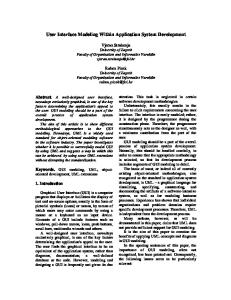
Once the models are imported into Usi4Biz (or even created within it), it is time for associating the models. Using the strategy proposed here to transform business process models into task models; their association is automatically created as the transformation is executed. This argument also applies for AUIs created from task models and domain models, and for CUI created from AUIs, since our proposal is founded on the Cameleon Reference Framework [2], which is composed of four development steps: create conceptual models (e.g. task model, data model, user model), create AUI, create CUI, and create FUI and supported by UsiXML [5]. However, there is also the scenario in which transformations between models are not performed; rather models are created, thus, making it necessary to make manual mappings between them. Therefore, in the organizational context under study, we propose the following method as depicted in Figure 1 by applying the method engineering strategy presented in [10], which considers their needs and goals, thus, making it more suitable for their reality and more feasible to be applied in the industry: 1) Business analysts design business process models in a business modeling tool; 2) Business analysts export the XML from the BP tool and import it into Usi4Biz; 3) System analysts create the domain model (Goal: Design UIs focused on the application domain); 4) Business analysts request to generate task model based on the BP XML; 5) UI designers and human factors experts refine the generated task models by updating tasks and relationships (Goal: Design UIs considering users mental models to perform their tasks); 6) UI designers list screen components based on task models (screen group, screen, screen fragment, and screen element); 7) UI designers create CUI models from task models; (Goal: Design focused on the look-and-feel of the system); 8) Programmers develop FUIs from CUI models. The complete description of this method, i.e., model-to-code compilation, is out of the scope of this paper and has already been addressed in several related papers, for instance, TERESA [6], supporting automated generation of UIs. Also, subject to further explanation in a future work is considering that CUI models in UsiXML have many details about the presentation, but not for design creativity in a web environment, for instance. To provide this, we consider the use of templates, with which the CUI is merged to produce a version closer to user’s needs. To manage templates, we consider the Apache Velocity [19], an open source template engine widely applied in web projects, without being restricted for them. However, the contribution here is that the task model is obtained from the business process model and that the UI resulting from task models are rigorously structured in terms of UI components and the support for traceability. Usi4Biz supports identifying the impact of changes; whenever the business processes are updated, this tool can provide information of which other models are impacted, which is a parallel research work that is focused on traceability. However, in this paper we want to emphasize on the support for UI design, by demonstrating how the hierarchical structure of task models can aid in organizing UIs and its components, which are numbered in Figure 2: (1) screen group, a group of closely related screens; (2) screen, a state of the user interface when executing a task or
8
Kˆenia Sousa, Hildeberto Mendonc¸a and Jean Vanderdonckt
Fig. 1 Outline of the method with roles, artifacts and tools
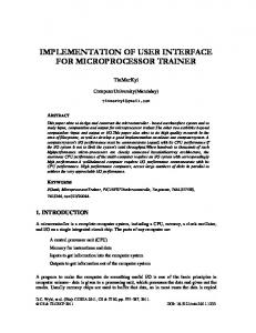
part of a task; (3) screen fragment, a container of related elements; and (4) screen element, the most atomic component. Figure 2 depicts the prototype of Usi4Biz, through which we aim at demonstrating the structure of the tool, not the contents of the models. On the left of the tool there is the business process extracted from the business process XML of a commercial tool, shown in a tree structure. On the middle, there is the task model generated from this business process. On the right, there are the UI components, which are applicable to generate both AUI and CUI models since the main difference between them is that CUIs are more detailed than AUIs with style guide specifications. This tool is being implemented in Java 6 using JAXP and JAXB libraries to process XML code. The definition of organizational standards for UI organization is of primordial interest for this organization, therefore, the use of the hierarchical structure of task models can enrich their UI standards by considering both structure and user interaction. One example that well illustrates the effective use of task models as a bridge between business process and UI design is the following: a joint work between different departments has reached the resolution of defining that a screen is composed of screen title, screen fragments, and an action button. Considering that they directly associate screens to sub-processes, this leaves no flexibility for UI designers. The result is that they have screens that resemble long forms, with a long scroll bar. In cases like that, the task model can be analyzed by UI designers to help group tasks that are most similar and group them in separate screens. Providing an overview of the complexity of their business processes, it is possible to understand the impact of fixing the association of screens to sub-processes. One
User Interface Development Lifecycle for Business-Driven Enterprise Applications
9
Fig. 2 Prototype of the tool Usi4Biz showing business process, task model and UI components
of the sub-processes under analysis in this case study contains 17 activities, in which each activity is composed of a varied number of tasks, ranging from 5 to 30 tasks, and each task runs business rules that also vary in quantity from only 1 to as much as 99.
Fig. 3 UI design decision to organize screens depending on complexity of activities
Figure 3 depicts the situation in which the UI designer analyzes the complexity of the tasks and decides to organize them in two screens, which are inter-linked. For space reasons, this figure depicts a decision towards grouping tasks on screens, not the contents of the tasks. The process of making the decision of how to group tasks in screens is very complex and requires experts to consider various aspects, such as correlation between tasks, correlation of data manipulated by different tasks, smooth navigation from a certain domain to another, among others. Figure 4 depicts a CUI designed for the task model according to organizational standards. To illustrate a problematic situation, knowing that tasks run business rules, consider that as users fill out fields, certain rules are executed in parallel. One possibility is that the return of a rule requiring to change values may appear on the side of a specific field that
10
Kˆenia Sousa, Hildeberto Mendonc¸a and Jean Vanderdonckt
Fig. 4 UI designed for one sub-process
is positioned outside the user sight since the scroll is down on the screen and the return is on the top of the screen. When users finish filling out the fields and press the confirm button on the bottom of the page, they receive a second warning, which could be avoided if the screen was not so long, which imposes restrictive range of vision and extra navigation (scrolling). On the other hand, Figure 5 reproduces the CUI for the second screen of the task model, which is much more compact and enables a better user experience. This strategy has been analyzed by top managers from the business department, who have given positive feedback considering cost analysis, feasibility of tool support and acceptance of change for the examples in which it was applied. The next steps are to select a pilot project and test the tool in future case studies.
User Interface Development Lifecycle for Business-Driven Enterprise Applications
11
Fig. 5 UI designed for a sub-set of activities in the sub-process
6 Conclusion This work presented a model-driven UI development lifecycle aimed for enterprise applications in organizations with extensive business processes. The experience in a large bank/insurance company enabled us to propose a solution for aligning business processes and UIs of their supporting systems, a major issue in this company as well as in many others in the competitive business word. This reality encourages us to validate this approach in other organizations with different business profiles aiming at analyzing their interest on the strategy and their openness to change. The proposed solution is composed of a method supported by Usi4Biz, a tool that maps models starting with the business process model, going to the task models until reaching UI components. Such mapping is possible through semi-automatic transformation or manual mappings, thus, letting designers free to decide whether the context is more appropriate for transformations or not. For future work, we intend to provide the transformations from business process model into task models through web services in order to enable interoperability by allowing many tools to access them. Acknowledgements Our special thanks to the company for allowing us to share information of our joint project. We gratefully acknowledge the support of the Program Alban, the Euro-
12
Kˆenia Sousa, Hildeberto Mendonc¸a and Jean Vanderdonckt
pean Union Program of High Level Scholarships for Latin America, under scholarship number E06D103843BR.
References 1. Aversano, L. Bodhuin, T., and Tortorella, M. Assessment and impact analysis for aligning business processes and software systems. In Proc. of SAC2005, pp. 1338-1343. 2. Calvary, G., Coutaz, J., Thevenin, D., Limbourg, Q., Bouillon, L., and Vanderdonckt, J. A Unifying Reference Framework for Multi-Target User Interfaces. Interacting with Computers 15, 3, June 2003, pp. 289-308. 3. Jones, S. Enterprise SOA Adoption Strategies. C4Media Inc. Publisher, 2006. 4. Kristiansen, R., Trtteberg, H. Model-Based User Interface Design in the Context of Workflow Models. TAMODIA 2007, Springer-Verlag, Berlin, 2007, pp. 227-239. 5. Limbourg, Q., Vanderdonckt, J.: UsiXML: A User Interface Description Language SupPorting Multiple Levels of Independence. In: Matera, M., Comai, S. (eds.): Engineering Advanced Web Applications. Rinton Press, Paramus, 2004, pp. 325-338. 6. Mori G., Patern F., Santoro C. Design and Development of Multidevice User Interfaces through Multiple LogicalDescriptions. IEEE Transactions on Software Engineering, August 2004, pp. 507-520. 7. OMG, Business Process Modeling Notation Specification, 1.0, February, 2006. 8. Pontico, F., Farenc, C., Winckler, M. Model-Based support for specifying eService eGovernment Applications. TAMODIA 2006, EDM-Luc, Hasselt, 2006, pp. 43-50. 9. Rummler, A., Grammel, B., Pohl, C. Improving Traceability in Model-Driven Development of Business Applications. ECMDA Traceability Workshop (Haifa, Israel), 2007. 10. Sousa, K., Mendonca, H., Vanderdonckt, J., Towards Method Engineering of Model-Driven User Interface Development. Proc. of TAMODIA2007, Springer-Verlag, Berlin, 2007, pp. 112-125. 11. Sousa, K., Mendona, H., Vanderdonckt, J., Rogier, E., Vandermeulen, J. User Interface Derivation from Business Processes: A Model-Driven Approach for Organizational Engineering. Proc. of 23rd ACM SAC2008, ACM Press, New York, 2008, pp. 553-560. 12. Stolze, M., Riand, P., Wallace, M., Heath, T. Agile Development of Workflow Applications with Interpreted Task Models. TAMODIA 2007, Springer-Verlag, Berlin, 2007, pp. 2-14. 13. Sukaviriya, N., Kumaran, S., Nandi, P., and Heath, T. Integrate Model-driven UI with Business Transformations: Shifting Focus of Model-driven UI. In: Proc. of MDDAUI05 (Montego Bay, Jamaica), CEUR Workshop Series, Vol. 159, 2005. 14. Sukaviriya, N., Sinha, V., Ramachandra, T., Mani, S., and Stolze, M. User-centered Design & Business Process Modeling: Cross Road in Rapid Prototyping Tools. In Proc. of Interact07, Springer-Verlag, Berlin, 2007, pp. 165-178. 15. Sukaviriya, N., Sinha, V., Ramachandra, T., Mani, S. Model-Driven Approach for Managing Human Interface Design Life Cycle. MoDELS 2007, pp. 226-240. 16. Sujitparapitaya, S., Janz, B. D., Wetherbe, J. C., Sammet, D. Ascension Health Systems: Enterprise user Interface Approach to Organizational Data Management. In 34th Hawaii International Conference on System Science, 2001. 17. Vanhooff, B., Van Baelen, S., Joosen, W., Berbers, Y. Traceability as Input for Model Transformations. ECMDA Traceability Workshop (Haifa, Israel), 2007. 18. Vasconcelos, A., Caetano, A., Neves, J., Sinogas, P., Mendes, R., and Tribolet, J. A Framework for Modeling Strategy, Business Processes and Information Systems. In Proc. of IEEE EDOC, IEEE Computer Society Press, Los Alamitos, 200. 19. The Apache Velocity Project. (Available via Apache, 2008), http://velocity.apache.org. Cited 01 Jan 2008.