Using Army Force-on-Force Simulations to Stimulate C4I Systems for Testing and Experimentation Michael R. Hieb, Ph.D. Modeling and Simulation Division AB Technologies, Inc. 1901 N. Beauregard St. Alexandria, VA 22311-1705 (703) 575-2800
[email protected] Lieutenant Colonel Donald H. Timian Army Model and Simulation Office 1111 Jefferson Davis Highway Crystal Gateway North, Suite 503E Alexandria, VA 22202 (703) 601-0012 ext 32
[email protected]
Abstract Simulation interfaces to Command, Control, Communications, Computers, and Intelligence (C4I) systems are essential for testing and experimentation. It is impractical to carry out large-scale tests in the field due to constrained resources and reduced availability of support units and equipment. Model and Simulation (M&S) systems have standardized on certain protocols and architectures for interoperability, such as the High Level Architecture (HLA). The C4I community is also moving to standardize on the Joint Technical Architecture (JTA) and the Defense Information Infrastructure Common Operating Environment (DII COE). These interoperability efforts can facilitate interfacing to C4I systems, if interface standards that align these two domains are developed. It is currently extremely difficult to interface Army C4I systems to standard Army simulations due to fundamental differences in their architectures and systems. The interfaces that have been constructed are limited in reusability. Historically this is due to the lack of common data models in the Army C4I systems, making each interface unique. A major objective of the Army Model and Simulation Office (AMSO) is to develop the technical infrastructure, architecture, and standards to allow simulations to interoperate with live C4I systems. In this paper, we outline a new approach that focuses on common data and software components as opposed to building “black box” interfaces.
Form Approved OMB No. 0704-0188
Report Documentation Page
Public reporting burden for the collection of information is estimated to average 1 hour per response, including the time for reviewing instructions, searching existing data sources, gathering and maintaining the data needed, and completing and reviewing the collection of information. Send comments regarding this burden estimate or any other aspect of this collection of information, including suggestions for reducing this burden, to Washington Headquarters Services, Directorate for Information Operations and Reports, 1215 Jefferson Davis Highway, Suite 1204, Arlington VA 22202-4302. Respondents should be aware that notwithstanding any other provision of law, no person shall be subject to a penalty for failing to comply with a collection of information if it does not display a currently valid OMB control number.
1. REPORT DATE
3. DATES COVERED 2. REPORT TYPE
1999
00-00-1999 to 00-00-1999
4. TITLE AND SUBTITLE
5a. CONTRACT NUMBER
Using Army Force-on-Force Simulations to Stimulate C4I Systems for Testing and Experimentation
5b. GRANT NUMBER 5c. PROGRAM ELEMENT NUMBER
6. AUTHOR(S)
5d. PROJECT NUMBER 5e. TASK NUMBER 5f. WORK UNIT NUMBER
7. PERFORMING ORGANIZATION NAME(S) AND ADDRESS(ES)
AB Technologies Inc,Modeling and Simulation Division,1901 N. Beauregard St,Alexandria,VA,22311-1705 9. SPONSORING/MONITORING AGENCY NAME(S) AND ADDRESS(ES)
8. PERFORMING ORGANIZATION REPORT NUMBER
10. SPONSOR/MONITOR’S ACRONYM(S) 11. SPONSOR/MONITOR’S REPORT NUMBER(S)
12. DISTRIBUTION/AVAILABILITY STATEMENT
Approved for public release; distribution unlimited 13. SUPPLEMENTARY NOTES
The original document contains color images. 14. ABSTRACT 15. SUBJECT TERMS 16. SECURITY CLASSIFICATION OF:
17. LIMITATION OF ABSTRACT
a. REPORT
b. ABSTRACT
c. THIS PAGE
unclassified
unclassified
unclassified
18. NUMBER OF PAGES
19a. NAME OF RESPONSIBLE PERSON
27
Standard Form 298 (Rev. 8-98) Prescribed by ANSI Std Z39-18
1. Introduction There are several revolutions underway today within the Department of Defense (DoD). The Revolution in Military Affairs challenges us to be prepared for uncertainty; to be prepared to fight differently; and in different conflicts than we have fought before. Our focus has shifted to such things as information dominance, rapid force projection, and smart self-contained weapons. As we modernize our armed forces, this revolution is defining what we must buy. Likewise, the Revolution in Business Affairs directs that we place management emphasis on core competencies. There is an emphasis to reduce overhead, leverage computer technology, and implement integrated products. This revolution is impacting how we buy. For those involved in the acquisition of these new systems the use of M&S early and throughout the acquisition process – Simulation Based Acquisition - will become essential [Sanders, 1997]. M&S and C4I interoperability standards are needed to provide an infrastructure for Simulation Based Acquisition [Loper, 1999; McGlynn. and Timian, 1998a]. Within the Army, C4I systems are being tested more effectively and efficiently by using force-onforce simulations. These simulations stimulate the C4I systems under test via message generation and database exchanges. Simulations are also being used to load the C4I systems – and the associated communications network – with realistic traffic versus the more costly technique of using live forces. The Army is also using simulations to stimulate C4I systems in order to train its brigade, division, and corps staffs. Lastly, the Army is using simulations to stimulate live C4I systems in its Advanced Warfighting Experiments in an effort to analyze possible battalion through corps organizational structures; determine future battle command and information operations requirements; and develop division and corps Interface operational and logistical concepts. Standards While Army C4I interfaces to M&S have DII COE Data many benefits, their cost is high. There are Components Models many technical challenges as described in the next subsection. The goal of this paper is to Figure 1. Increased Scope of AMSO C4I/M&S Standards delineate an approach that will reduce the cost and complexity of interfaces and also increase functionality. At the heart of our approach is the premise that we can only make long-term progress by addressing issues within Simulations and C4I Systems (and Architectures) directly, rather than at an external interface. A derivative of this premise is that more effort should be placed on building in interface features in next-generation simulations and C4I systems. We show how this can be done in Sections 4 and 5. Another derivative of this premise is that we do not want to build a better interface. Instead, we see the need to migrate the functionality of the interface to the end systems, by providing Application Programmer Interfaces (APIs), common data models, common terrain, common software components (such as the DII COE and the HLA Run Time Infrastructure (RTI)), and common exercise methodologies. This broader scope of interface standards is shown in Figure 1, which not only involves standards for interfaces, but also common software components, as well as an element that is not often considered, data models.
Constructing reusable software interfaces, such as the Defense Model and Simulation Office’s (DMSO’s) Modular Reconfigurable C4I Interface (MRCI) [Hieb et. al., 1997; Lighter et. al., 1998], have not proven to be viable in the absence of standards and the current lack of alignment between C4I and M&S. Army Experiment IV (AE4) assessed the ability of current simulations and simulation-to-C4I system interfaces to support training in the application of situation awareness [Brennan, 1998]. None of the simulations examined in AE4 were capable of generating the data required to fully stimulate all of the Army Battle Command System (ABCS) C4I systems. The recommendation of AE4 was that C4I Systems and Simulations must be considered as a “single system” when designing interfaces. Thus, instead of identifying requirements for an external interface, our approach specifies the development of an infrastructure where developers can use standard data interchange formats, standard software components and standard data models to construct a specific interface for an event. We envision that interfaces constructed to this approach would be much “thinner,” in that most of what is in present interfaces would be built into the simulations or C4I systems. At the same time interface developers would be free from having to write custom software for message parsing and translation, and can concentrate on work related to the event. 1.1 The Problem The development of C4I interfaces to M&S is still a research area. A better understanding of interface requirements is necessary to build interfaces that will meet the Army’s training, testing, advance concepts/experimentation needs for its next generation C4I systems. Substantial experience with Army interfaces has shown that it is costly, time-consuming, and complex to bring live equipment to exercises, as discussed in Section 2. In addition to the cost, interfaces often limit functionality of the training, testing or experimentation event. Most existing C4I interfaces to M&S have been developed as a separate component added on after initial M&S development and typically handle a small subset of the messages or data necessary for interoperability. M&S systems rarely handle free text messages or consider how a message is carried (communication effects). Significant human intervention is needed to achieve realism for the testing, training, and experimentation audience [Carr and Hieb, 1998]. In order to have a complete interface, the data to be exchanged must be represented in both systems (C4I and simulation). However, the current status is that C4I systems and simulations 1) do not contain the same data elements; 2) represent data differently; and 3) are often unaware of the other’s data requirements. The Joint Technical Architecture-Army (JTA-Army) mandates use of specific data models for certain classes of information systems (such as C4I systems). However, Army simulations do not contain these data models resulting in misalignment of data across the interface. Each data element that does not have an exact match on the simulation side causes a translation/transformation to occur, with resulting cost and complexity. Since an interface must align any differences, the interface can become quite complex. Apart from the difference in data representations, certain critical limitations of current interfaces are due to a lack of functionality in Army simulations. Not all simulated units respond to external command and control messages. Constructive simulations that represent large force concentrations by aggregated units may not adequately fill out the common operational picture, requiring entity situational awareness data [Paola and Ressler, 1999]. Most force-on-force simulations lack realistic
communications since they assume perfect communications between simulated entities [Silva et. al., 1997]. The AE4 found that most of the data reported to the C4I systems by the simulation/interface systems is ground truth (vs. perceived truth data), but C4I always deal with perceived truth data [Brennan, 1998]. For examples and an expanded discussion of current interfaces see [Brennan, 1998], [Carr and Hieb, 1998], and [Carr and Hilton, 1997]. The reason for the above limitations is not due to the simulation developers, but rather a divergence between C4I and M&S representations. To date, such interfaces have not been considered one of the primary design requirements for either system. In the absence of consistent C4I data models, simulations have developed their own representations of C4I processes, which are not aligned with C4I data models, such as the Joint Common Database (JCDB) used in the next generation of Army C4I systems, and the Army Battle Command Systems (ABCS) [Hieb and Blalock, 1999]. The fundamental problem is that C4I interfaces to M&S are hindered due to the lack of standards. M&S systems have standardized on certain protocols and architectures for interoperability, such as the HLA and previously, the Distributed Interactive Simulation (DIS) protocol. The C4I community is also moving to standardize on the JTA and the DII COE. These efforts need to be related to one another if interface standards that align these two domains are developed [Hieb and Staver, 1998]. [Hieb and Staver, 1998], [Timian et. al., 1999], and [Flournoy, 1998] discuss interoperability solutions based on interfaces between the standard architectures (e.g., HLA and DII COE), as opposed to more specific interface standards. Finally, it must be noted that C4I Interfaces can only go as far as the C4I systems themselves. Currently, the Army Tactical Command and Control Systems (ATCCS) and the Global Command and Control System (GCCS) use different data models. Thus, constructing a common interface to ATCCS and GCCS is not really possible, in that there will have to be several translations between the syntax and semantics of the two data models. 1.2 Definition of Terms Because of the different perspectives between the M&S and C4I communities, we will identify different uses of terminology to attempt to clarify the concepts in this paper. The term “C4I modeling” has different meanings to different communities. C4I modeling can involve either 1) modeling the communications burden of a network, or it can mean 2) modeling the actual messages and data that a C4I system sends and receives. Thus, the Network Warfare Simulation (NETWARS), a J-6 program, does C4I modeling (as in the first sense) in that it predicts the throughput of the communications architecture that supports a Joint Task Force. But it does not model the individual messages. The second definition of C4I modeling is primarily concerned with the content (semantics) of the messages, as opposed to the throughput of the networks. A typical force-on-force simulation used for C4I stimulation, such as Janus, must have a C4I interface to translate simulation objects to C4I data. In this case, C4I modeling is a combination of the live C4I system and a simulation, tied together with an interface. Communications are often ignored in this second type of C4I modeling, or represented as second order effects. The term “M&S” also has different meanings. In communications modeling, discrete event simulations such as the Optimized Network Engineering Tool (OPNET) simulation, which have
physics level models of propagation effects, are used. For C4I interfaces, force-on-force simulations are used that model the behavior of units, often faster than real time. Another area of difference concerns “data.” C4I systems have data models, but simulations have (for the most part) object models. The two types of models are used for the same purpose (abstract representation) but are seen as different due to the difference in implementation. Simulation developers have the perception that “data,” is primarily information that instantiates object instances such as mobility coefficients, or tables giving sensor range data. Ironically, in this paper, C4I modeling is not considered as constructing object models of C4I equipment and software in force-on-force simulations. This is considered as modeling information warfare, and is only now being developed as a concept at the DoD level. 1.3 Paper Organization The remainder of this paper is organized as follows: Section 2 describes why interfaces are needed to simulations for the development and testing of C4I systems; Section 3 proposes a C4I Interface to M&S Technical Reference Model; Section 4 describes the C4I and M&S Architectures mandated in the JTA-Army; Section 5 gives examples of using DII COE components to interface to Simulations; and Section 6 concludes with a discussion of the goals that the Army has for future C4I interfaces. 2. Interface Development Today The following sections give background on how simulation to C4I interfaces have been developed to date, and a brief description of the current process of testing Army C4I systems prior to fielding. While the later sections concentrate on the technical issues, it is important to keep in mind how interfaces are being used now, and their historical development. 2.1 SSMs – A Case Study In the early 90s the Army's Test and Experimentation Command (TEXCOM) was faced with a difficult - and at the time - unique problem. "How do you operationally test a corps worth - over 200 systems - of Army Tactical Command and Control Systems (ATCCS) without putting the corps (and the associated controllers, data collectors, and army sized opposing force) in the field?” By law operational testing requires that the system under test be tested in an environment as close to wartime conditions as possible. For Command and Control (C2) systems operational testing requires not only soldiers, who have been trained on the C2 systems to operate them, but also decision makers who 1) must make decisions using the information provided by the C2 systems and 2) use the same C2 systems (hooked to a tactical communications network) to distribute their decisions and monitor the results. In other words, a wrap-around-synthetic-environment – a simulation. The solution that TEXCOM hit upon was to immerse the corps – via a simulation (the Corps Battle Simulation (CBS)) – in a seven day, twenty-four hours a day fight where each of its ATCCS systems would be stimulated using a set of Simulation Support Modules (SSMs) that emulated the tactical data flow and message formats each ATCCS system received.
Not only did this solution cost less than one-tenth of a full-up, corps exercise (to include the cost to develop the SSMs), it also allowed the Army to look at ATCCS interoperability issues that, at that time, had only been marginally assessed. It also was discovered that the SSMs could be used to train a digital staff. In addition, the SSMs were so successful that they have been used in high level staff training exercises such as the Battle Command Training Program and the Command and General Staff College Prairie Warrior exercise [Loper, 1999]. However, this process of using the SSMs is expensive and time consuming, requiring live command posts and hundreds of man-hours to prepare unique data bases for each exercise. A fixed facility, with easily reconfigurable or mock command posts – along with the associated C4I interfaces and simulations – was required. 2.2 Today - Testing at the CTSF Originally created for the integration of the ATCCS system software process in support of the Army’s Force XXI, brigade level, Advanced Warfighting Experiment, the Central Technical Support Facility (CTSF) at Fort Hood, Texas are the perfect location for the integration – in support of both developmental and operational testing – of analytical and training simulations; C4I interfaces; and future Army C4I systems. Fort Hood is also the home of the Army’s First Digital Division (FDD) – the 4th Infantry Division (Mechanized) [Loper, 1999]. Today several constructive simulations (including the Warfighter Simulation 2000 (WARSIM) Integrated System Prototype (ISP), Modular Semi-Automated Forces (ModSAF), and Janus) are being used at the CTSF to provide realistic message and data loading of ABCS systems. As with the SSMs, the limiting factor in such testing is the interfaces used to inject data from the simulation into the live systems, and to present relevant stimuli back to the simulation systems. Better interfaces provide more functionality in data collection during experimentation to validate system architecture concepts and to verify that functional requirements are being met. 3. A C4I to M&S Technical Reference Model This section presents an Technical Reference Model (TRM) for a complete C4I to simulation training interface and also functional requirements for such an interface. This discussion will set the stage for the subsequent sections, and is intended to identify the information needed when interfacing systems from the M&S and C4I domains. 3.1 Identifying Information Exchange Requirements Prior to discussing specific standard software components and data models, it is desirable to identify and classify the information that must flow across an ideal interface. This will not be possible until there is a common understanding of what constitutes conceptual interfaces and the identification of one or more technical reference frameworks. Second, in order for M&S developers to build internal interface features that will work across a C4I domain (and C4I developers to build in M&S features) the different types of information need to be standardized to some extent. Data Interchange Formats (DIFs) such as the Command and Control Simulation Interchange Language (CCSIL) [MITRE, 1997] need to be created for specific information classes. We identify three broad classes that are necessary to meet conceptual requirements that would result in full interoperability:
q q q
Persistent Data Non-Persistent Data Execution Control
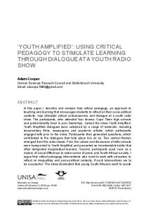
Persistent Data refers to the class of information that is stored during the operation of the simulation. Information belonging to this class is typically initialized prior to execution and changes less frequently than Non-Persistent Data during simulation operation. Non-Persistent Data refers to the class of information that is transient, corresponding to interactions between entities or objects in the simulation or C4I database, or updates to an entity’s state. A third class of information necessary for a complete interface is Execution Control. Simulations typically have a set of protocols that allow an operator to control their execution and synchronize their operation with other simulations, including time management functions. Current C4I systems do not have protocols that correspond to these, however future C4I systems must have such protocols to enable them to be fully interoperable with simulations. One example of this class is the requirement for After Action Review (AAR). While simulations can typically replay a scenario that had previously occurred, it is desirable to synchronize C4I systems with this playback to show the information available for decision making for particular events. Unless these requirements are specified to C4I developers, future C4I systems will not have the capability to perform such operations. Birkel [Birkel, 1998] has developed a Synthetic Natural Environment (SNE) Conceptual Reference Model that is very similar to the TRM described here. It is more focused on environmental effects but still is oriented towards interfacing to C4I systems. It provides an excellent comparison and alternate viewpoint to the TRM. The TRM is more focused on information exchange and the SNE Conceptual Reference Model is more focused on functionality. The SNE Conceptual Reference Model authoritatively extends the description of those classes in the TRM that deal with the environment (interfacing to physical and environmental models in the TRM). Others have proposed models of C4I/M&S interoperability, which were reviewed during the development of the TRM described here. Layman [Layman et. al., 1997] gives a model of an interface for multi-level team training. This model divides information into C2, Tactical Communications, Combat Systems, and Sensors classes. These classes all fall into the NonPersistent Data category in the proposed model. Farinacci, Roberts, and Winner [Farinacci et. al., 1996] describe an architecture for establishing interoperability between a C4I system and CGF Simulation using the HLA. McKenzie and Risner [McKenzie and Risner, 1998] describe how the Joint Simulation Systems (JSIMS) is approaching interfaces to C4I systems, detailing how the JSIMS Architecture supports External Systems. 3.2 The Technical Reference Model Figure 2 shows a notional Computer Generated Forces (CGF) simulation with the types of information which a complete interface must accommodate. The interface design is not specified. The function of the interface is to 1) control the information flow between the C4I system and the simulations and 2) to align the information among the systems so that the information is received in a
system’s native format. Note that all of the information may flow bi-directionally. Thus M&S systems would need to have the capability built to accept initialization data from C4I systems, as well as being able to pass scenario data to initialize C4I systems. The notional CGF can be thought of as an example of a current generation object-oriented simulation, having different modules for Exercise Control, Behaviors, Environment, and Physical Models tied together with a Run Time Framework. Persistent data is stored in a Scenario Database. Current simulations, such as ModSAF [Ceranowicz, 1994], can be easily mapped to this notional CGF. Each of the 11 separate information types is a candidate for a separate Reference Federation Object Model (FOM). Figure 2 depicts several other specific interface requirements:
Exercise Control Interactions Initialization/Execution
C 4 I I n t e r f a c e
Data Collection
Exercise Control Module
Non-Persistent Data Orders Reports Imagery Tracks Communications Effects
Persistent Data Unit Data (OB, TOE, Symbology, etc) Mission & Plan Information Comms Plan (Radio/Network Setup, etc) Weather Data Terrain Specification
Behavior Models Module Physical Models Module Communication CommunicationModel Model Environmental EnvironmentalModels ModelsModule Module
Run-time Framework
Scenario DB Figure 2. A C4I Interface to M&S Technical Reference Model
q
Exercise Control Interactions are a type of Execution Control that is passed to control the conduct of an event. The controls would allow, for example, “checkpointing” of both simulations and C4I systems, as well as allowing pausing of the C4I system at appropriate points in the exercise. Initialization and AAR protocols would also fall in this category. Exercise Control Interactions would be interfaced to an Exercise Control Module of a simulation. Logging is explicitly identified as a separate category due to the importance of this function.
q
Orders are a type of interaction that convey C2 information. Translation of this class of information has been extremely difficult to achieve with current interfaces [Carr and Hieb, 1998]. Presently, C4I systems do not support the generation and maintenance of this C2 information in a uniform manner.
q
Reports are a type of C2 information about the state of an entity. The majority of current interfaces deal with this class of situational awareness information. Typical report information includes location and status, and may be sent to the C4I system as either tactical messages or data updates. Both Orders and Reports would interface to Behavior Models of a simulation, affecting the decision making of simulated units. If the simulation offers a high degree of fidelity in C2, it may associate these interactions with Communication Effects.
q
Imagery is a type of unprocessed visual C2 information from a sensor. This data is characterized by high bandwidth requirements and the need to be processed or analyzed prior to use. Imagery would also interface to Behavior Models of a simulation, affecting the decision making of simulated units. Examples of this would be video from an Unmanned Aerial Vehicle (UAV) or a Moving Target Indicator (MTI) radar image from a Joint Surveillance and Attack Radar System (JSTARS) [Williams, 1998].
q
Track Data is information regarding the physical state of entities (or objects). This class of information also includes physical interactions between objects (such as weapon effects). A simulation may need to know the location of a live unit, even if it is not sending out report messages (Reports). Alternatively, air tracks of a simulated aircraft may need to be generated for a radar screen. If the data passed to the interface is ground truth, then the data should have effects applied to turn the data into perceived truth. These interactions would be processed by the Physical Models Module of a simulation.
q
Communication Effects (CE) emulate the characteristics of the communications channel by which the information in classes Orders and Reports are passed [Carr and Roberts, 1997; Silva et. al., 1997]. In most cases, a CE interaction would be paired with a C2 interaction. This interaction would be interfaced to a physical device model (such as a radio model) that transmits or receives the CE interaction, in the Physical Models of the simulation.
q
Persistent Data covers a wide variety of information. This usually includes Order-of-Battle (OB) information as well as specification of the terrain to be used. Typically this information is not exchanged in current interfaces, but rather is manually aligned. As an example, a C4I system will have an OB database, and a simulation will have a completely different representation of these units. The simulation should be able to be initialized from a C4I system, just as a C4I system should be able to be populated with exercise data from a simulation. Persistent Data would be initialized at runtime and kept current during execution. This class of information would interface to the simulation’s Scenario Database, as well as the Environmental Models Module for dynamic updates during execution. Persistent Data includes: Weather Data – essential for training exercises; Communications Laydown – needed for initializing communications networks so that communication effects can be modeled; Mission and Plan information – necessary for generation of orders; Unit Data – including the OB and associated information; and Terrain Standards. Interchange of terrain formats has been problematic within the simulation domain as well as within the C4I domain.
3.3 The Army’s M&S Standards Development Process The TRM is intended to serve as a framework for the development of standards. The Army has a standards process for M&S, managed by AMSO [McGlynn and Timian, 1998a] and [McGlynn and Timian, 1998b]. Of course, given our approach as stated in Section 1.1, we must also address and develop C4I Standards as well as M&S Standards. An example of influencing C4I standards is the development of the COE Message Processor (CMP) APIs, described in Section 5.2.1. Ideally there would be standards for each class of information in the TRM. For the Army M&S standards development, subject matter experts from various organizations throughout the Army are appointed to serve as Standards Category Coordinators (SCCs) by the Army Model and Simulation Executive Council. They serve as the proponents for developing M&S standards within their standards category. Team composition is interdisciplinary and represents organizations across the Army, as well as academia and industry. Each standard category team must work together to prioritize the list of Standards Development requirements. A complete description is given in the Army Model and Simulation Standards Report, FY99 [AMSO, 1999]. There are currently 19 standards categories. There is a specific category for C4I interfaces called C4I Integration. All the rest of the 18 categories relate, in some degree, to C4I Integration. Some categories such as Architecture, Command Decision Making, Communication Systems, Data, Dynamic Atmospheric Environments, Object Management, and Terrain directly impact C4I Integration. As an example, consider the Terrain Category. The Synthetic Environment Data Representation and Interchange Specification (SEDRIS) is a standard for Terrain [Stanzione and Chamberlain, 1998]. However, no C4I systems currently use the SEDRIS terrain standard for terrain interoperability. Future Army C4I systems have been directed to use the DII COE component, the Joint Mapping Tool Kit (JMTK). Army C4I Systems use many different terrain formats such as Digital Terrain Elevation Data (DTED) or Vector Product Format (VPF). All of these standards, SEDRIS, DTED and VPF must be considered prior to declaring a standard for interoperability between C4I systems and M&S. For a discussion of how the Army Unit Object Model Proposed Standard [Hodge and Bradley, 1998] aligns with Army C4I Data Models see [Hieb and Blalock, 1999]. 4. JTA-Army Architectures for C4I and M&S The JTA and JTA-Army mandate architectures for C4I and M&S. This section first discusses the JTA-Army and then the C4I standards that derive from it, and the M&S standards in Appendix G that derive from it. At the end of this section several viewpoints on how the C4I and M&S architectures should be aligned are presented, with a recommendation. [Hieb and Staver, 1998] treat this topic in more detail. 4.1 The Importance of the JTA The DoD JTA [JTA, 1999] and the JTA-Army [JTA-Army, 1998] have three mutually supporting objectives. The first is to provide the foundation for a seamless flow of information and interoperability among all tactical, strategic, and sustaining base systems that produce, use or exchange information electronically. The second objective is to provide guidelines and standards for
system development and acquisition that will dramatically reduce cost, development time, and fielding time for improved systems. The third objective is to influence the direction of the information industry’s technology development and research and development investment so that it can be more readily leveraged in Army systems. Studies of software reuse in Army and DoD systems indicate that the largest potential for reusing mission application software and process models is within an application domain [JTA-Army, 1998]. To better facilitate mission-application software reuse, four domains have been identified (the lead agency for the Army for each domain is shown in parenthesis): q q q q
Model and Simulation (AMSO); C3I (Program Executive Office (PEO) – Command Control and Communications Systems and Project Manager, Intelligence Fusion); Weapons (Weapon Systems Technical Architecture Working Group); and Sustainment (PEO – Standard Army Management Information Systems).
The domains of the JTA-Army are covered by appendixes to the main document that contain exceptions (replacing a core standard with a domain standard) or extensions (that add a domain standard to the main body set of standards). If a system relates to a domain, then both the core and domain standards apply to that system. The JTA-Army addresses both message-based and direct database-to-database exchange of data. However, future tactical systems within the scope of the JTA-Army (reference Section 4.2.2 -- Data Model) must be based upon the C2 Core Data Model (C2CDM). In addition, the Joint Variable Message Format (JVMF); US Message Text Format (USMTF), and the Tactical Digital Information Link (J Series) Message Formats are mandated in Section 4.2.4 -- Data Exchange, but only until mechanisms that use standard data elements are approved. 4.2 JTA C4I Standards 4.2.1 DII COE In JTA-Army Version 5.0 [JTA-Army, 1998] the Army adopted the DII COE concept and mandated the DII COE baseline specification and the DII COE integration and runtime specification. The DII COE is mission application independent, as well as: q q q q q
an architecture; an approach; a collection of reusable software; a software infrastructure; and a set of guidelines and standards.
Per the DII COE Architecture Oversight Charter [DII COE, 1997], portions of the DII COE are being updated using requirements generated by 20 Joint Service Technical Working Groups (TWGs). The Army is the lead for several TWGs that are critical to C4I interface developers, such as: the COE Message Processor (CMP), Communications Services, Data Access Services, and Alerts. There are also TWGs for the Common Operational Picture; Visualization and 3D; and
C4I Database Data Distribution/ Replication Components
Applications JCDB
Comms Server
System Unique Database
COE Message Processor
DII COE Component
DII COE Component
Figure 3. ACII Components
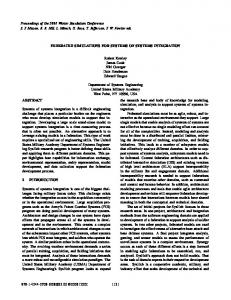
Mapping, Charting, Geodesy, and Imagery (JMTK). Many of these TWGs can be directly mapped to the Army’s M&S SCCs. 4.2.2 The Army Common Information Infrastructure In order to accomplish full interoperability with C4I systems, it is not sufficient for M&S developers to build in better messaging capabilities to their systems. As has been noted previously, C4I systems must also change. The main AE4 (evaluating simulation interfaces) recommendation was that the interface must be viewed as an end-to-end system comprising both the M&S system, the interface software and the C4I system [Brennan, 1998]. There are two areas where C4I systems will change in ways that make interoperability easier. First, C4I systems will increasingly utilize database updates as opposed to sending messages with a particular message protocol. Second, C4I system developers will increasingly use common data models that will utilize standard data elements. As an example of the future C4I system architecture, we describe an Army initiative to make the ABCS systems interoperable – the Army Common Interoperability Infrastructure (ACII). This concept, developed by the Horizontal Integration Technology Office of the Program Executive Office – Command, Control, and Communication Systems (PEO-C3S) is shown in Figure 3. It is based upon products compliant with the JTA and provides a flexible capability to achieve the Army, Joint, and combined interoperability required. It is based on an information management model rather than a message transaction model, while still providing support for current formatted messages for data distribution. The ability to use current and evolving message, data distribution, and data replication technologies permit the implementation to support interoperability across a wide spectrum of operations and interfacing systems. The ACII architecture is database centric with the database being the focus of all information operations. It is based upon DII products (the COE Message Processor [PEO C3S, 1998] and the
DII COE Communications Server) thus having a high degree of software reuse. The ACII will be in each of the ABCS systems in the future. 4.3 JTA Simulation Architectures Objective 1 of the DoD and Army Model and Simulation Master Plans states, "Provide a common technical framework for M&S" and includes, under sub-objective 1-1, the establishment of a common high level simulation architecture to facilitate interoperability of all types of simulations among themselves and with C4I systems, as well as facilitate the reuse of M&S components. To meet this objective the Under Secretary of Defense for Acquisition and Technology (USD A&T) designated the HLA as the standard technical architecture for all DoD simulations. The HLA is a technical architecture that applies to all classes of simulations including live, virtual and constructive. The live simulation class includes C4I interfaces, weapon systems/platforms with embedded collective training, and instrumented ranges. The virtual simulation class comprises human-in-theloop simulators. The constructive simulation class includes wargames and other automated simulation systems [JTA, 1999]. In Appendix G of the JTA-Army the HLA is mandated for all Army simulations. Thus, future Army C4I interface developers must develop interfaces that take into account the DII COE, the HLA, and the JTA-Army mandated message formats, data models, and data exchange standards. The additional standards areas proposed in this paper would better define the interface between the M&S domain and the other JTA-Army domains. 4.4 Relationship Between C4I and Simulation Domains Figure 4 shows an example of how most interfaces are currently implemented. Because the DIS standard does not align well with current tactical message formats, there must be a software translator to perform the interface functions. This translator is custom software, due to the complexities of unique C4I communications protocols/hardware and due to the variety of message formats. Projects have also interfaced C4I equipment to the HLA, such as MRCI [Hieb et. al., 1997; Lighter et. al., 1998]. These projects have emphasized the need to minimize translation and its overhead through use of common data elements [Thumim et. al., 1997].
Simulation
C4ISR System
DIS Data Format System Unique Comms
Custom Software
DIS Network
Message Format
Figure 4. Legacy C4I to M&S Interface Standards
The missing piece is a data interchange format that aligns both of the different standards architectures. A good example of this is SEDRIS [Stanzione and Chamberlain, 1998]. The SEDRIS is a DIF between the simulation terrain formats (such as S1000 or Standard Interchange Format (SIF)) and the C4I terrain formats (DTED, VPF). Neither the simulations nor the C4I use the SEDRIS format, but it allows conversion of data by providing a unifying representation. There is a large difference in viewpoint between the developers of simulations and C4I systems, especially in regards to the standards process. C4I developers feel strongly that simulations should use the data elements that real systems use. This leads to a standards framework as shown in Figure 5, with a DII COE segment in the simulation for direct database-to-database data element transfer. The JCDB is shown as an example of a C2CDM-derived data base. However, this interpretation is not familiar to simulations, and is not in accordance with the HLA. Figure 6 shows a standards framework that is simulation oriented. This assumes that the HLA will be hosted on C4I platforms, possibly as a DII COE segment. C4I developers are not familiar with the HLA and have traditionally not accepted this a valid requirement for their system. Figures 5 and 6 also show that making a DIF – or an API – a standard does not constrain the architecture. There will still be a need for a DIF even if one architecture predominates. Until each architecture uses the same data elements, there will be a need for translation. However, a good standard will minimize the translation necessary.
Simulation Data Interchange Format
C4ISR System
JCDB Data Model DII COE Comms Server
DII COE Comms Server
Figure 5. A C4I Developer’s View of C4I to M&S Interface Standards
Figure 7 proposes a framework for integrating JTA-Army simulation and C4I standards. The simulation standards architecture is the HLA and its standard for representation is the FOM. The C4I standards architecture uses the DII COE (although there may be other more specific standards involved). The standard for representation is either message formats (VMF, USMTF, etc.) or data models (using data exchange mechanisms). The HLA has a specific communications mechanism, the RTI, and the DII COE also has specific communication segments.
Simulation HLA RTI
HLA RTI
C4ISR System
Federation Object Model Data Interchange Format
Figure 6. A Simulation Developer’s View of C4I to M&S Interface Standards
Simulations C4ISR Systems
HLA RTI DII COE Comms
Federation Object Model
Message Format Data Model
Data Interchange Format
Figure 7. Relationship of C4I to M&S Interface Standards
5. Example of Using C4I Components in C4I to M&S Interfaces The ACII is a conceptual architecture and is currently being implemented using progressively improving versions of DII COE components and the JCDB. The difficulty in constructing interfaces to the ACII is not in what the end state is expected to be, but in how to accomplish the transition. The next three figures show a phased plan of how to prototype and construct M&S interfaces to the ACII. In these figures, the relationships and components are conceptual – no system architecture is implied. In order to make this example more concrete, we use specific examples of systems. The Maneuver Control System (MCS) Block IV is shown as the C4I system and the WARSIM ISP is shown as the Army simulation. However, any ABCS system and any Army simulation could be substituted, respectively. See [Timian et. al., 1999] for more details. 5.1 Concept of Using DII COE Components Figure 8 shows the first phase of interfacing to the ACII, by embedding the CMP in an M&S C4I interface. The CMP is designed to pass information in two directions. From the simulation to CMP, the translator provides the simulation data to the CMP for formatting to the appropriate tactical message format; in this case – given that the “target”, or stimulated, C4I system is MCS Block IV – a USMTF message. From the CMP to the simulation, the translator converts parsed USMTF messages into a simulation representation. The DII COE Comms Server is used to pass USMTF messages between the CMPs embedded in the interface and Block IV MCS.
Short Term
C4I System
Simulation System Comms Server
Comms Server
CMP
JCDB Translator
CMP WARSIM ISP
MCS
Figure 8. Using the CMP in the Interface
In Figure 9 the second phase of the M&S interface to the ACII is shown. Here both messages and data are being transferred. Note also that the translator is different. Instead of simply converting simulation data into USMTF messages or USMTF messages into simulation data, Figure 9’s translator is designed to take the information from the simulation, translate it, and “post” it – via an API – in the JCDB or retrieve the incoming information from the JCDB and pass it on to the translator. Depending on whether or not: q q
the stimulated C4I system is JCDB compliant and the information being passed between the simulation and the “target” C4I system is via the simulation center’s local area network (i.e., intra-TOC (Tactical Operations Center) vs inter-TOC),
C4I System
Medium Term
Data Replication
Data Replication Comms Server
JCDB
Simulation System
Comms Server
JCDB CMP
CMP MCS
Translator WARSIM ISP
Figure 9. Transition from Messages to Data
Long Term
C4I System
Comms Server
Simulation System Comms Server
Data Replication
JCDB
JCDB Data Replication
Translator WARSIM ISP
MCS
Figure 10. Data Replication in Interface
JCDB updates – whether originating at the C4I systems or the interface – are distributed to the other JCDBs and passed by the Comms Server. If the stimulated C4I system is not JCDB compliant or not part of the simulation center’s local network, then all relevant information between the interface’s JCDB and the C4I system is: q q q
first converted by one or the other CMP into an appropriate message format (i.e., USMTF, etc.); passed on by the Comms Server; and then provided by the appropriate CMP to its JCDB.
Figure 10 shows the third and last phase of constructing an M&S interface to the ACII, where the C4I systems have transitioned to primarily passing data. Thus the main information passed between the C4I and the simulation is via relevant data exchanges (assuming the intra-TOC limitation is no longer valid). However, even in the long term, there may still be a need for messages on a case-bycase basis. But the emphasis will be on data. Figure 11 depicts the potential to leverage the JCDB. Instead of needing a set of M&S C4I interfaces (perhaps as many as one for each “target” C4I system), only one interface – using standard C4I and DII COE components – is needed. 5.2 Using C4I Components in Army M&S Interfaces In order to achieve the vision depicted in Figure 11 not only must interfaces be built to accepted standards, but also simulation specific requirements must be incorporated into select DII COE components. Examples of this, for ACII components, include using appropriate APIs to the CMP and JCDB as described below.
Simulation System
C4I System AFATDS
ASAS Comms Server
Data Replication
JCDB MCS
Translator
AMDWS
TOC
CSSCS
WARSIM ISP
Figure 11. Potential to Leverage JCDB Interface
5.2.1 CMP The CMP is a multi-functional automated message processing system which contains state-of-the-art technology to process both inbound and outbound messages using a standard Graphical User Interface (GUI). Functional capabilities include: q q q q q q
internal routing; extraction of data from messages and their headers for forwarding to other applications or databases; standing request for information; automatic and interactive message generation; validation of inbound and outbound messages; and autofill of data from the database to a message or application.
As shown in Figure 12, an added benefit of using the CMP is that very soon it will be in a wide variety of systems that spread across the Services. The CMP module is logically bound by the communications module on one side and other supported processes and/or other COE modules on the other side. Processing of inbound messages from the communications front end includes essential functions such as field/format validation, profiling, standing request for information, parsing, and routing. The processing of messages for hand off to the communications module includes essential functions such as message and header preparation, validation, and coordination/release. The message processor is capable of processing any formatted or unformatted message which is validated by tables derived from the Joint Interoperability Engineering Office (JIEO) Central Data Base System (CDBS). The message processing module permits components to be employed independently, or in combination with other components, to perform a single, or group of, function(s). Figure 13 provides a top level functional flow of the message processing module and identifies the three major subordinate areas within the message
MCS CMP AMDWS CMP
AFATDS
ATCCS
ARMY FBCB2
CMP
CMP
GCCS CMP ASAS
CSSCS
CMP
CMP
MARINE TACTICAL SYSTEMS CMP
USAF CTAPS
JIEO
NAVY JIMCS
CMP
CMP MIL-STD-6040
Binary Files
MFDD
DII COE Comms Server
USMTF ARMY UNIQUE MARINE MTS OTH GOLD IEW COMCAT STANAG
Figure 12. CMP Usage Across the Services
processing module. The inbound and outbound processing components contain functionality specific to each of those processes. The third component is support services which contains functionality used by both the inbound and outbound processing components [PEO C3S, 1998].
Comms Server
D i s c r i m i n a t o r
Parsing/ Validation Journal Server Message Preparation CMP User Interface Figure 13. CMP Functional Flow Chart
S I M
A u t o f i l l
A P I s
Application or Database
In August 1998 the Simulation, Training, and Instrumentation Command’s (STRICOM’s) Project Manager (PM), WARSIM/C4I Simulation Systems (C4ISS) submitted simulation requirements for the CMP. This submission of requirements was preceded by a Technical Interchange Meeting between WARSIM and CMP to exchange requirements information. The requirements for simulations submitted included bi-directional messaging, multi-threaded messaging, auto message formatting without the CMP User Interface, multiple instances of CMP on single platform, and parsing to support C++ and Java data structures. Since then, these requirements have been incorporated in the CMP System Requirement Specification Version 2.0; and APIs were added to the Java version CMP. Team WARSIM has been actively involved in Beta testing and prototyping with this version of CMP since September 1998. The CMP is currently incorporated into the WARSIM development baseline for message processing and dependencies have been identified and placed upon CMP functionality. Team WARSIM expects to continue to work with CMP throughout its development. 5.2.2 JCDB The JCDB is an American National Standards Institute Standard Query Language (SQL) database management system and conforms to the DoD C2CDM standards. The JCDB focuses on data which is shared by two or more ABCS. Functional areas supported by the JCDB include, but are not limited to: Intelligence, Logistics, Communications, Network and System Management, Fire Support, Aviation, Air Defense, and Maneuver. The JCDB will be segmented throughout its iterative growth and each segment will be submitted for inclusion in the DII COE. The JCDB in its current configuration provides data to support the following Joint C2 functions: q q q q q q q q
display of friendly and enemy locations, activities, strength, status, estimated and current capability; display and tracking of resources and environmental factors to support Course of Action analysis; display and tracking of materiel locations, status, quantities, etc.; display and mapping of ground and air control measures; display and mapping of facilities; target nomination, engagement and damage assessment; evaluation and verification of reported information; and development of Operation Orders (OPORDs) and Operation Plans (OPLANs).
The JCDB used to be called the Army Common Database (ACDB). It was renamed because of ongoing work between the Director for Information Systems for C4 (DISC4) and the Defense Information Support Agency (DISA), as well as the incorporation of enemy tables and data elements from the Modern Integrated Database (MIDB) into the ACDB. Currently, there are 293 tables in the JCDB, with an associated set of 1244 owned attributes (fields).
5.2.2.1 JCDB Components The JCDB is comprised of several different components: q
Joint Data Model (JDM) – The JDM is an IDEF1X (logical) Data Model from which the Joint Common Database is derived. The JDM is used to capture system, user, and interoperability requirements. The JDM was developed by the PEO C3S Horizontal Technology Integration Office and is compliant with the C2CDM as mandated by the JTA and JTA-A.
q
Joint Data Dictionary (JDD) – The JDD is a dictionary of all data elements (attributes) utilized in the Joint Common Database. It includes the data element name, definition, data type, and domain values/enumerated types for each data element included in the Joint Data Model (JDM) and JCDB. Use of the JDD results in the use of a common language by all C2 systems.
q
Joint Common Database (JCDB) – The JCDB is the (physical) database of all ABCS shared data and is derived from the JDM. The JCDB utilizes the standard, common data elements set forth in the JDD. The JCDB has been generated in both the DII COE Informix and Oracle Relational Database Management Systems.
q
Subscribe and Receive Data Distribution Mechanism (SRDDM) – The SRDDM is data distribution software used to distribute changes to JCDB data to all other active JCDBs in a LAN configuration. The SRDDM can operate with any RDBMS and is hardware independent. Each system can subscribe to receive only that JCDB data (and changes thereto) necessary to perform their system functions. The ability to tailor data exchanges to the minimum essential set significantly enhances the efficiency of affected communications systems.
q
JCDB APIs – These are APIs designed to simplify access to the JCDB by user systems. Additionally, these APIs act to ensure data integrity of the JCDB by standardizing the data input process. Provided as part of the APIs are library routines to perform the required SQL queries to and from the JCDB.
5.2.2.2 JCDB Architecture at FDD Currently, ABCS version 6.1 will be the version of ABCS software used by 4th Infantry Division (Mechanized) when it becomes – in early 2001 – the Army’s First Digital Division (FDD). The JCDB will be present in all five ATCCS Systems: q q q q q
the All Source Analysis System (ASAS) Remote Work Station (RWS); Maneuver Control System (MCS) Block IV; the Advanced Field Artillery Tactical Data System (AFATDS); the Air and Missile Defense Workstation (AMDWS); and the Combat Service Support Control System (CSSCS).
SR
Legacy C4I System
SR Client
SR Interface
Legacy C4I System
Common Apps
Translator
JCDB
API’s
API’s
JCDB
API’s
API’s
Translator
Legacy C4I DB
Common Apps
Legacy C4I DB
CMP Interface CMP Interface
CMP
CMP
Figure 14. JCDB FDD Architecture
Figure 14 shows the FDD JCDB implementation. Translators to legacy databases are provided in the event that not all five systems will be configured to optimize the JCDB’s capability. Simulation interfaces are being developed to use the JCDB APIs, such that only one interface will be needed for each TOC for the common data in the JCDB as shown in Figure 11. As [Paola and Ressler, 1999] point out, the JCDB interface may not be able to be used to meet all of the simulation’s needs to interface to a C2 system. Each C2 system will have its own data to fulfill its unique requirements. However, the JCDB has the potential to greatly simplify many aspects of current Army M&S interfaces to ATCCS systems. 6. Conclusion Figure 15 shows a roadmap for M&S integration into the Army’s ABCS systems. The improvement in interface functionality in the figure can be seen as the interface APIs or DIFs – the diamonds – becoming fewer and smaller, as standards allow more information to be shared between M&S and live C4I systems. Note that for the ABCS systems, interfaces can take advantage of increasing direct database-to-database information exchange. C4I interface standards are necessary to achieve the mid and far term goals for interface functionality [Hieb and Staver, 1998].
01 - 03 MID TERM
98 - 00 NEAR TERM
04 - 07 FAR TERM GCCS-A
GCCS-A
H L A
ATCCS Legacy Virtual
CMP
H L A
ATCCS
Virtual
Virtual
FBCB2
Message Based l Black Box Link l Custom Point to Point l Minimal 2-Way Feed l Sims Initialize C4I l Sims Update C4I l
GCCS-A
Constructive
Constructive
Legacy Constructive
JCDB
ATCCS FBCB2
FBCB2
Database and Msg Based lBlack Box Link l2-Way Feed lSims or C4I Initialize lSims Update C4I lCommon Standards
DB Replication Plug and Play l Common Architecture l Full 2-Way Exchange l Internal “Black Box” l Sims or C4I Systems Update
l
l l
Database
Messages Both
Figure 15. An Army C4I /M&S Interoperability Transition Plan
Better M&S and C4I interoperability standards are necessary, but not sufficient, to accomplish full and seamless interoperability between M&S and C4I. Both simulations and C4I systems must also increase their functional capabilities [Carr and Hieb, 1998]. Simulations must improve their reporting capabilities and C4I systems must become aware of simulation constructs like exercise control. Simulation object models must align with C4I data models such as the JCDB [Hieb and Blalock, 1999]. Clear and concise M&S and C4I interoperability standards will serve to institutionalize these requirements so that systems in the acquisition process can incorporate these capabilities and provide the foundation for Simulation Based Acquisition [Loper, 1999] [McGlynn and Timian, 1998a]. 6.1 Remaining Hard Problems The current state of the art in interfaces is such that the development of new interfaces is still a research area. It is very important not to attempt to solve all of the difficult technical issues at once. In many cases, semi-automation is preferable to attempting to fully automate interface mechanisms, due to difficult technical issues that are described below. Free Text Translation in particular is an area that is very difficult to automate as noted in [Brennan, 1998; Farinacci et. al., 1996]. We recommend closely monitoring the natural language communities progress, as well as the C4I standardization efforts. In particular, it is necessary to have a structured order generation facility with a corresponding representation in the database of the C4I system.
Despite Service attempts at digitization, much of military C2 still occurs through spoken commands and orders. Research in the application of Speech Recognition technology and its use as an interface to CGF simulations can be found in the CommandTalk Project [Goldschen, 1997]. The antithesis of speech recognition is the ability to Generate Spoken Reports. Research generating speech from CCSIL messages received has been performed under the CommandTalk program under CCSIL Speaks [Goldschen, 1998]. 6.2 AMSO/DISC4/DMSO C4I Reusable FOM Project The AMSO and DISC4 are participating in an experiment with DMSO to build an Army C2 Reusable FOM. This experiment includes two federations both using the same FOM. The Army Space and Missile Defense Command’s (SMDC) Tactical Simulation Interface Unit (TSIU) C4I interface will use the CMP and HLA to interface with MCS Block IV. Eagle, an aggregate-level combat simulation, will build on an existing interface with MCS to develop a JCDB/HLA compliant M&S C4I interface capability with MCS Block IV. The target date for completion of both prototypes is the first quarter of 2000. Over the next year, the Army’s M&S C4I Integration Standards Category will begin to define each of the TRM’s three specific interface requirements and enter them into the Standards Nomination and Approval Process (SNAP) [McGlynn and Timian, 1998]. Results from the Army/DMSO experiment will be used to provide input to SNAP. Once approved by the Deputy Under Secretary of the Army for Operations Research, these standards will be recommended by AMSO for adoption, as emerging standards, in the JTA-Army.
7. Acknowledgments The authors thank Jonathan Glass and Major Michael Staver for their contributions to this paper; as well as LTC Joel Cromwell and. Major James Blalock for their continued support from the Office of the Director of Information Systems for Command, Control, Communications, and Computers (ODISC4). We thank Phillip Abold for his insightful comments and Kelley Neal, our editor. We also would like to thank Carnevale, Project Leader for the JCDB; and Mike Hicks, the CMP lead, respectively for the material they provided us on the JCDB and the CMP.
8. References [AMSO, 1999] Army Modeling and Simulation Office. “http://www.amso.army.mil”, 1999. [Birkel, 1998] P. Birkel. SNE Conceptual Reference Model, Paper 98F-SIW-018, 1998 Fall Simulation Interoperability Workshop, 1998. [Brennan, 1998] J.M. Brennan. The Army Experiment 4 Simulation to Army Battle Command System Experiments, Paper 98S-SIW-002, 1998 Spring Simulation Interoperability Workshop, 1998. [Carr and Hieb, 1998] Carr, F.H. and Hieb, M.R. Issues and Requirements for Future C4ISR and M&S Interoperability, 7th Conference on Computer Generated Forces and Behavioral Representation, 1998.
[Carr and Hinton, 1997] Carr, F.H. and Hinton, L.G. Stimulating C4I Systems and Achieving Control of the Simulated Battlefield, Paper 97F-SIW-136, 1997 Fall Simulation Interoperability Workshop, 1997. [Carr and Roberts,1997] Carr, F.H. and Roberts, J.D. Incorporating Command and Control Into the High Level Architecture: An Architecture for Realistic Communication Effects, Paper 97F-SIW076, 1997 Fall Simulation Interoperability Workshop, 1997. [Ceranowicz, 1994] Ceranowicz A. ModSAF Capabilities, 4th Conference on Computer Generated Forces and Behavior Representation, 1994. [DII COE, 1997] Defense Information Infrastructure Common Operating Environment Architecture Oversight Charter, Office of the Defense Information Systems Agency, http://spider.osfl.disa.mil /dii/aog_twg/aog/970122_charter.html, January 1997. [Farinacci et. Al., 1996] Farinacci, M.L., Roberts, J.D., and Winner, B.R. Incorporating Command and Control Into the High Level Architecture, Paper 96-15-021, 15th Workshop on the Interoperability of Distributed Interactive Simulations, 1996. [Flournoy, 1996] Flournoy, D. Reconciling Emerging Infrastructure Standards to Promote C2-toSimulation Interoperability, Paper 98F-SIW-027, 1998 Fall Simulation Interoperability Workshop, 1998. [Goldschen, 1998] Goldschen, A. The Role of Speech Synthesis in a Distributed Simulation: The STOW-97 CommandTalk System, 7th Conference on Computer Generated Forces and Behavior Representation, 1998. [Goldschen, 1997] Goldschen, A. The Role of the CCSIL Agent for Distributed Simulations, Paper 97S-SIW-099, 1997 Spring Simulation Interoperability Workshop, 1997. [Hieb and Blalock, 1999] Hieb, M.R. and Blalock, J. Data Alignment between Army C4I Databases and Army Simulations, Paper 99S-SIW-034, 1999 Spring Simulation Interoperability Workshop, 1999. [Hieb and Staver, 1998] Hieb, M.R. and Staver, M.J. The Army’s Approach to Modeling and Simulation Standards For C4I Interfaces, Paper 98F-SIW-259, 1998 Fall Simulation Interoperability Workshop, 1998. [Hieb et. al., 1997] Hieb, M.R., Cosby, M., Griggs, L., McKenzie, F., Tiernan, T., and Zeswitz, S. MRCI: Transcending Barriers between Live Systems and Simulations, Paper 97S-SIW-197, 1997 Spring Simulation Interoperability Workshop, 1997. [Hodge and Bradley, 1998] Hodge, D. and Bradley, B. Army Standard Unit Object, Draft Technical Report, (http://amsaa-web.arl.mil/objects/) US Army Material system Analysis Activity, July, 1998. [JTA, 1998] Joint Technical Architecture, Version 2.0, Defense Information System Agency, http://www-jta.itsi.disa.mil, 26 May 1998. [JTA-Army, 1998] Joint Technical Architecture – Army, Version 5.5, Office of the Director, Information Systems for Command Control, Communications and Computers, http:// www.hqda.army.mil/techarch/, December, 1998. [Layman et. al., 1997] Layman, G.E., Conover, J., Kunkel, P. and Robins, D. JMCIS/GCCS Interoperability with External Simulations, Paper 97S-SIW-132, 1997 Spring Simulation Interoperability Workshop, 1997.
[Lighter et. al., 1998] Lightner, M. Schanduaa, J., Cutts, D., and Zeswitz, S. The High Level Architecture Command and Control Experiment – Lessons Learned in Designing an Extended Federation, Paper 98S-SIW-93, 1998 Spring Simulation Interoperability Workshop, 1998. [Loper, 1999] Loper, T. Institutionalizing Simulation Based Acquisition for Army Battle Command Systems, Information Paper for DISC4,, February 1999. [McGlynn and Timian, 1998a] McGlynn, L.E. and Timian, D.H. Army Model and Simulation Standards – Tools in the SBA Kit Bag, Paper 98F-SIW-265, 1998 Fall Simulation Interoperability Workshop, 1998. [McGlynn and Timian, 1998b] McGlynn, L.E. and Timian, D.H. In Pursuit of M&S Standards, Phalanx, December 1998. [McKenzie and Risner, 1998] McKenzie, F and Risner S. Joint Simulation System (JSIMS) Approach to C4I System Interoperability, Paper 98F-SIW-117, 1998 Fall Simulation Interoperability Workshop, 1998. [MITRE, 1997] MITRE: 1997 DARPA CFOR/CCSIL WWW site at http://ms.ie.org/cfor/. [Paola and Ressler, 1999] Paola, A.R. and Ressler, R.L. Stimulating the Army Tactical Command and Control System Using the Run Time Manager: Concepts and Implications, Paper 99S-SIW162, 1999 Spring Simulation Interoperability Workshop, 1999. [PEO C3S, 1998] PEO peoc3s/chs/cmp.html, 1998.
C3S:
CMP
WWW
site
at
http://www.monmouth.army.mil/
[Sanders, 1997] Sanders, P. Simulation Based Acquisition, Program Manager, Volume 26, Number 140, September – October 1997 [Silva et. al., 1997] Silva, W., Steigerwald, A., Cosby, M., Hieb, M.R. and Lacetera, J. Communications Emulation Design in the MRCI Program, Paper 97F-SIW-160, 1997 Fall Simulation Interoperability Workshop, 1997. [Stanzione and Chamberlain, 1998] Stanzione, T. and Chamberlain, F. Composable Synthetic Natural Environments for Computer Generated Forces, 7th Conference on Computer Generated Forces and Behavioral Representation, 1998. [Thumim et. al., 1997] Thumim K., Clay, B., Hieb, M.R., and Cosby, M. Modular Reconfigurable Message Translation: Translation of Messages Between C4I Systems and Simulations, Paper 97FSIW-120, 1997 Fall Simulation Interoperability Workshop, 1997. [Timian et. al., 1999] Timian, D., Hieb, M.R., Glass, J., and Staver, M.J. Using Standard C4I Components to Interface to Simulations, Paper 98F-SIW-035, 1999 Spring Simulation Interoperability Workshop, 1999. [Williams, 1998] Williams, M. Proposal for Moving Target Indicator and Synthetic Aperture Radar C4I Imagery Sensor Federations for HLA, Paper 98S-SIW-019, 1998 Spring Simulation Interoperability Workshop, 1998.