Note: this e-print may contain differences in formatting. See JVST-A v.23 p.460 (2005) for officially formatted version.
Using Beam Flux Monitor as Langmuir Probe for Plasma-Assisted Molecular Beam Epitaxy M. A. Wistey∗ , S. R. Bank, H. B. Yuen, and J. S. Harris, Jr. Solid State and Photonics Laboratory, Stanford University, Stanford, California 94305
M. M. Oye and A. L. Holmes, Jr. Microelectronics Research Center, The University of Texas at Austin, Austin, TX 78712 (Dated: March 10, 2006) We present a simple method for measuring the ion flux from a molecular beam epitaxy (MBE) plasma cell in real time. A Langmuir probe was created by attaching the beam flux monitor to a picoammeter and measuring the current impinging upon the collector or filament wires. This provides a noninvasive, convenient, and direct measure of ion flux at the actual wafer position, yet requires no internal changes to the MBE machine. Quantitative measurements of maximum ion energies and relative ion fluxes are possible. Real-time feedback from this measurement allows rapid optimization of the plasma for the minimum ion flux. This method is applicable to GaN and related materials, but is particularly important for growth of dilute nitrides. This was one of the techniques which led to the longest wavelength GaInNAs(Sb) vertical cavity surface emitting lasers (VCSELs) and cw edge emitting lasers on GaAs to date. PACS numbers: 52.77.Dq, 81.15.Hi, 85.60.-q, 52.70.-m, 52.50.Dg
I.
INTRODUCTION
Dilute nitrides are among the most promising materials for inexpensive semiconductor lasers in the near-ir, covering wavelengths from 1.1-1.6µm for fiber communication and gas spectroscopy. GaInNAs is particularly attractive because it makes full use of the advantages associated with GaAs: high thermal conductivity, relatively inexpensive wafers, and mature processing technology.1,2 Distributed Bragg reflector (DBR) mirrors can be grown easily on GaAs, which enables inexpensive vertical-cavity surface emitting lasers (VCSELs). However, the relatively high compositions of nitrogen (>2%) and indium (>33%) necessary for wavelengths beyond 1.3µm have led to poor material, with surface roughening, phase segregation, and various nitrogen-specific defects.3,4 As a result, nonradiative recombination leads to a high threshold current density in lasers. Ions are a leading cause of these nonradiative defects during growth by plasma assisted molecular beam epitaxy (MBE), for GaN and GaInNAs alike.5,6 The lower cell pressures for dilute nitride growth lead to a greater ion density for a fixed rf power.6,7 . It is therefore important to characterize the actual output of a particular cell. One method of measuring the density of ions in a plasma is to use a Langmuir probe, a bare wire within or near the plasma, with a second electrode nearby which provides a reference potential. A voltage is applied to the probe, and the resulting I-V curve can provide ion density and electron and ion temperatures (kinetic energies). Langmuir probes have been used for studying ECR plasmas with higher ion currents,8 planar, induc-
∗ Electronic
mail:
[email protected]
tively coupled plasmas,9 , and studies of GaN growth,7 where it is believed that a small difference in particle energy makes the difference between growth and etching.10 Unfortunately, for the rf plasma cells used for MBE, it is extremely difficult to probe the bulk plasma inside the crucible, due to the solid ceramic crucible and the aperture plate at the end of the plasma cell. Even if one could probe the plasma directly, the small sizes of these cells make it all but certain that the probe would perturb the plasma.
II.
BEAM FLUX MONITOR AS LANGMUIR PROBE
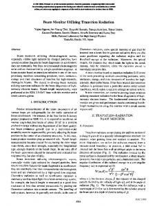
We have followed an alternative approach. Most MBE chambers use a Bayard-Alpert ionization gauge to measure the beam equivalent pressures from the effusion cells. We disconnected the beam flux monitor (BFM) from its controller and connected one or more of the pins to a Keithley 485 picoammeter, making a remote Langmuir probe. The input gas line to the plasma cell was grounded by design, providing the reference electrode. No changes were necessary inside the MBE chamber. This has the advantage of directly sampling the ions coming from the plasma, with no need to infer ion density from plasma conditions, optical spectra, or plasma cells mounted in dissimilar test chambers. Furthermore, the measurement can be made at the actual wafer position, unlike mass spectrometer based measurements. An ion gauge controller might be programmed or modified to perform this measurement directly, by turning off the filament and grid biases and measuring the current on the collector wire, but as we show later, the filament wire provides more signal than the collector wire does. We will show that the BFM-Langmuir probe presents a convenient and
2
III.
RESULTS
A typical Langmuir probe measurement from our cell is shown in Fig. 2. The highest energy ions ranged in energy up to approximately 35eV. Electron energies were under 8eV, consistent with reported values for rf plasmas.9 The extra inflection points at 9 and 12V, shown as the valley and second peak in the inset derivative plot, may indicate a bimodal distribution of electron or ion energies, but it is difficult to deconvolve the effects of ions, electrons, and secondary electrons in this range and geometry, and no attempt was made to compensate rf modulation of the
FIG. 1: Beam flux monitor as Langmuir probe.
3
Ion sat.
2
dI / dV (arb.)
4
Probe Current (nA)
powerful tool for the measurement of ion flux, and we will show the changes in ion current produced by changes in rf power, warmup time, and other variables. A careful reading of prior literature suggests the possible use of the BFM as a Langmuir probe, but this was not made explicit if it was indeed the case.7,10,11 Molnar et al. used the BFM to study an ECR plasma,12 but other applications have not been reported until recently, presumably due to several shortcomings which will be discussed below. We have recently become aware of another group which has reported a similar measurement,13 which appears to be an independent rediscovery of our previous reports.14 This technique was instrumental in the development of the first VCSELs on GaAs beyond 1450nm,15 and the longest wavelength room temperature, cw lasers on GaAs beyond 1500nm.16 In these experiments, an SVT Associates model 4.5 rf nitrogen plasma cell with a pyrolytic boron nitride crucible and aperture was used in a Varian Mod-Gen II MBE chamber for growth of GaInNAs(Sb). Unless otherwise noted, the gas flow was 0.5sccm of ultrapure nitrogen, and forward rf power was 300W. Because the nitrogen gas feedthrough is grounded, the plasma potential cannot be directly biased with respect to either the wafer or the BFM. Also, this MBE chamber does not have the capability of biasing the substrate to repel ions,5 so it is important to reduce the ion flux by some means, and to measure its effectiveness. To make this measurement, the BFM was disconnected from its controller, and a Keithley 485 picoammeter was connected between the BFM and ground. A voltage source, shown in Fig. 1, allowed separation of ion current from electron current. The BFM was mounted within a cylindrical metal shield, with an opening on the side facing the effusion cells. The bracket was grounded and served as a Faraday cage for the BFM in normal operation. Unless otherwise specified, only one wire on the BFM was used at a time, and the other wires remained unconnected, to minimize collection of secondary electrons.17 RF chokes and high-frequency capacitors prevented coupling of electromagnetic interference into the picoammeter. It should be noted that all ion flux measurements in this paper are relative, as it is difficult to determine absolute ion densities in this geometry.
8eV A
1 0
10
-1 -2
50
Electron saturation region
-3 -4 -5 -20
30
-10
35eV -10
0
10 20 30 Probe Voltage
40
50
60
FIG. 2: (Color online.) Langmuir probe measurement at beam flux monitor filaments. Saturated ion current, at A, is ∼1nA. The most energetic electrons and ions are 8 and 35eV, respectively. Inset: derivative of measurement.
plasma potential.18–20 The large slope of the saturation current is due to secondary electrons, and remains linear at higher voltages. The BFM has three parts: the collector wire, grid, and filaments. Any of these can be used for the Langmuir probe, and each has a different response, as shown in Fig. 3. The small size of the collector produced a weak signal, although it may be useful for spatially-resolved measurements. Because the collector is well shielded by the metal bracket, bias on the collector did not efficiently attract (focus) charges exiting the plasma at large angles. The filaments, on the other hand, are not shielded, so they can detect the nonzero plasma potential due to the plasma. The filaments also have a larger cross section, and are not shadowed by other parts of the ion gauge, so they collect more current: ∼1nA, compared to ∼10pA for the collector. This stronger current was easily measurable with an HP 34401A voltmeter with a 10MΩ input impedance, and agreed with the picoammeter. Fig. 3
3 8
14 Deflection Voltage
4
Grid
0
Collector x5
12 10 8 6
-4 Shield
Probe Current (nA)
Filament
-8 -10
4
Collector Filaments Grid mesh -5
2 0
5
10
-60
-50
-40
-30 -20 -10 0 10 Position (deg. above horiz.)
20
30
40
Probe Bias (V) FIG. 3: (Color online) Langmuir probe current using various wires on beam flux monitor. Offset for clarity. Arrow shows nonzero floating potential. Dashed lines measured immediately after plasma ignition; solid lines measured 15 minutes later. Inset: cross section of BFM.
Collector Current (pA)
50 25 0 -25 -50
-60
-40
-20
0 20 Grid Voltage
40
60
FIG. 4: Current through grounded collector wire vs. voltage applied to grid
also shows a decrease in ion density after the cell reached steady state. We also applied a DC bias to the grid of the BFM during the measurement to try to identify particular species in the plasma output.8 Fig. 4 shows the collected current as a function of grid bias, with the collector wire grounded. Contrary to the expected results, in which a positively-biased grid would repel positive charges and vice versa, the polarity of the grid bias matched the polarity of the collected current. This indicates that secondary electrons were being generated at the grid and/or collector, at a rate greater than the collection of charges from the plasma. The current dropped below the noise floor (∼1pA) when the plasma was extinguished, so this current was not merely leakage from the grid to the collector over some other conductive path. Since the grid is a very sparse mesh, the high biases may have also amplified the measured current through the Bayerd-Alpert process. In a Varian Gen II MBE system, the BFM ion gauge and the wafer carrier are mounted on opposite sides of a rotatable stage, or car, such that either the ion gauge or the wafer may be pointed toward the source furnaces.
FIG. 5: Position of peak ion current vs. deflection plate voltage. Probe is swept across beam by rotating the car, as shown at bottom.
The ion gauge is parallel to and approximately 7cm from the axis of rotation, so the gauge moves up or down as the car rotates to different angles. This allows spatial profiling of the beam, as shown at the bottom of Fig. 5. The upper portion of Fig. 5 shows a very approximate relation between the voltage applied to deflection plates, and the resulting angle of deflection. The discovery of an optimal range of deflection plate voltages will be reported elsewhere.21 For maximum spatial resolution in this measurement, the BFM collector wire was used for the probe, rather than the filament wires. The outlying data point at -28 degrees is believed to be due to shadowing of the ion gauge collector wire by a filament. Shadowing could be prevented by using the filament itself as the Langmuir probe, but with some loss of spatial resolution. The nonzero voltage offset is a result of the BFM collector being not quite centered in front of the plasma cell, and also the convolution of electron and ion currents. In principle, the measurement of Langmuir probe current with position could be used to verify the uniformity of the output from a plasma source in detail, such as studying the design of various aperture plates, but this was beyond the scope of this paper; no attempt was made to correct for shadowing or geometrical factors. Careful observation of nitrogen cells from several vendors has shown 15-20 minutes of instability before the plasmas reach a fully stable state, believed to be due to thermal processes in the cells.22 The instability is usually observed as minor changes in reflected power or optical intensity. We have verified that the ion current varies with time, particularly in the first few minutes, then is stable after that, as shown in Fig. 6. This has implications for comparison between groups, or wafer to wafer, as the plasma variation may lead to differences in ion damage, nitrogen incorporation, etc. If the plasma has not reached its stable operating point before the growth of multiple quantum wells, there may be significant differences between the quantum wells. Our method of overcoming this instability will be reported elsewhere.23
4
Ion Current (a.u.)
1.5
B 1
0.5
A Probe bias: -9V
0 10
30
50
70
90 110 Time (sec)
130
150
170
FIG. 6: Ion current vs. time, showing drift for several minutes after plasma ignition (A) and transition to high intensity mode (B). 0 Probe Current (nA)
0.75sccm 0.5sccm
-5
0.25sccm -10
-15 0
10
20
30 40 Probe Voltage
50
60
70
FIG. 7: (Color online) Langmuir probe measurement at several flow rates. Arrows mark the energy (eV) where current deviates from linear range, due to the highest-energy ions; error bars are approximately ±5V.
Also, there have been several reports of comparison of PL from samples grown with different plasma rf power or flow rate, assuming that the quality of XRD represented the optical quality of the material. However, the Langmuir probe shows that varying the flow rate can change the energy of incident ions, as shown in Fig. 7. The resulting change in ion damage and nonradiative recombination centers would not be easily detected by XRD, and the ion flux is more complicated than simple optical emission spectra would predict.6
IV.
DISCUSSION
It should be noted that this method fails to provide the detail of a conventional Langmuir probe, and care should be exercised before drawing conclusions about the plasma density or temperatures. The BFM is far from the interior of the cell, so it does not sample the ions within the plasma itself, nor a large fraction of the emitted ions. Also, the reference electrode consists of the gas supply line at the rear of the cell, which is some 6-8cm from the plasma itself, so there may be a significant potential drop
between the plasma and the reference electrode, leading to errors.24 Also, it is impossible to perform a longitudinal profile of the plasma by this method to extrapolate back to the plasma.17 Because of these restrictions and the probe geometry, estimates of electron and ion temperatures using the Laframboise method, for example, are generally not valid.25,26 Secondary electrons may also be generated from nearby surfaces by impact ionization17 or by photoemission, but in either case, the generation of secondary electrons even at low bias suggests that the plasma is energetic enough to cause ionization and ion damage to the wafer. Photoemission is is especially likely if the aperture holes are large enough to illuminate nearby metal surfaces with direct radiation from the plasma. Photons from N+ 2 , recombining N2 , and the metastable A3 Σ+ u state all have more energy than the workfunction of nearby metals.27 Whatever the origin, secondary electrons complicate the analysis of the I-V curve in several ways. First, the intermediate region, |V | < 30V, may be dominated by these lower energy electrons. This makes it very difficult to extract the ion or electron energy distributions. If the effect of secondary electrons could be eliminated, perhaps by applying a positive bias to the grid, it might be possible to extract the distribution of ion energies. The recent report by Miguel-S´ anchez indicates this may be a possibility.13 However, even with a biased grid, it is still possible for secondary electrons to interfere with the measurement, since they may be optically generated near the grid, as is believed to have happened in Fig. 4. The other effect of secondary electrons is to add a nonzero, linear slope to the I-V curve. This is taken into account by extrapolating from the linear region back to the floating-potential point (zero current). This slope appears to be qualitatively correlated with the optical brightness of the plasma. Nevertheless, using the BFM as a Langmuir probe provides an extremely useful measure of the actual ion flux at the wafer, which would seem to be the most pertinent information for plasma-assisted growth. In particular, the saturated ion current (point A in Fig. 2) and the energies of the most energetic ions and electrons (arrows in Fig. 7) can be unambiguously determined. Although the ion current varies with geometry and is only a relative measure, it is repeatable from run to run. It can be monitored in real time while adjusting the plasma parameters, such as rf power or flow rate, to produce a beam with the fewest ions. If an ion trap is available for the cell, the Langmuir probe can measure its effectiveness. Indeed, the Langmuir probe measurements have led to significant improvements in material quality, leading to the longest wavelength GaInNAsSb VCSELs and cw lasers to date. We had previously grown dozens of GaInNAs samples under varying conditions of growth rate, gas flow, and rf power to characterize the cell. Using the Langmuir probe, we were able to verify that our optimal conditions in fact led to the smallest ion flux while maintaining the efficient generation of atomic nitrogen based
5 on optical emission spectra. The remaining ions needed to be removed by deflection plates as noted above. The ability to characterize the plasma cell ion flux in real time allows optimizing the cell operation in a few hours, rather than the dozens of growths which were previously required. V.
SUMMARY
The beam flux monitor, a standard ion gauge in an MBE chamber, was used as a Langmuir probe, allowing the direct measurement of ion flux coming from a plasma cell, with no modifications necessary to the plasma cell or the chamber. The measured current was used to vary plasma operating parameters in order to minimize the ion damage to the wafer. Although the remote Langmuir probe cannot provide detailed information about the interior of the plasma itself, it nevertheless measures the relative ion flux which actually reaches the wafer. By us-
1
2 3
4
5
6
7
8
9
10
11
12
13
ing Langmuir probe measurements, we verified that our operation and changes to the cell were already nearly optimal, generating a minimum of ions while maintaining strong emission from atomic nitrogen. The plasma operating conditions to minimize ion damage no longer requires dozens of characterization growths, but can be studied in real time.
M. Kondow, T. Kitatani, S. Nakatsuka, M. C. Larson, K. Nakahara, Y. Yazawa, M. Okai, and K. Uomi, IEEE J. Selected Topics Quantum Electron. 3, 719 (1997). J. S. Harris, Semicond. Sci. Technol. 17, 880 (2002). A. J. Ptak, S. W. Johnston, S. Kurtz, D. J. Friedman, and W. K. Metzger, J. Crystal Growth 251, 392 (2003). P. Krispin, S. G. Spruytte, J. S. Harris, and K. H. Ploog, Appl. Phys. Lett. 80, 2120 (2002). V. Kirchner, H. Heinke, U. Birkle, S. Einfeldt, D. Hommel, H. Selke, and P. L. Ryder, Phys. Rev. B 58, 15749 (1998). T. Kageyama, T. Miyamoto, S. Makino, F. Koyama, and K. Iga, J. Cryst. Growth 209, 350 (2000). A. Ohtani, K. S. Stevens, and R. Beresford, Appl. Phys. Lett. 65, 61 (1994). T. H. Myers, M. R. Millecchia, A. J. Ptak, K. S. Ziemer, and C. D. Stinespring, J. Vac. Sci. Technol. B 17, 1654 (1999). J. Hopwood, C. R. Guarnieri, S. J. Whitehair, and J. J. Cuomo, J. Vac. Sci. Technol. A 11, 152 (1993). F. J. Grunthaner, R. Bicknell-Tassius, P. Deelman, P. J. Grunthaner, C. Bryson, E. Snyder, J. L. Giuliani, J. P. Apruzese, and P. Kepple, J. Vac. Sci. Technol. A 16, 1615 (1998). A. V. Blant, O. H. Hughes, T. S. Cheng, S. V. Novikov, and C. T. Foxon, Plasma Sourc Sci Tech 9, 12 (2000). R. J. Molnar, R. Singh, and T. D. Moustakas, J. Electron. Mater. 24, 275 (1995). J. Miguel-Sanchez, A. Guzman, and E. Munoz, Appl. Phys. Lett. 85, 1940 (2004).
Acknowledgments
The authors would like to thank Professor Mark Cappelli of Stanford University for helpful discussions. This work was supported under DARPA and ARO contracts MDA972-00-1-024, DAAD17-02-C-0101 and DAAD19902-1-0184, ONR contract N00014-01-1-00100, as well as the Stanford Network Research Center (SNRC) and a graduate fellowship from the National Science Foundation.
14
15
16
17
18
19
20
21
22 23
24 25
26 27
M. A. Wistey, S. R. Bank, H. B. Yuen, and J. S. Harris, 21st North American Conference on Molecular Beam Epitaxy, Keystone, Colorado (2003), p2.9. M. A. Wistey, S. R. Bank, H. B. Yuen, L. L. Goddard, and J. S. Harris, Electron. Lett. 39, 1822 (2003). S. R. Bank, M. A. Wistey, H. B. Yuen, L. L. Goddard, W. Ha, and J. S. Harris, Electron. Lett. 39, 1445 (2003). M. Schiller and W. Kulisch, Surf. Coat. Technol. 98, 1590 (1998). J. V. Scanlan and M. B. Hopkins, J. Vac. Sci. Technol. A 10, 1207 (1992). E. A. Edelberg, A. Perry, N. Benjamin, and E. S. Aydil, J. Vac. Sci. Tech. A 17, 506 (1999). A. P. Paranjpe, J. P. McVittie, and S. A. Self, J. Appl. Phys. 67, 6718 (1990). M. A. Wistey, S. R. Bank, H. B. Yuen, and J. S. Harris, Appl. Phys. Lett. (Submitted for publication). V. F. Gambin, private communication. M. A. Wistey, S. R. Bank, H. B. Yuen, L. L. Goddard, T. Gugov, and J. S. Harris, J. Vac. Sci. Tech.-B (Submitted for publication). J.-S. Chang, J. Phys. D 6, 1674 (1973). J. G. Laframboise, Tech. Rep. 100, Univ. of Toronto, Inst. Aerospace Studies (1966). R. M. Clements, J. Vac. Sci. Technol. 15, 193 (1978). A. J. Ptak, Ph.D. thesis, West Virginia University, Department of Physics, Morgantown, WV, USA (2001).