Using COMSOL Multiphysics to Modelling High Pressure Discharge. Lamps. J-B. Rouffet, S. Bhosle, G. Zissis, R. Ruscassié. Centre de Physique des Plasmas et ...
Excerpt from the Proceedings of the COMSOL Users Conference 2006 Paris
Using COMSOL Multiphysics to Modelling High Pressure Discharge Lamps J-B. Rouffet, S. Bhosle, G. Zissis, R. Ruscassié Centre de Physique des Plasmas et Applications Toulouse Université Paul Sabatier, 118 route de Narbonne, 31062 Toulouse
Abstract: This paper presents the using of Comsol multiphysics to model High pressure discharge lamps that are complex molecular systems. We take into account momentum, mass and energy conservation equations. All transport coefficients are computed and are depending of unknown parameters.
MTEP in western European level. This is done by means of fundamental and applied research in several domains (plasma physics and chemistry, materials, optics, power electronics and control science). Figure 1 summarizes the project structure.
Keywords: Multiphysics Fluid model, convection, electric field, interpolation, high pressure Discharge, Non-linear, instabilities
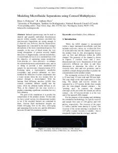
1. Introduction Highly efficient light sources are one route to help governments reduce the power consumption of lighting systems and hence reduce the emissions of greenhouse gases in line with the Kyoto agreements. A major area for lighting use is outdoor lighting, especially roadways and streets. The recent emergence of metal halide discharge lamps with ceramic arctubes has led to a new generation of highly efficient light sources with high colour rendering indices. Further lamp optimisation, coupled with improvements in the ballast characteristics and optical properties of the fixture, together with potential gains from sources specifically designed for human visual perception under mesopic lighting conditions have the potential to dramatically reduce energy usage in roadway lighting. Such systems would simultaneously improve the visual quality, energy efficiency and effectiveness of lighting schemes. ‘NumeLiTe’ is an EU supported project consisting of a consortium of 11 partners (industrial and academic) coming from 6 European countries exploring the feasibility of developing a new system for 21st century roadway lighting with a much improved energy. This project allowed the demonstration in real scale of a modern urban lighting scheme (121 lighting poles are installed in the city of Albi in south France). The project demonstrator illustrated that this system offers a better quality of life and security to road uses in urban environment coupled with important energy savings that may attain more than 1
Figure 1 NumeLiTe “system” approach
In parallel the research accomplished in the frame of NumeLiTe led to the creation of a suite of numerical tools used for optimising all system components. Thus more efficient, ceramic envelope metal halide lamps with 97 lm/W efficacy, supporting dimming without important degradation of their characteristics have been created
2 Our Work
electrode ceramic wall discharge
Figure 2 schematic lamp
The global modelling has to take into account several physical phenomena: chemical in high
Excerpt from the Proceedings of the COMSOL Users Conference 2006 Paris
u
g
u . u
m t .( m ) 0 m t p m . T mc p .T 2 U net .T t .V 0 with V
E
u
with
E
pM RT An e n Hg BT C
m U net
J.Appl.phys, 92, 2002
All transport coefficients are calculated with Matlab and saved in tabulates files that Comsol Multiphysics can read. The following Figure show the procedure used to solve the problem.
u
assumptions and fluid equations From Boltzman equations written for all particles of plasma, while integrating distribution functions on different velocity moments and while using Chapmann-Enskog formalism, we can describe the plasma with fluid equations system, with unknown factors: the velocity field u, pressure p, and temperature T.
.V 0 with E V
Finally, we can write: u
2.1 Plasma modelling and fluid equations
coefficient Unet. To know this field, we use Laplace equation:
u
temperature conditions, convection, energy conservation, etc. We have chosen FEMLAB (now COMSOL Multiphysic) because we need flexible software solving multiphysics problems with the finite elements method and easily implemented into Simulink. This last point has enabled us to take into account interactions with other components of the project.
2
u
E
u
T mc p .T t
g
u . u
u
m .( m ) 0 t p m . m t
U net .T
In these equations, it appears some transport coefficients: η is the viscosity coefficient. It controls convection within the arc tube and has a major influence on the power loss and hence the efficiency of the light source. σ represents electrical conductivity. The electrical conductivity of the plasma determines the voltage of the lamp and plays a vital role in the design of the ballast needed to control the electrical characteristics. and κ, the thermal conductivity; is another contributor to power loss and determines the wall temperature of the arc tube. The wall temperature is a key design parameter as it has a major influence on the failure mechanisms and life of the device. ρm represents the mass density of the fluid. These coefficients, taking into account the assumptions, are only depending on the pressure and the temperature and chemical composition. This system containing only 3 equations, it is necessary to make some assumptions. We thus suppose that the gas is perfect, which connects the mass density to the temperature and the pressure. In the equation system, it appears the electrical field E and the net emission
Figure 3: Construction of the model
2.2 Boundaries conditions To know properties of lamps plasma, it is necessary to solve the precedent equation system in the burner. But, before passing to the resolution itself, we have to define boundaries conditions on the unknown factors. In a first step, we can consider that the arc tube is a cylinder with a height of L and R for radius. Electrodes are also cylindrical (Figure 4).
Figure 4 simplified geometry
Excerpt from the Proceedings of the COMSOL Users Conference 2006 Paris
3
T=T2(z) T2(z) is given by u=0 M.Benilov
n.σE=j2 where j2 is given by M.Benilov
4
T=Tw
u=0
n.σE=0
5
T=Tw
u=0
n.σE=0
6
T=Tw
u=0
n.σE=0
7
T=T3(z) Where T3(z) is u=0 similar with T2(z)
V=0
8
T=T1
V=0
u=0
table 1. Boundaries conditions
j
Boundaries conditions on temperature: Electrodes being modelled by M.Benilov, we will use results of its simulations to know the temperature profile on the electrode surface. We suppose moreover an identical temperature, Tw, on all the walls of the burner. This temperature defines system pressure and much of properties of the fluid. Boundaries conditions on velocity field: We suppose that the velocity field is null on the wall and electrodes. Boundaries conditions on electrical field: The last one equation is on the potential V. M.Benilov's model gives current density on the cathode. Then boundaries conditions will be given on the current density: V . On the wall current is null, and we suppose that V=0 on the anode. To begin our study, we consider that the axe burner is parallel to the field of gravity, i.e. the lamp is placed vertically. This assumption makes it possible to simplify the model and to pass from 3 space dimensions to 2.
Results. In this section, we present results of our model for pure mercury lamp. Figures 6 shows temperature, electric and velocity field variation and in the arc.
Geometry and boundaries conditions. The revolution symmetry enables us to work with the following geometry 0,9cm wall electrode
6 7
figure 6 Temperature, velocity and potential in the burner in axisymetric case
8
g
With this model, we can predict: Wall temperature Area where corrosion can appears Plasma temperature and local composition. Geometry influence on the arc
7cm 1
5
2 3
chemical
4
0.1cm
Figure 5. diagram of the lamp Boundaries conditions are summarized in the following table. Boundary Condition number temperature 1
2
q.n=0 with
on
q T C p Tu
Condition Condition on on velocity potential n.u=0
T=T1 T1 is given by u=0 M.Benilov
n.σE=0 n.σE=j1 where j1 is given by M.Benilov
High Intensity Discharge lamps present several advantages over the other light sources (high efficacy, important lifetime, large power range) that made them undeniable for urban lighting applications. Since their consumption represent a non negligible part of the total energy amount consumed on earth, improvement on their efficiency and supply is obviously investigated. The power supply of discharge lamps is a key issue in improving lamp efficacy. However, depending on the power wave forms, some phenomena known as acoustic resonances can occur and involve arc instabilities, lifetime reduction and even lamp destruction.
Excerpt from the Proceedings of the COMSOL Users Conference 2006 Paris
Figure 7: example of arc distortion.
To study these phenomena better, we have developed an experimental setup mixing electrical, optical and acoustics measurements for ceramic metal halides lamps. This enabled us to identify frequencies for which we have acoustic resonances. We then have noticed that the distortion of the arc appeared only for certain frequencies. This sometimes involves a change in the production of the lamp radiation, and a phenomenon of hysteresis appeared according to whether the frequency increase or decrease. We then developed a fluid model in three dimensions coupling the conservation of mass, momentum, energy and current. The results that we obtain are in perfect agreement with those given by the experimental data and allow us to better understand the various phenomena responsible for these resonances but also their effects and in particular the amplitude of the oscillations. Starting with a model that we have developed and that has enabled us to optimise an industrial product, we have applied our results for this study. The first step was to determine fundamental modes of pressure vibration that can exist in the stationary case [1-2] (that means after having solved conservation of masse, momentum, energy and current equations with nonlinear coefficients [3-6]). We then can identify longitudinal, azimuthally, radial modes and combinations of those. Those frequencies have been compared with experimental results and we have seen a very good agreement.
Figure 8: example of a combination of azimuthally, radial, and longitudinal mode (3, 1, 1)
Considering a time dependant pressure excitation, we have resolved our equation system. We have observed a high dependence on convective flux that creates an arc distortion (for longitudinal even number – and nodistortion for odd number) similar with experimental results.
We can also predict precession of arc distortion or instabilities. These results represent a high step in the understanding of the acoustic resonances.
Figure 9: results on convective flow.
REFERENCES 1. “Numerical modelling of a DC current HID lamp for design purposes“, K.C. Paul, A. Erraki, T. Takemura, T. Hiramoto, F. Dawson, J-B. Rouffet, J-J. Gonzalez, A. Gleizes, and D. Lavers, 10th International Symposium on the Science and Technology of Light Sources, July 18-23, 2004, Toulouse, France. P491 2. “Defining Acoustic Resonances in Dimmed HID Lamps Using a Finite Element Model” R. Ruscassié, J-B. Rouffet, S. Bhoslé, G. Zissis, Ch. Glaize, proc. 40th IEEE Industry Applications Society Annual Meeting, 2-6 october 2005, Hong Kong (China). 3. “Two temperatures argon plasma model for thermal conductivities”, N.A. Harabor, J-B. Rouffet, G. Zissis, Annals of the university of Craiove, Physics AUC, volume 15 (part II), p32-37, Romania (2005) 4. “Modeling dynamic viscosity of Ar plasma in a two temperature regime”, N.A. Harabor, J-B. Rouffet, G. Zissis, M. Cristea, Annals of the university of Craiove, Physics AUC, volume 15 (part II), p38-42, Romania (2005) 5. “Net emission coefficient in plasma existing in high pressure metal halide lamps”, J.B.Rouffet, G.Zissis, Proc. 10th Int. Sympos. Science and Technol. Light Sources, pp. 287-288, 18-22 july 2004, Toulouse (France) 6. “Influence of Plasma Chemistry in High Pressure Ceramic Enveloppe Metal Hillide Lamps on the Mass Transport coefficients”, J-B. Rouffet, G. Zissis, M. Aubes, J-J. Damelincourt, 16th International Symposium on Plasma Chemistry, pp. 200, 22-27 june 2003, Taormina (Italy) 7. “Acoustic resonance prediction using a multiphysics model”, J-B. Rouffet, R. Ruscassié, S. Bhoslé, G. Zissis, Proc. 33st, IEEE International Conference on Plasma Science, 4-6 june 2006, Traverse City (USA).