a vision-based localization sensor with active naviga- tion. We explain the localization process, how its per- formance varies across the configuration space, and ...
Using Model-Based Localization with Active Navigation Amit Adam Dept. of Mathematics amitaQt x. technion.ac.il
Ehud Rivlin Dept. of Computer Science ehudr Qcs .t echnion.ac.il
Ilan Shimshoni Dept. of Industrial Engineering ilansQie.technion. ac.il
Technion - Israel Institute of Technology Haifa 32000 - Israel Abstract
of a positioning sensor across the configuration space. In this approach we consider the performance of the sensor together with two other important factors: the developing uncertainty in position, and the required level of localization. We use all these factors to plan sensing operations and actions which will enable the robot to navigate along its path. In the next sectioii we will motivate and describe the active navigation paradigm. We then describe our vision based localization method and how we estimate its different levels of performance at different configurations. Then we describe how we may optimally plan sensing operations along the path. The last section concludes the paper.
Vision is an important sensor used for mobile robot navigation. One approach to localization which is based on vision is to compute camera egomotion with respect to base images. What characterizes this method of localazation is that its performance varies greatly in different positions. Active navigation is an approach to path and sensing planning which is designed to address varying performance of a sensor across the configuration space. In this paper we describe how to integrate a vision-based localization sensor with active navigation. W e explain the localization process, how its performance varies across the configuration space, and the use of this variation by active navigation.
1
2
Introduction
2.1
The ability to navigate from one point to another is a fundamental requirement for an autonomous mobile
Background and Motivation
In previous works [la, 6, 8, 10, 13, 111 it has been recognized that the accuracy of the localization obtained by invoking a sensor, will in general depend on the configuration the robot is in. In other words, the combination of sensor and environment defines some kind of map which describes the quality of localization obtained at each configuration by using the sensor. It is then natural to try and plan the sensing operations to occur while the robot is in areas in which the sensors work well: according to the above mentioned map, the localization quality in these areas is good. Works which have considered this idea may be found in [12, 6, 81. In these works the motion planning algorithm uses the sensor performance map to plan paths. In [lo] a related notion is the information content of the environment at each Configuration. Another similar idea motivated by visual servoing is described in
agent. For mobile robots, odometry is a basic navigation tool. However because odometry errors accumulate over time, it is common practice to augment the robot with external sensors which are used for navigation. Among these, vision is an important sensor. In this paper we present the use of a vision sensor within the active navigation paradigm. One of the ways to use vision as a navigation sensor is to compute camera egomotion between images taken from the current configuration, and a base image taken from a fixed, known configuration. One advantage of this method is that it uses a small number of base images. However, for a fixed base image, at different positions of the robot we expect this positioning method to have different levels of success. In some positions with respect to base image the method might fail (because of occlusions for example), and in other positions it will work but with different levels of accuracy. This characteristic of the localization sensor motivates us to use it in conjunction with active navigation. Active navigation [l]is an approach to navigation which takes into account the varying performance level
0-7695-0750-6/00 $10.00 0 2000 IEEE
Active Navigation
[Ill. The motion planning approach taken in previous works (for example [ l a , lo]) is to search for a path in free space by minimizing a function which takes into account both the length of the path and the sensory uncertainty along the path. (The sensor performance
676
map has been termed Sensory Uncertainty Field (SUF) in [la]). This approach involves some arbitrary decision on how to trade off between sensory uncertainty and path length. These two different factors are usually combined into one objective function by introducing an arbitrary scale factor between the two. We suggest an alternative approach. In our approach we first consider the “nominal path” the robot has planned by using a specific motion planning algorithm. Had there been no practical problems such as odometry errors and inaccurate prior information, this “nominal path” is the path the robot would have executed. We then consider the localization accuracy required along the path. This accuracy is determined by the special characteristics of the path and the niotion planner which generated the path. This required localization accuracy, in addition to the sensory uncertainty field, affect our decisions on where the sensor should be invoked in order to update the position of the robot. To summarize, we may say that previous approaches strive for the highest localization accuracy possible and compromise on this accuracy in order to account for the length of the path. In our approach we strive for localization accuracy which is at the level required by the nominal path which was generated by the motion planner. Actions are needed by the robot in order to ensure that at all times the localization accuracy which is achieved by the robot is in agreement with the required localization accuracy.
2.2
I -\
Figure 1: U ( t ) - probability distribution of configuration at time t along the nominal path
model the position of the robot. The mean of the distribution is the nominal final position. The covariance matrix describes dispersion which is proportional to the length of the motion command. Its principal eigenvector is in the direction perpendicular to the heading direction, and the other eigenvector is in the heading direction. Fig. 1 shows an example of the development of uncertainty along the nominal path. A different model based on the triangular distribution may be found in [14].
2.4
The Factors Involved
Let us assume a motion planning algorithm (see for example [9]) has planned a path between the source configuration and the target configuration. Our robot intends to execute this “nominal” path. With the environment and the path we associate three factors: the uncertainty in configuration, the accuracy required in the answer obtained after a position (or configuration) update, and the level of accuracy in localization which is obtainable by using the sensor in the current configuration. We now elaborate on each of these factors.
2.3
Accuracy Requirement
We now consider the level of accuracy in position that is required from the sensor being used for position update. We consider the localization accuracy required in the context of performing a nominal path planned by a nzotaon planner. Let us view the nominal path as a sequence of straight line segments between “critical points”. Critical points are defined as points in the configuration space that the nominal path passes through. The points are chosen in a way that guarantees that between the critical points the robot may move in simple, straight line segments. The choice of critical points is dependent on the motion planner. Each motion planning algorithm is based on a different idea which in turn defines different critical points. We use two algorithms for motion planning to illustrate our definitions: the visibility graph algorithm and a cell decomposition algorithm [9]. In the visibility graph algorithm, the critical points are the vertices of the obstacles. It is guaranteed that from each vertex one may see the next vertex that is on the path. Hence motion between the critical points is indeed on simple, straight line segments. In the cell decomposition algorithm, we define the critical points as the mid-boundary points between the adjacent cells the nominal path passes through. It is guaranteed that the line segment between one point to
Uncertainty in Configuration
As the robot moves it keeps track of its current configuration. For various reasons (see for example [5]) uncertainty in the current configuration develops. We model this uncertainty as a probability distribution on the configuration space. Let U ( t ) be the probability distribution representing the configuration of the robot at time t along the nominal path. Different models have been suggested for the development of uncertainty in Configuration. For example we may use the Gaussian probability distribution to
677
3
Varying Performance Based Localization
of
Vision-
We now turn to discuss the last factor involved - the performance of the sensor. In general the performance of the sensor varies across the configuration space and hence we can think of a map which associates with each configuration the accuracy of the localization result obtained by using the sensor at that configuration. To illustrate this point, we will consider localization based on computation of camera motion based on several images. We assume that a camera is mounted on the robot. A base image is taken at a known configuration of the robot and camera. When localization is required, a second image is obtained. Point correspondences between the two images are found. From these correspondences the rotation and the direction of translation of the camera (w.r.t the base image configuration) may be found. In order t o estimate the magnitude of translation, the robot has to make a small move and obtain a third image. Since the camera is mounted on the robot, and since the base image configuration of the robot and camera are known, the current configuration of the robot may now be deduced. Details of this localization algorithm may be found in [3]. In [a] we have shown how to predict the uncertainty in the direction of translation resulting from this localization method. In the case of pure translation motion it is well known that the segments created by connecting pairs of corresponding points between the two images all lay on lines which meet at the Focus of Expansion (FOE). Thus the direction of translation (or FOE) may be found in principle by computing this intersection point from the given set of corresponding pairs. However, when the measured correspondences are noised, the lines on which the segments lay will not meet at one point. In this case we minimize an objective function which approximates a Maximum Likelihood Estimate for the FOE. See [a] for details. Let us now consider two different positions with respect to the base image. Fig. 3 shows the segments created by corresponding pairs between the base image and the images at the two different positions. The marks the location of the FOE in each case. It is intuitively clear that if the segments in Fig. 3(a) are perturbed a little, the FOE will move more than if the segments in part (b) of the figure will be perturbed. Thus the FOE computation is less stable in the first configuration than in the second. To obtain a quantitative measure of the dispersion of the FOE due to noise in the corresponding points, we used the linear approximation method presented in [TI. That work develops a method for computing the covariance of an estimator which is computed by minimizing
Figure 2: Critical regions in visibility graph and cell decomposition algorithms
the next is wholly contained in one cell. Hence it is guaranteed to be legal (i.e. not to collide with obstacles). We now note the following observation. We may extend the critical points to critical regions which contain more points that satisfy the assumptions on which the motion planning algorithm is based. Hence, in the visibility graph algorithm, there are other points around the vertex from which both the previous and the next vertex are visible. In the cell decomposition algorithm, there are additional points near the midboundary point which satisfy the two “algorithmic” requirements. Firstly they will lead us from the current cell to the next cell, and secondly we may reach them from the current point by moving along a segment contained in the current cell. These extensions of critical points to critical regions is illustrated in Fig.
2. The nominal path now clearly defines the accuracy requirements on localization, needed to guarantee completion of the path. Firstly, the robot should arrive with high probability in each of the critical regions. Secondly, in order to move between the critical regions, the robot should in principle just stick to the straight line segments connecting these regions. However, uncertainty in position may grow as long as the chances for collision with an obstacle stay low even with the uncertainty in position.
+
We stress the following point. The accuracy requirements are different in various regions of the configuration space, and for various nominal paths. For example, consider a path planned by a cell decomposition algorithm. In areas where the cells are large and have large boundaries between them, the critical regions are large. Hence the localization accuracy required is not very high. In other regions near obstacles, where cells are bound to be smaller, a higher localization accuracy may be required.
678
Figure 5: Base image translation (b)
Figure 3: An example of (a) unstable and (b) stable configurations
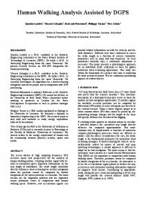
Figure 4: Uncertainty in direction of translation, as a function of position with respect to the base image. (a) Predicted uncertainty. (b) Empirical measure of dispersion. The graph shows the 9O’th percent quantile of the 3D angular error distribution at each configuration.
and image after forward
Figure 6: Predicted vs. empirical dispersion
gle between the principal axes of the two ellipses is 11.9 degrees. The ratios of the lengths of axes are 1.01 and 1.08. As is evident by these numbers and by looking at the figure, the prediction is quite accurate.
an objective function. We applied that method to the objective function we use for computing the FOE. As an example we refer to Fig. 4. Here the base image was taken from position (0,O). For each new position (X, Y ) ,we have estimated the error in determining the direction of translation to the new position. The theoretical prediction is shown in the left figure. In the right figure we show the empirical results. The 90’th percent quantile of the angular error in direction, is plotted as a function of position with respect to the base image. Clearly we can see that the empirical results agree with the predicted map. As another example, consider the images in Fig. 5 taken in our lab. Around 30 pairs of corresponding points were found. Based on these points, the FOE was computed and its dispersion predicted by our method. These predictions were then compared to the dispersion of FOE values obtained by minimizing the objective function on noised versions of the point correspondences. Figure 6 shows the actual dispersion of 50 FOE estimates, and the dispersions described by the predicted and empirical covariance matrices. The an-
4
Planning Updates Along the Route
We will now describe an example of using the active navigation paradigm and the performance map derived above for the vision sensor. Our robot uses the visibility graph method to plan paths in the work space. The planned path in this method passes through the vertices of the obstacles. As described previously, the accuracy requirement in this case defines critical regions around these vertices. Consider now the position uncertainty but only in the direction which is orthogonal to the heading direction. Let us assign a single number to measure this uncertainty - for example 3 standard deviations. This uncertainty grows linearly according to our model. The distance from obstacles and the size of the critical regions define its maximum allowed value. This maximum allowed value changes along the route and is actually a piecewise constant function. We now compute the uncertainty in direction of translation with respect to two given base images, by the method described above. This allows us to infer the maximal uncertainty
679
for all i 5 t 5 j then the no updates are necessary and f(u;i , j ) = 0. Otherwise, f(u; i, j ) may be computed recursively as
in localization that will be obtained in the direction we are interested in. See Fig. 7. Hcadmg h u m
I
Using the method of dynamic programming an efficient computational scheme may be employed to find the optimal times at which updates should be made.
5
E m
Discussion
When considering vision as a sensor for mobile robot localization, one cannot expect to obtain the same level of performance uniformly over the work space. The active navigation paradigm is an approach which is designed to address this rather common characteristic of localization sensors. In this paper we have shown how we may use a vision sensor and the active navigation approach to plan sensing along the route, in a way which will allow a robot to successfully navigate along the route, while keeping the sensing cost to a minimum. So far we have addressed the uncertainty in the direction of translation. There are additional issues which affect vision-based localization performance. An important example of such an issue is the variance in ability to find corresponding points between the images. We plan to address this question in future work.
baw m g c
Figure 7: Allowed vs. obtainable uncertainty We now let U,, ( t ) denote the maximal uncertainty allowed, and U,.(t) denote the uncertainty we will obtain by using the two base images. Let U ( t ) denote the linearly growing uncertainty in position. At all times, the uncertainty U ( t ) should be less than U n ( t ) . Assume a position update at time t costs C ( t ) . The problem is to find times of update tl ,t 2 , . . , which will ensure that U ( t )L U n ( t )
References [l]
for t = 1 , 2 , . . . , T , and this with minimal cost of update operations. Fig. 8 illustrates this problem. This
A m i t A d a m , E h u d Rivlin. a n d Ilan S h i m s h o n i . Active navigation, 1999. In preparation.
[Z] A m i t A d a m , E h u d Rivlin, a n d Ilan S h i m s h o n i . C o m p u t i n g t h e sensory u n c e r t a i n t y field of a vision based localization s e n s o r . I n Proc. IEEE In1 C o n f . o n R o b o l r e r e n d A u l o m a l a o n , 2000. To a p p e a r . [3] R. Basri, E. R i v l i n , a n d I . S h i m s h o n i . Visual h o m i n g : S u r f i n g on t h e cpipoles. I n l e m o l r o n o l Jorrnol of C o m p d e r Vrsron, 33(2), 1999. [4]
R. E. Bellman a n d S . E . Dreyfus. A p p l i e d D y n a m i c Programming. P r i n c e t o n University Press, 1962.
[5]
J . B o r e n s t e i n , H . R . E v e r e t t , L . Feng. a n d D. Wehe. Mobile r o b o t posit i o n i n g : Sensors a n d t e c h n i q u e s . Jovrnol of R o b o t i c Syrlems, 14(4):231-249, 1997.
[6]
T. Fraichard a n d R. Mcrmond. P a t h p l a n n i n g with u n c e r t a i n t y for carlike r o b o t s . In Proc IEEE Inl. Conf. o n 1998.
Robotics and Aulomolron,
pages 27-32,
[7] R. M. Haralick. P r o p a g a t i n g covariance in c o m p u t e r vision. 22'lh I C P R , pages 493-498, 1994.
In Proc
of
[e] A.
L a m b e r t a n d N . L. F o r t - P i a t . Safe a c t i o n s a n d observation p l a n n i n g for mobile r o b o t s . In Proc. IEEE I n l . C o n f . o n R o b o l i e i and A r l o m o l i o n , pages 1341-1346, 1999.
Figure 8: Find times for update actions which will ensure completion of the path with minimal cost (see text)
[9]
[lo] N . Roy, W. B u g a r d , D. Fox, a n d S . T h r u n . C o a s t a l navigation
+ a(t - i )
-
mobile r o b o t navigation w i t h u n c e r t a i n t y in d y n a m i c e n v i r o n m e n t s . In Proc IEEE I n l . C o n f . o n R o b o l i c r o n d A u l o m o l i o n , pages 35-40, 1999.
[ll] R. S h a r m a a n d H. S u t a n t o . A f r a m e w o r k for r o b o t motion p l a n n i n g with sensor c o n s t r a i n t s . IEEE Tronruelions o n Robolrer and A u l o m a l i o n , 13(1):61-73, F e b r u a r y 1997.
problem may be solved by the dynamic programming approach (see for example [4]). Let f ( u ; i , j )denote the cost of reaching from t = i to t = j with initial uncertainty U at time t = i . Let the uncertainty U ( t ) grow linearly with slope a. If U
J e a n - C l a u d e L a t o m b e . Robol Molron Plonnrng. K l u w e r Academic P u b l i s h e r s , 1991.
[12] H. T a k e d a , C. F a c c h i n e t t i , a n d J . C . L a t o m b e . P l a n n i n g t h e m o t i o n $ of a mobile r o b o t in a sensory u n c e r t a i n t y field. IEEE Transorlion' o n P o l l e r n A n o l y i i r a n d M o c h r n c Inlcllcgence, 16(10):1002-1017, O c t o b e r 1994. [I31 S . T h r u n . F i n d i n g l a n d m a r k s for mobile r o b o t navigation. In P r o r . IEEE Inl. Conf o n R o b o l i c s a n d A w I o m d a o n , pages 958-963, 1998. [14] S . T h r u n , W . B u g a r d , a n d D. Fox. A probabilistic a p p r o a c h t o c o n c u r r e n t m a p p i n g a n d localization for mobile r o b o t s . A u l a n a m o u s R o b a l i , 5:253-271, 1998.
Un(t) 680