APPLIED PHYSICS LETTERS 91, 013505 共2007兲
Using the temperature dependence of resonator quality factor as a thermometer M. A. Hopcroft,a兲 B. Kim, S. Chandorkar, R. Melamud, M. Agarwal, C. M. Jha, G. Bahl, J. Salvia, H. Mehta, H. K. Lee, R. N. Candler, and T. W. Kenny Department of Mechanical Engineering, Stanford University, Stanford, California 94305 and Department of Electrical Engineering, Stanford University, Stanford, California 94305
共Received 21 March 2007; accepted 11 June 2007; published online 3 July 2007兲 Silicon micromechanical resonators have been designed to have a quality factor 共Q兲 that is a strong function of temperature. This is an ideal sensor for the temperature of the resonator—it is instantaneous, consumes no power, and indicates the temperature of the resonator structure with high sensitivity. The authors present a practical implementation of an oscillator system using these resonators with a temperature resolution of better than 0.002 ° C. The Q共T兲 signal is uniquely suited for implementing feedback control of the resonator temperature, thereby stabilizing the frequency silicon micromechanical resonators and enabling their use in high-stability frequency reference applications. © 2007 American Institute of Physics. 关DOI: 10.1063/1.2753758兴 Frequency references, devices which supply a constant frequency signal, are an essential component in every electronic system. Microprocessors require a clock frequency, radios need channel specifiers, navigation systems need timekeeping, etc. Oscillators based on quartz crystal resonators dominate the frequency reference industry, especially in high performance applications. However, quartz-based devices suffer from a number of disadvantages which limit their potential size and cost reductions. Silicon resonators, desirable for their potential for integration with complementary metal-oxide semiconductor 共CMOS兲 circuits, have long been considered as candidates for replacing quartz.1 However, only recently have advances in silicon microelectromechanical system 共MEMS兲 technology enabled silicon resonators to be fabricated with the long-term stability required for frequency references.2,3 Since the long-term stability of the resonators has been established, the next challenge for designing silicon frequency references is their temperature sensitivity. Silicon resonators have an inherent frequency-temperature 共f-T兲 sensitivity of approximately −30 ppm/ ° C, or nearly 4000 ppm over a −40 to 85 ° C operating range. High performance quartz systems4 may have a f-T value of 0.04 ppm over the same temperature range, which is achieved by packaging the oscillator in a temperature-stabilized enclosure 共“ovenizing”兲. Ovenizing is also required for high performance silicon devices, and temperature stabilization requires a temperature sensor whose output signal is suitable for feedback control. However, it is quite difficult to integrate conventional temperature sensors, such as thin-film resistance temperature detectors or CMOS diodes, into the MEMS fabrication process, which involves temperature cycles of 1000 ° C or more.2 External temperature sensors cannot provide the performance required for the desired level of temperature control because of the inevitable offsets and time delays due to the physical separation between the sensor and the resonator. To address this need, we have designed resonators whose quality factor 共Q兲 is a strong function of temperature.5 The resonator Q is almost an ideal temperature sensor—it a兲
Electronic mail:
[email protected]
consumes no additional power, has no time delay or hysteresis, and indicates the temperature of the resonator directly. However, Q measurement, while straightforward in resonators, is not trivial in oscillators. In this letter, we present an implementation of a MEMS-based oscillator system that can extract the Q共T兲 temperature sensor signal from the oscillator output with millidegree resolution in a multihertz bandwidth. The quality factor of a resonator is defined as the ratio of the energy stored in a system to the energy dissipated per radian of the vibration cycle,
Q = 2
Estored Edissipated/cycle
.
共1兲
Four types of damping are usually associated with micromechanical resonators: air damping, thermoelastic dissipation 共TED兲, anchor loss, and surface loss. When multiple damping mechanisms contribute to energy loss, the Q can be expressed as the inverse sum of the individual mechanisms, 1 1 1 1 1 + + + . = Q Qair QTED Qanchor Qsurface
共2兲
The resonators described in this work are electrostatically operated double-ended tuning forks 共DETF兲 with dimensions shown in Fig. 1. For these resonators, the dominant energy loss mechanisms are well understood: the resonators are encapsulated in a low pressure environment, so air damping is small; the tuning fork design minimizes anchor loss, and the dimensions are relatively large so that the surface-tovolume ratio is low and surface losses are negligible. However, the loss from thermoelastic dissipation 共TED兲 is significant and dominates the resonator Q value.5,6 TED is the energy loss due to heat transport between regions of the resonator beam which change temperature when the beam flexes, compressing or stretching different areas of the beam.7 This mechanism depends strongly on the material properties of the silicon beam 共thermal expansion, density, heat capacity, and thermal conductivity兲, all of which change with temperature. We can describe the resulting temperature dependence of QTED with a temperature coefficient of Q parameter,8 ␥,
0003-6951/2007/91共1兲/013505/3/$23.00 91, 013505-1 © 2007 American Institute of Physics Downloaded 03 Jul 2007 to 128.32.55.8. Redistribution subject to AIP license or copyright, see http://apl.aip.org/apl/copyright.jsp
013505-2
Appl. Phys. Lett. 91, 013505 共2007兲
Hopcroft et al.
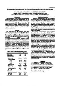
FIG. 3. 共Color online兲 Oscillator output amplitude vs temperature.
FIG. 1. Silicon MEMS double-ended tuning fork 共DETF兲 resonator. The beams of the tuning fork move in plane between the electrodes.
Q⬀
1 . T␥
共3兲
Larger ␥ indicates a higher sensitivity of Q to temperature. The value of ␥ for the resonators discussed here is ⬃2.7. The Q of a resonator is normally measured with gainphase frequency-domain measurements or ring-down timedomain measurements. Neither method is suitable for highresolution, high-bandwidth measurements required for control applications. Moreover, frequency references require oscillators, and neither gain-phase nor ring-down information is available from the oscillator output signal, which 共ideally兲 consists of a sine wave at a fixed frequency. Therefore, we need to measure resonator Q indirectly. We can solve the standard second-order system model of a mechanical resonator to show that the amplitude of vibration, X0, at the resonant frequency f 0 is proportional to the Q, F = mx⬙ + bx⬘ + kx ⇒ Q = 2
f 0m , b
X0 =
FQ , k
共4兲
where m, b, and k are the mass, damping, and spring constant terms, respectively. The output transduction mechanism for our resonators is capacitive, so that if the beam displacement increases for the same frequency of vibration, the amplitude of the output signal, Vout, increases proportionally, Vout ⬀
dC ⬀ X0 , dt
共5兲
where C is the transduction capacitance. When the resonator is operated in an oscillator, the amplitude of the oscillator sine wave output reflects the resonator vibration amplitude. Therefore, if we can design an oscillator circuit that maintains a constant amplitude input signal to the resonator, then
the amplitude of the oscillator output will directly reflect the resonator Q value. Our preliminary oscillator circuit topology is shown in Fig. 2. A clamping amplifier with clamp levels set much lower than the lowest expected amplitude after the gain stage is used to hold the input voltage to the resonator at a constant level. The output amplitude of this circuit, as measured by a Hewlett-Packard 89410A signal analyzer, is shown in Fig. 3, and the corresponding noise density spectrum is in Fig. 4. In temperature sensor applications, it is common to apply a low-pass filter to the sensor signal in order to reduce the effects of noise. The resulting minimum detectable temperature change, known as the temperature resolution, can be estimated by integrating the square of the signal noise density up to the filter cutoff frequency, then taking the square root and dividing by the sensitivity. The sensitivity and noise values for the output amplitude are −1.4⫻ 10−3 V / ° C and 5.26⫻ 10−6Vrms in a 1 Hz bandwidth 共at the lowest frequencies兲, resulting in a temperature resolution of 0.0035 ° C. This is a reasonably good temperature resolution and it indicates that the proposed method is functional. A more practical measurement method was realized by inserting a discrete broadband root-mean-square 共rms兲 level detector at the output of the oscillator 共Fig. 2兲. The rms detector output is a dc voltage with a conversion gain of 7.5 V / Vrms.9 The output of the rms detector has a worse noise figure than the amplitude of the oscillator output but the increase in sensitivity due to the conversion gain compensates for it. The rms detector output is also shown in Figs. 3 and 4, and it has a sensitivity of −9.4⫻ 10−3 V / ° C and a noise density of 1.16⫻ 10−5Vrms in a 1 Hz bandwidth. The resulting temperature resolution in a 1 Hz bandwidth is 0.0017 ° C. Even after doubling sensor bandwidth to allow a temperature control system to operate reliably at 1 Hz, the temperature resolution is 0.0026 ° C.
FIG. 4. 共Color online兲 Q共T兲 signal noise density. The shape of the noise density of the amplitude as measured by the analyzer reflects the characterFIG. 2. 共Color online兲 Oscillator circuit topology. The clamping amplifier istic of the gain stage in the oscillator. The shape of the plot from the rms ensures that the input to the oscillator has a constant amplitude. detector is defined by the low-pass output filter. Downloaded 03 Jul 2007 to 128.32.55.8. Redistribution subject to AIP license or copyright, see http://apl.aip.org/apl/copyright.jsp
013505-3
Appl. Phys. Lett. 91, 013505 共2007兲
Hopcroft et al.
This result is promising, and there is room for improvement in several areas. First, the silicon MEMS resonator is CMOS compatible, and we would expect that oscillator circuitry integrated with the resonator would have lower noise. The rms detector is a commercial broadband device 共designed for mobile phone frequencies兲 which is integrating signal amplitudes at all frequencies up to 2.5 GHz,9 and optimizing its design for the frequencies of interest should improve the noise performance. The DETF resonator design can be optimized to minimize amplitude-frequency interactions10 共reduce noise兲 and to increase ␥ 共improve sensitivity兲. It is also true that the use of clamping amplifiers in the oscillator 共Fig. 2兲 introduces more noise than using comparable variable gain amplifiers for automatic gain control 共AGC兲. The Q共T兲 temperature measurement could easily be implemented in an oscillator with AGC by using the gain control feedback signal as the indicator of the resonator temperature. A practical method for measuring the temperature of a silicon MEMS resonator in an oscillator system with high resolution and bandwidth has been demonstrated. Temperature resolution of better than 0.002 ° C in a 1 Hz bandwidth has been achieved, and further improvements are possible. Use of this oscillator Q共T兲 signal as a temperature sensor has not been reported previously. A resonator with an f-T value of −30 ppm/ ° C held to this level of temperature stability will have frequency stability of better than 0.1 ppm over the range of operation. Our next-generation oscillator circuits are expected to increase the temperature resolution further, and fabrication techniques are being developed that will reduce the resonator f-T value.11 The combination of these technologies will enable silicon-based frequency references that achieve performance comparable to high-end quartz products.
This work was supported by DARPA HERMIT 共ONR N66001-03-1-8942兲, the National Nanofabrication Users Network facilities funded by the National Science Foundation under Award No. ECS-9731294, the National Science Foundation Instrumentation for Materials Research Program 共DMR 9504099兲, and the Robert Bosch Corporation. The authors would like to acknowledge strong support and advice for this work from G. Yama, A. Partridge, M. Lutz, C. Nguyen, J. Vig, B. Murmann, R. Howe, and K. Goodson. 1
C. T. C. Nguyen and R. T. Howe, IEEE J. Solid-State Circuits 34, 440 共1999兲. 2 R. N. Candler, M. A. Hopcroft, B. Kim, W. T. Park, R. Melamud, M. Agarwal, G. Yama, A. Partridge, M. Lutz, and T. W. Kenny, J. Microelectromech. Syst. 15, 1446 共2006兲. 3 B. Kim, R. N. Candler, M. A. Hopcroft, M. Agarwal, W.-T. Park, and T. W. Kenny, Sens. Actuators, A 136, 125 共2007兲. 4 Vectron Inc., “C4500 Ovenized Crystal Oscillator 共OCXO兲,” in Vectron, Inc. Product Catalog, 2006. 5 R. N. Candler, A. Duwel, M. Varghese, S. A. Chandorkar, M. A. Hopcroft, P. Woo-Tae, K. Bongsang, G. Yama, A. Partridge, M. Lutz, and T. W. Kenny, J. Microelectromech. Syst. 15, 927 共2006兲. 6 A. Duwel, R. N. Candler, T. W. Kenny, and M. Varghese, J. Microelectromech. Syst. 15, 1437 共2006兲. 7 C. Zener, Phys. Rev. 52, 230 共1937兲. 8 B. Kim, C. M. Jha, T. White, R. N. Candler, M. A. Hopcroft, M. Agarwal, K. K. Park, R. Melamud, and T. W. Kenny, Proceedings of the 19th IEEE International Conference on Micro Electro Mechanical Systems, Istanbul, Turkey, 2006. 9 Analog Devices part AD8361, TruPwr™ 2.5 GHz rms detector, in Analog Devices Product Catalog, 2006. 10 M. Agarwal, S. A. Chandorkar, R. N. Candler, B. Kim, M. A. Hopcroft, R. Melamud, C. M. Jha, T. W. Kenny, and B. Murmann, Appl. Phys. Lett. 89, 214105 共2006兲. 11 R. Melamud, B. Kim, S. A. Chandorkar, M. A. Hopcroft, M. Agarwal, C. M. Jha, and T. W. Kenny, Appl. Phys. Lett. 90, 244107 共2007兲.
Downloaded 03 Jul 2007 to 128.32.55.8. Redistribution subject to AIP license or copyright, see http://apl.aip.org/apl/copyright.jsp