Available online at www.sciencedirect.com
Procedia Engineering 41 (2012) 777 – 783
International Symposium on Robotics and Intelligent Sensors 2012 (IRIS 2012)
UTHM HAND: Performance of Complete System of Dexterous Anthropomorphic Robotic Hand Amran Mohd Zaid*, M. Atif Yaqub Faculty of Electrical and Electronics Engineering, University Tun Hussein Onn Malaysia, 86400 Parit Raja, Batu Pahat, Johor, Malaysia.
Abstract This paper describes a new robotic hand system working under master slave configuration. The slave robotic hand is tele-operated by a master glove that a human operator can wear. The wireless tele-operation is being done by using Bluetooth as the communication channel between master and slave. The angle information of the operator’s hand is transferred via this Bluetooth channel by embedding BendSensors in the glove. BendSensors act like a potentiometer strip and detects the movement of every joint present in the hand. The slave robotic hand, on reception of this angle information mimics the movement of human operator. The UTHM robotic hand is a multi fingered dexterous anthropomorphic hand. The hand comprises of five fingers (four fingers and one thumb), each having four degrees of freedom (DOF), which can perform flexion, extension, abduction, adduction and also circumduction. For the actuation purpose, pneumatic muscles and springs are used. The paper exemplifies the design for the robotic hand and provides the torque modelling and torque produced at each finger joint of the robotic hand. It also discusses different robotic hands that have been developed before date.
© 2012 The Authors. Published by Elsevier Ltd. Selection and/or peer-review under responsibility of the Centre of Humanoid Robots and Bio-Sensor (HuRoBs), Faculty of Mechanical Engineering, Universiti Teknologi MARA. Keywords: Robotic hand, Tele-operation, Multi-fingered hand, pneumatic muscles, solenoid valves.
Nomenclature fmuscle fspring F Fmax T0 TT f f_|_ f|| ffinger segment
The force applied by the pneumatic muscle on the joint The force applied by the spring Flow rate Maximum flow rate of valve ON time of signal Time period of signal Force Perpendicular component of force Parallel component of force Force applied on the finger segment
1. Introduction Robots have become an integral part of modern human life. With every passing year the population of robots is being increased. The industry has replaced a large number of human workers with lesser number of robots on the grounds of
* Corresponding author. Tel.: 00607-4538305; fax: 00607-4536060. E-mail address:
[email protected]
1877-7058 © 2012 Published by Elsevier Ltd. doi:10.1016/j.proeng.2012.07.243
778
Amran Mohd Zaid and M. Atif Yaqub / Procedia Engineering 41 (2012) 777 – 783
economy and efficiency. A robot is a modern version of slave, which perform any task in its capacity satisfying the old human instinct to rule. A robot follows the command as ordered by the human master. Therefore the humans can still enjoy mastering a dumb but efficient slave under their supremacy. The intelligence of humans has been linked to the hands. Aristotle and Anaxagoras had been discussing this association hundreds of years ago [1]. Humans are the only specie that has been gifted with this kind of dexterous hands, where the universe of full of various species. These hands are capable of doing so many tasks in our routine like dexterously handling different things and even sensing. Therefore this has been discussed from long to be one of the reasons that humans are so intelligent. The human hand consists of fifty four bones whereas the complete body of an adult human contains two hundred and six bones [2], which is around 26% of the total human bones. When discussing the robotic hands, the segments or parts that join together to build the robotic hand are mostly less than this number. Even after reaching this number, it cannot compete with the human hand in a broad range of tasks. The reason is the structure of human hand and the material used in human hand that cannot be compared by the material available for robotic hands. The toolset and materials of Mother Nature is far advance than any of the latest technology. The population of robots and robotic hands is being observed to be increasing gradually throughout the industry. Robots are replacing the erroneous human operators in the industrial processes at a fast speed as more automation is being applied in the industry. The robots working in industry do not make mistakes that can be expected from humans, they are faster, more accurate and their speed is consistent as well. While in some cases the robots are a necessity, because of the working environment or the tasks. For example in the cutting industry, a human operator is in danger as the high speed cutters possess danger for the operator, or in the high temperature environments, like the rubber factories, humans are exposed to burn injuries. A robotic hand system has been developed that is perfectly compliant to the needs of industry and the hand alone can also be used in prosthetics and rehabilitation. The shape, size and weight of the hand is comparable to actual human hand, therefore it is an anthropomorphic hand. The robotic hand is very flexible so that it can attain dexterous manipulation and can pick and place different things of different shapes and sizes like a normal human hand. The complete system should be able to fix the reprogramming issue and reduce the human injuries in extreme environments. 2. Literature Review The research on robotic hands is being done for a long period of time. Looking back to the history of robotic hands, in 1961 Heinrich Ernst developed for the first time, the MH-1 a computer operated mechanical hand at MIT [4]. This hand was a gripper that used two fingers to pick and hold some blocks using electric motors as actuators and touch sensors for the object identification. Grippers are mostly application specific robots and they do not tend to copy the complete properties and characteristics of actual human hand. The finger count for the grippers ranges from two to three fingers, which results in a low DOF that does not make the robot hand able to act dexterously. Theoretically the least number of DOF to achieve dexterity in a robotic hand with rigid, hard-finger, non-rolling and non-sliding contacts, is nine [5]. The proof for this theory was the development of Stanford/JPL hand. Many research works had been done on grippers [6], [7], [8], [9], [10], [11], [12] and many companies started production of grippers. Universities, automotive companies, other industries and even space programs for some countries are the customers to these gripper companies. The concentrated research work for grippers was done in 1980s and early in the decade of 1990 the idea for gripper was well established. The development of MIT/UTAH hand [13] was the beginning of more complex robotic hand structures. It was the first robotic hand capable of dexterously manipulating objects. It had four fingers and over twenty five DOF including the wrist joint. Much research work has been done in dexterous manipulation performed by robotic hands and highly manoeuvrable and anthropomorphic hands have been reported. A detailed study on the robotic hands performing dexterous manipulation can be seen in [3]. Researchers had been using electrical, mechanical and hybrid actuation schemes for the robotic fingers. But every actuator has its limitations and restrictions like the space required for the actuator sometimes causes the hand size to go bigger than the actual human hand. Sometimes the actuator system needs to be placed outside the hand making it an extrinsic type of robotic hand. The force applied by the fingers is limited for the intrinsic type of robot hands where the actuator system is placed inside the fingers. The choice of design to be extrinsic or intrinsic depends on the application of robotic hand. If the hand is required to be anthropomorphic with no extra outer components then intrinsic design is preferred whereas extrinsic design can be useful in applications which require high precision and even the vibrations of the hand is not tolerable. With the extrinsic design the researchers can get the maximum DOF as there is no such restriction for size. In order to actuate the finger joints in the robotic hand artificialitists has been using electric motors quite frequently [14],
Amran Mohd Zaid and M. Atif Yaqub / Procedia Engineering 41 (2012) 777 – 783
779
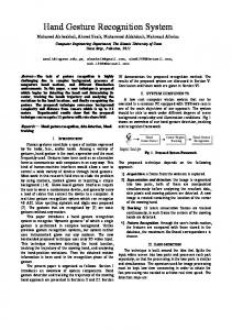
[15], [16], [17], [18]. Electric motors have been proved to be very accurate in position and velocity control and also provide much force for the grasping function required by the robotic hand. The use of electric motor also simplifies the mechanical design of the hand. In the use of electric motors, several approaches have been presented such as attaching the motors directly to the joints avoiding the extra mechanics involved; using tendon cables with motors, using tendon cables and pneumatic actuators, using gearing with motors and others are the hybrid of these approaches. The MIT/UTAH hand had three fingers and one thumb [13]. They removed the little finger to avoid complexity in their dexterous robotic hand. Each finger had four DOF and four joints and each joint is separately controlled by a pair of tendon cables. Pneumatic actuators were used for the finger movements. The digital control systems comprises of five Motorola 68000 microprocessors, forty DAC channels and three hundred and twenty ADC channels. NASA's Robonaut Hand had twelve DOF and five fingers like human hand [19]. Brushless DC motors and gear head were used for the finger actuation. The motors were placed outside the hand for keeping the size of hand small. The mechanical design for these fingers was very complex and putting them altogether inside was much difficult task. The anthropomorphic NTU hand had seventeen DOF with five fingers and was comparable to the size of human hand [20]. This hand had very complex gearing involved in its fingers as it had a special set of arranged gear trains present in for every joint along with a smart motor that was performing the joint actuation. Similarly the DIST-Hand was developed with sixteen DOF and high level of dexterity [21]. It had four fingers actuated by tendon drive and DC motors. The DLR-Hand also used dc motors with transmission tooth belt and harmonic drive gears [22]. The digital control system was based on two Motorola 68040 based CPU boards, ADCs, hall sensors and potentiometers. Compact fluidic hand had been developed and reported with fourteen DOF [23]. The hand is powered by fluidic actuators and a miniaturized hydraulic system was developed to be embedded inside the robot hand. The Keio hand had been developed having twenty DOF almost the same as human hand [24]. This hand has been actuated uniquely using ultrasonic motors along with elastic elements. Another unique design using spring as actuating element has been reported [25]. The said robot had three fingers and was reported achieve very high acceleration. This robotic hand was reported for capturing purposes. 3. Master Glove The control of the under discussion robotic hand is done by using tele-operation. For the actuation of anthropomorphic and dexterous robotic hand, all the angles of finger joints of the human operator must be tracked. Tracking of angles is done by a special glove, which is embedded by BendSensors and it is also capable of tracking the sideways movement of the joint that connects the finger to the palm as well i.e. abduction and adduction. The BendSensors are embedded at different locations in the glove to get the complete angle information. To control all the joints of the robotic hand independently, the actual angle of all the joints of the operator’s hand should be known. The angles between thumb and palm, index finger and palm and pinkie and palm are straight forward. But the angle values for middle and ring finger with palm require some calculations. The details of calculations, the sensors location in the glove and the modeling for torque produced at all joints can be seen in [27]. The operator wearing the specially designed master glove, by the authors, is shown in Figure 1.
Figure 1. UTHM hand operator wearing master glove embedded with sensors
In this project, BendSensors are embedded in the glove to track the joint angles. This is a kind of potentiometer strip that changes the value of resistance when it is bent. This sensor is coated with a substrate, which may be plastic, which changes in electrical conductivity as the strip is bent. When the sensor is bent the coated substrate develops some tiny cracks which change the resistance value. The change of resistance value is proportional to the angle that the sensor is bent. The response time for the sensor to change the value according to the angle is also very small as required by our system. This sensor has been used in voltage divider configuration where there is a known resistance present and known voltage applied. The change of voltage, due to the change of resistance, at the sensor is read and then mapped to the corresponding angle. To sense the voltage levels, high speed Analog to Digital Converter (ADC) has been used which is capable of giving
780
Amran Mohd Zaid and M. Atif Yaqub / Procedia Engineering 41 (2012) 777 – 783
throughput of 50 kilo samples per second with each sample of 12 bits. The maximum angle can be observed between the joint joining the proximal and middle segment of the finger. The maximum value of above mentioned angle is always less than 120o according to the testing and calibration. Therefore the maximum angle resolution of 12 bit ADC is sufficient to detect small changes. By looking at the speeds of ADC device and Bluetooth we are confident that our system is efficient. If the speed of transfer was very slow it would result in a system where the robotic hand has a jerky movement. The size of all angles is 80 bytes, as there are 20 twenty angles that need to be transmitted and using the floating point numbers each angle will take 4 bytes. If a rate of ten samples per second is selected, it will produce a smooth movement and bandwidth required will be just 800 Bps which is lesser than even 1KBps. For the robotic hand to copy the movement of human operator the complete angle information needs to be transmitted from the glove to robot hand through Bluetooth channel. This communication channel is capable of transferring data at a rate of 2.1Mbits/s. This data rate is sufficient for this project and it even exceeds the throughput of ADC device by a big margin. The control and processing unit for the glove is a microcontroller. The mbed microcontroller board has been used, which is based on the NXP LPC1768. The task of the microcontroller is to read the voltage values from the bend sensor and convert them to angle values. This will be done by using the calibration information of the bend sensors. To get the calibration information the rate of change of voltage will be monitored with respect to known angles. After converting the values and completing the sample containing all angles, the controller will transmit it using the Bluetooth device. 4. Robotic Hand The theme of UTHM hand is to develop a dexterous and anthropomorphic robotic hand, therefore the inspiration for the look and feel has been taken from human hand. The look and feel as well as the size of all the fingers and palm is very much comparable to human hand. The hand comprises of five fingers including the thumb. The structure for all the fingers including the thumb is same while the difference is size, as the sizes varies among the fingers in normal human hand. We have designed the hand capable of twenty DOF which does not include the wrist and arms. Twenty DOF is from the summation of all the fingers as each finger exhibits four DOF. All the joints are pin joints using the dowel pins for connecting the different segments of hand. The details of mechanical design and motion mechanism can be studied in [26]. The design and its kinematic structure are shown Figure 2 and Figure 3.
Figure 2. UTHM Hand
Figure 3. Kinematic Structure
For the movements of finger segments, actuators are required that enable the robotic hand to perform the desired movements. Pneumatic muscles have been used in this project. The pneumatic muscle’s working is based on the air pressure inside it. When the compressed air is blown in to the tube of pneumatic muscle, it is inflated and the muscle length is decreased and when the compressed air is released it is deflated and its length is increased. There are hooks inside the finger segments (Figure 5), which are tied with the pneumatic muscles through tendon cables. Therefore when the muscle length is decreased, the tendon pulls the finger segment according to required angle. The number of pneumatic muscles has been reduced in this design by introducing a novel combination of springs and pneumatic muscles. In the past, both the flexion and extension motions were done by using the pneumatic muscles, which increases the space requirements. In this project, pneumatic muscles perform the flexion movement while the extension
781
Amran Mohd Zaid and M. Atif Yaqub / Procedia Engineering 41 (2012) 777 – 783
movement is done by the spring. When the compressed air is released from the pneumatic muscle, the pulling force from the muscle is released; at this point the finger segment is under the force applied by the spring. This spring force makes sure that the finger segment goes back to the default position. In the slave robotic hand, by reducing the number of pneumatic muscles, a trade off has been made between the space requirement and force applied by the pneumatic muscle. When a spring is placed in the robotic hand, it will always put a force on the finger segment to go to the default position. Therefore it will be opposing the force applied by pneumatic muscle. The spring force can be considered as a constant force. Now the pneumatic muscle has to apply more force to bend the joint by adding up a constant force to the previous one. The finger segment will be moved when fmuscle > fspring, where fmuscle is the force applied by the pneumatic muscle on the joint while fspring is the force applied by the spring in opposite direction of fmuscle. The spring force can be considered as a constant force. To control the compressed air pressure inside the pneumatic muscles, solenoid valves have been used. The solenoid valve is an electronically controlled electromechanical valve in which current is passed through a coil which causes a magnetic force and hence the opening and closing of valve. The amount of opening can be controlled by controlling the current. The more the current, the greater will be the magnetic force and the greater the opening of valve. The opening and closing of solenoid valve is controlled by Pulse Width Modulation (PWM) signal supplied by the micro-controller. The PWM signal is a binary signal in which the duty cycle of signal changes whereas the frequency remain constant. By changing the duty ratio, the ON time is changed that causes the flow rate to change as well. There is a linear relationship between the pulse width of the PWM signal (ON time) and the compressed air flow. As the ON time increases, the compressed air flow also increases accordingly. Let Fmax be the maximum flow rate of valve, T0 the ON time of the signal and TT the time period of signal, the flow rate F according to the ON time is given by
F
Fmax u
TO
(1)
TT
The heart of the control and processing unit for this dexterous and anthropomorphic robotic hand is a microcontroller, similar to the master glove. The UTHM hand is to be controlled by using tele-operation. As discussed in section 3, the master glove will transmit the angle ș via Bluetooth. A Bluetooth module is present at the robotic hand as well, that acts as a receiver only. The microcontroller gets the angle information from the Bluetooth module and then translates each angle into the corresponding ON time TO for the PWM signal of all the pneumatic muscles. The relationship between the ON time and the angle ș is linear as bigger the angle the bigger will be the ON time. Therefore the microcontroller controls the communication between master and slave and also controls the actuation of the robot hand by controlling the air flow into the pneumatic muscles. The torque is a cross product of force and displacement of point of force from joint as shown in Figure 4. Therefore only the perpendicular component of the force is responsible for magnitude of the torque produced. A greater value of torque can be produced by a greater value of angle ș. The details of the torque modelling can be found in [27]. In this project the tendon strings pull the finger segments of the robotic hand at an angle ș as shown in Figure 5. The line in the red show the tendon string placed in the finger segment that is pulled by the pneumatic muscle. The direction of force on finger segment, when the tendon is pulled, is shown in Figure 5.
Figure 4. Torque illustration
Figure 5. Torque on segment joint
The maximum force that can be achieved from the pneumatic muscle is calculated by the weight of load lifted at 3.5 bars. The pneumatic muscle is capable of lifting 3kg at a pressure of 3.5 bars. Force is given as f ma (2) When lifting the load the acceleration is equal to gravitational pull g. Therefore f
mg
(3)
782
Amran Mohd Zaid and M. Atif Yaqub / Procedia Engineering 41 (2012) 777 – 783
f
3 u 9.8 29.4 N
(4) This is the force exerted by the pneumatic muscle. The force actually applied at the finger segment is subjected to tendon tension and the frictional forces faced by the tendon. By ignoring these factors the force applied at the finger segment is taken as calculated above. (6) f muscle # f finger _ segment 29.4 N The torque can be calculated by the cross product of ffinger segment and the distance of hook from the joint r. This force is taken as constant among all the joints, as pneumatic muscles being used in this project are identical for all the finger segments. The joint torque varies among the joints depending on the distance r and the angle of force ș. The calculated maximum torque produced for all joints, using the measurements of r and ș from the designed robotic hand, and the kinematic details are presented in Table 1. Table 1. Torque produced at all joints and angle range comparison Joint J1 J2 J3 J4 J5 J6 J7 J8 J9 J10 J11 J12 J13 J14 J15 J16 J17 J18 J19 J20
Connects Lower Proximal-Palm Upper Proximal- Lower Proximal Middle-Proximal Distal-Middle Lower Proximal-Palm Upper Proximal- Lower Proximal Middle-Proximal Distal-Middle Lower Proximal-Palm Upper Proximal- Lower Proximal Middle-Proximal Distal-Middle Lower Proximal-Palm Upper Proximal- Lower Proximal Middle-Proximal Distal-Middle Lower Proximal-Palm Upper Proximal- Lower Proximal Middle-Proximal Distal-Middle
Actuator combination Muscle-Muscle Muscle-Spring Muscle-Spring Muscle-Spring Muscle-Muscle Muscle-Spring Muscle-Spring Muscle-Spring Muscle-Muscle Muscle-Spring Muscle-Spring Muscle-Spring Muscle-Muscle Muscle-Spring Muscle-Spring Muscle-Spring Muscle-Muscle Muscle-Spring Muscle-Spring Muscle-Spring
r(mm) 5.08 29.5 29.5 16.32 5.08 22.9 22.9 16.32 5.08 22.9 29.5 16.32 5.08 22.9 22.9 16.32 5.08 19.6 16.3 16.32
ș(degrees) 37.43 16.42 17.77 33.64 37.43 25.08 26.23 33.64 37.43 25.08 17.77 33.64 37.43 25.08 26.23 33.64 37.43 33.54 39.7 33.64
IJ = F r sinș (Nmm), F = 29.4N 90.77491 245.1652 264.6971 265.8006 90.77491 285.3837 297.5645 265.8006 90.77491 285.3837 264.6971 265.8006 90.77491 285.3837 297.5645 265.8006 90.77491 318.3836 306.1103 265.8006
UTHM hand Angle range -28 to +28 0 to +90 0 to +110 0 to +90 -11 to +11 0 to +90 0 to +110 0 to +100 -11 to +11 0 to +90 0 to +110 0 to +90 -11 to +11 0 to +90 0 to +110 0 to +100 -11 to +11 0 to +90 0 to +110 0 to +90
Human hand Angle range[28] 0 to +50 0 to +70 0 to +90 0 to +90 0 to +25 0 to +90 0 to +120 0 to +80 0 to +25 0 to +90 0 to +120 0 to +80 0 to +25 0 to +90 0 to +120 0 to +80 0 to +25 0 to +90 0 to +120 0 to +80
Figure 6. Comparison of joints angles of UTHM hand with human hand
Figure 6 shows the anthropomorphic nature of UTHM hand as it follows the angles ranges for all the joints of human hand. The angle ranges for both the hands are approximately equivalent which shows the level of dexterity achievable by UTHM hand, therefore the UTHM hand has dexterous and anthropomorphic properties. 5. Conclusion The overview of the dexterous anthropomorphic robotic hand system has been elaborated in this paper. The robotic hand system is based on Tele-operation using Bluetooth as the communication channel between them. The design has been made
Amran Mohd Zaid and M. Atif Yaqub / Procedia Engineering 41 (2012) 777 – 783
783
simpler and its demand for space has been reduced from previous designs of robotic hands by using combination of pneumatic actuator and springs. The state of the art microcontroller has been used as the control and processing unit for both the master glove and robotic hand. This robotic system has many applications for the developments of safe industrial environments, whereas the robotic hand alone can also be used for different applications in industry as well as for rehabilitation. The calculation of the resultant torques produced at all joints has been performed and presented as well. Acknowledgements This research work is fully funded by Fundamental Research Grant Scheme (FRGS) (VOT 0715), Ministry of Higher education, Malaysia and Graduate Researcher incentive grant (VOT 0868), University Tun Hussein Onn Malaysia (UTHM). We would like to thank the staff of Electrical Instrumentation and Measurement Laboratory of UTHM for the technical support. References [1] [2] [3] [4] [5] [6] [7] [8] [9] [10] [11] [12] [13] [14] [15] [16] [17] [18] [19] [20] [21] [22] [23] [24] [25] [26] [27] [28]
Gary A. Thibodeau, Kevin T. Patton, The Human Body In Health & Disease (3rd Edition, The University of Michigan, Mosby, 2002). Aristotle, Di partibus animalium: 687a 7, CA. 340 BC. A. Bicchi, "Hands For Dexterous Manipulation And Robust Grasping: A Difficult Road Toward Simplicity", IEEE Transactions on Robotics and Automation, Vol.16, no.6, Pages.652-662, Dec 2000. Heinrich Arnold Ernst, MH-1 A Computer- Operated Mechanical Hand, D.Sc. Thesis, MIT. K. Salisbury, M. Mason, Robot Hands And The Mechanics Of Manipulation, (MIT Press: Cambridge, MA. 1985). R. Challoo, J.P. Johnson, R.A. McLauchlan, S.I. Omar, "Intelligent Control Of A Stanford Jpl Hand Attached To A 4 Dof Robot Arm" IEEE International Conference on Systems, Man, and Cybernetics, 1994. 'Humans, Information and Technology', Vol.2, Pages.1274-1278,Oct 1994. W. T. Townsend, "The Barretthand Grasper, Programmably Flexible Part Handling And Assembly", Industrial Robots, Vol. 27, no. 3, Pages l81-188, 2000. L. Mostefai, M. Denai, “Robust Control Design for a Dynamical System with Hard Nonlinearities –Application to Friction Compensation in a Robot Joint”, International Review of Automatic Control, Vol. 2. n. 1, pp 90-95, January 2009. Naoki Uchiyama, Yuichi Osugi, Yuichiro Kajita, Shigenori Sano, Shoji Takagi, “Model Reference Control for Collision Avoidance of a HumanOperated Robotic Manipulator”, International Review of Automatic Control, Vol. 3. n. 2, pp 219-225, March 2011. Ouamri Bachir, Ahmed-Foitih Zoubir, “Computed Torque Control of a Puma 600 Robot by using Fuzzy Logic”, International Review of Automatic Control, Vol. 4. n. 2, pp 248-252, March 2011. W. Paetsch, M. Kaneko , "A Three Fingered, Multijointed Gripper For Experimental Use", IEEE International Workshop on Intelligent Robots and Systems '90. 'Towards a New Frontier of Applications', Vol.2, Pages.853-858, Jul 1990. Hitoshi Maekawa, Kazuhito Yokoi, Kazuo Tanie, Makoto Kaneko, Nobuo Kimura, Nobuaki Imamura, "Development Of A Three-Fingered Robot Hand With Stiffness Control Capability", Mechatronics, Vol. 2, no. 5, Pages 483-494, October 1992. S. Jacobsen, E. Iversen, D. Knutti, R. Johnson, K. Biggers, "Design of the Utah/M.I.T. dexterous Hand," 1986 IEEE International Conference on Robotics and Automation. Vol.3, Pages. 1520- 1532, Apr 1986. Xuan-Thu Le, Wn-Goo Kim, Byong-Chang Kim, Sung-Hyun Han, Jong-Guk Ann, Young-Ho Ha, , "Design of a Flexible Multifingered Robotics Hand with 12 D. O. F and Its Control Applications," SICE-ICASE, 2006. International Joint Conference, Pages.3461-3465, Oct. 2006. Xuan-Thu Le, Se-Bong Oh, Dong-Won Ha, Won-Il Kim, Sung-Hyun Han, "A Study On Robust Control Of Multifingered Robot Hand With 16 D.O.F," ICCAS '07. International Conference on Control, Automation and Systems, 2007, Pages.62-65, Oct. 2007. A. Namiki, Y. Imai, M. Ishikawa, M. Kaneko, "Development Of A High-Speed Multifingered Hand System And Its Application To Catching", 2003 IEEE/RSJ International Conference on Intelligent Robots and Systems, (IROS 2003), Vol.3, Pages. 2666- 2671, Oct. 2003. F. Lotti, G. Vassura, "A Novel Approach To Mechanical Design Of Articulated Fingers For Robotic Hands", IEEE/RSJ International Conference on Intelligent Robots and Systems, 2002, Vol.2, Pages. 1687- 1692, 2002. A. Ahmadi, S. Bogosyan, M. Gokasan, M. Abedi, “Simulation Studies for Permanent Magnet Synchronous Motors Position Control in Direct Drive Robotic Application”, International Review of Automatic Control, Vol. 2. n. 6, pp 668-678, November 2009. C.S. Lovchik, M.A. Diftler, "The Robonaut Hand: A Dexterous Robot Hand For Space," 1999 IEEE International Conference on Robotics and Automation, 1999, Vol.2, Pages.907-912, 1999. Li-Ren Lin; Han-Pang Huang; , "Mechanism design of a new multifingered robot hand," Proceedings., 1996 IEEE International Conference on Robotics and Automation, 1996., Vol.2, no., Pages.1471-1476 Vol.2, 22-28 Apr 1996. G. Casalino, F. Giorgi, A. Turetta, A. Caffaz, "Embedded Fpga-Based Control Of A Multifingered Robotic Hand," ICRA '03. IEEE International Conference on Robotics and Automation, 2003. Vol.2, Pages. 2786- 2791, Sept. 2003. J. Butterfass, M. Grebenstein, H. Liu, G. Hirzinger, "DLR-Hand II: Next Generation Of A dexterous Robot Hand", 2001 ICRA. IEEE International Conference on Robotics and Automation, 2001, Vol.1, Pages. 109- 114 Vol.1, 2001. L.Q. Tan, S.Q. Xie, I.C. Lin, T. Lin, "Development Of A Multifingered Robotic Hand", ICIA '09. International Conference on Information and Automation, 2009, Pages.1541-1545, June 2009. I. Yamano, T. Maeno, "Five-Fingered Robot Hand Using Ultrasonic Motors And Elastic Elements", 2005 IEEE International Conference on Robotics and Automation, ICRA 2005, Pages. 2673- 2678, April 2005. M. Kaneko, M. Higashimori, "Design Of 100G Capturing Robot", World Automation Congress, 2004. Vol.15, Pages.117-122, June-July 2004. Amran Mohd Zaid, M. Atif Yaqub, Mohd Rizal Arshad, Md Saidin Wahab "UTHM Hand: Mechanics Behind The Dexterous Anthropomorphic Hand", World Academy Of Science, Engineering And Technology, Vol.74, Pages.154-158, February 2011. Amran Mohd Zaid, M. Atif Yaqub "UTHM Hand: Design of Dexterous Anthropomorphic Hand", International Review of Automatic Control, Vol.4,N. 6, Pages.969-976, November 2011. Mathew H. M. Lee, Alex Moroz, "Normal Values for Range of Motion of Joints", The Merck Manual Online, Merck Sharp & Dohme Corp., a subsidiary of Merck & Co., Inc., Whitehouse Station, N.J., U.S.A., February 2009.