Jan 10, 1998 - zone around surrounding fault tips, and prefaulting irregularities in the measured bedding plane .... displacement-length profiles, we call slip-length profiles. ..... compared to fault-normal transects near the center of small faults.
JOURNAL OF GEOPHYSICAL RESEARCH, VOL. 103, NO. B1, PAGES 823-834, JANUARY 10, 1998
Utility of elastic models in predicting fault displacement fields
Anupma Gupta and ChristopherH. Scholz Lamont-DohertyEarth Observatoryof ColumbiaUniversity,Palisades,New York
Abstract. Althoughelasticmodelshavelongbeenusedto modelearthquake deformation,their applicationto faultproblemsis questionable, asaccumulated faultstrainis higherandtherelevant timescalesare longer. We testthe utility of usingelasticmodelsto predictfault displacement fieldsby independently measuring thethree-dimensional slip(offset)distribution anddisplacement field of smallnormalfaults. The displacement field is constrained fromthetopography of the deformedbeddingplanes;theslipdistribution is constrained fromstrataloffsetsin multiple sectionsof fault-normalsaw-cuts.Usingtheobservedslipdistribution, we calculatebothone-and three-dimensional elasticdisplacement fields. We find thatthelargestrainassociated with fault growthcanbe accommodated with linearelasticmodels.Muchof theremainingmisfitbetween thedataandthe modelmayresultfromelasticinteractionwith othernearbyfaults,theinelastic zonearoundsurrounding faulttips,andprefaultingirregularities in themeasured beddingplane surface.
1. Introduction
strain and longer timescalesinvolved in fault growth make the application of elastic models to fault problems open to Elastic models have long been usedto model earthquakes question. and their displacement field [e.g., Chinnery,1961;Savageand In addition,studyof fault displacementfields is complicated Hastie, 1966; Nur and Mavko, 1974; Savage and Prescott, by other geological processessuch as isostasy, syntectonic 1978; Thatcher and Rundle, 1979; Stein and Barrientos, 1985; and posttectonicerosionand deposition. This can make direct Savageand Gu, 1985]. Someof theseworkersusegeodeticand comparison of observed structuresand simple elastic model other seismologicaldata in conjunctionwith an elastic model solutionsdifficult. Another complicatingfactor is that crustal to constrain the slip distribution at depth; others attempt to scale fault characteristics are usually difficult to measure, model the earthquakecycle assuminga slip distribution. An especially in three dimensions. Consequently, workers inherent assumptionin most elastic modelsis that the strains compare any available large-scale fault geometriesto models consideredare small and smoothly varying [Timoshenkoand which may incorporate different crustal structure, erosion, Goodier, 1951]. In addition, the inelastic or ductile region deposition, and isostasy. However, they all start with the surroundingthe fault tip mustbe small comparedto the fault assumptionthat displacementfields can be modeledwithin an length [Kanninen and Popelar, 1985]. (See Figure 1 for elastic upper crust and other influences modify the geometry terminologyused in this paper.) If strainsor inelastic zones over different timescales. However, as noted above, the high are too large, a significant fraction of the deformationcan be strainsand long timescalesassociatedwith faulting make this inelastic or nonrecoverable. In these cases, more assumptiontenuous. Becauselarge faults are difficult to study sophisticated models are needed to approximate the and observedstructuresare complicatedby other processes,so displacementfield. far it has not been possible to test the assumption that fault Elastic models are ideal for the study of earthquake displacementfields can be modeled as elastic responseto slip. deformationbecausethe strains are quite small. In addition, Small normalfaults of length 10'2-102cm presenta over the shorttimescaleof an earthquakethe crustcan behave remarkable opportunity to test this assumption. They are free elastically [e.g., Turcotte and Schubert, 1982]. Several of influence from isostasy, sedimentation, and they may be workers have also used elastic models to simulate fault-related
studiedin three-dimensionaldetail. We take advantageof this opportunityand compare observationsof small faults to one-
basinsor mountainranges[e.g., Rundle, 1982; Stein et al., 1988; King et al., 1988; King and Ellis, 1991; Armijo et al., 1996; Contreras et al., 1997].
and three-dimensional
elastic
solutions.
However, faults grow over
While we and other workers employ an elastic model to millions of years. Furthermore,fault strainsare much larger simulatethe fault displacementfield, we are not suggesting thanearthquakestrains. The strain field scaleswith the slip- that fault formation and growth shouldbe modeledwholly as lengthratio,whichforfaultsis -10'2[e.g.,CowieandScholz, an elastic process. Cowie and Scholz [1992a, b] have shown
1992b;Dawerset al., 1993];by comparison, it is 10-4-10 -5for
earthquakes[Scholz, 1982; Scholz et al., 1986]. The higher
from theoretical considerations and observations [see also Dawers et al., 1993; Peacock and Sanderson, 1994; Schlische
et al., 1996] that the slip-length profile is not elliptical as simple linear elastic fracture mechanics would predict, but rather is "bell-shaped"(Figure 1). The theory suggeststhat the slip-length profile is taperedbecausethe rock cannot support infinite stress [Cowie and Scholz, 1992a]. Consequently,
Copyright1998by the AmericanGeophysicalUnion. Papernumber97JB03009. 0148-0227/98/97JB-03009509.00
823
824
GUPTA AND SCHOLZ: UTILITY OF ELASTIC MODELS
b: Deformedbeddingsurface
a: Fault planeand slip:lengthprofiles
slip • direction•_
height '['
tapered slipprofile L'N
• ••[•
length
ld
i bell-shaped or tapered
•
ds= 0 length
displacement field
elliptical
•....--.--•-.-.....•
ds_ oo
length
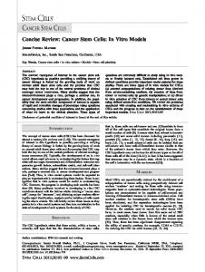
Figure 1. Terminologyusedthroughoutthis paper. (a) Fault length is the maximumdimensionof the fault plane perpendicularto the directionof slip; fault height is the dimensionparallel to the direction of slip. "Bell-shaped"and elliptical slip-length profiles are illustrated. (b) We useslip distribution to describethe displacementvariation on the fault plane, whereasdisplacementfield meansdeformation away from and includingthe fault plane. Most workersusethe term displacement to describeoffseton the fault plane, we will reservethe terms slip and dislocation to describeoffset on the fault plane; e.g., what workers often call displacement-length profiles, we call slip-lengthprofiles.
plastic yielding could occur at fault tips. However, some workersfind that a linear elasticmodel with varying frictional strength on the fault plane can producea "tapered"profile [B•irgmannet al., 1994]. We accountfor plastic yielding or differencesin strength at tips by using observed,rather than elliptical, slip-lengthprofiles as boundaryconditions. Given an observed,"bell-shaped"slip-length distribution, we show that
an elastic
dislocation
model
can be used to simulate
observedfault displacementfields. 2. Data
and Methods
The faultsstudiedare takenfrom a population of rift-related normalfaults from the Solite quarrynearEden, North Carolina.
The faults occurat high angles to finely layered lacustrine strata which preferentially break along bedding planes. Assumingthat beddingplanes were originally horizontal, we can attribute changes in bedding surface topography to faulting. The fine layering enables us to measurethe slip distributionaccuratelyalong fault-normalsaw-cuts. Becausethe faultsstudiedare only centimeterslong, we used a modifiedprofilometerto measurethe deformationfield along the exposed bedding planes of two faults. The original profilometer, designed and built by S. Brown and T. Koczynski,is describedby Brown and Scholz[1985]. andhas
sincebeenautomated. Theprecision of theprofilimeter is 10'6 m.
All samples were profiled in detail. For example, the bedding plane surfaceshown in Figure 2b was recordedwith The 10'2-10 2cmlongfaultsformedwithinlaminated siltstones 6100 data points (0.63 mm x 2.8 mm sampling interval). In of the Triassic Danville rift basin. The small faults follow the same scaling laws larger faults obey: powerlaw frequency- additionto profiling surfacedata, we set both faultsin epoxy length and linear slip-length distributions[Schlischeet al., and madeserial sections perpendicularto fault length in order 1996]. Other featuresthat they have in common with large- to measureslip distributions (Figure 2, white lines). We scale faults include bell-shaped slip profiles, pull-apart digitally scanned polished sections and measuredslip structures,horse-tail fan terminations, mineralized, multiple variationalong fault width (Figure 3). Sectiondata are accurate directionslickensidesalong fault planes, fault linkage, "relay to within a few pixels (0.2 mm) as determinedby several ramp" structures,footwall uplift, hangingwall subsidence,and replicated measurements.
highstrains(~10'2).Theirsmallsizeandsimilarityto largescale structuresmake them ideal for study. For more information about the fault population and the regional geology, see Schlischeet al. [1996]. From this population, we selectedtwo relatively isolated normal faults for detailedstudy:one 16 cm long (referredto as SA-16), the other 2 cm long (referredto as SA-02) (Figure 2).
3. Observations
3.1.
Displacement
Field
Detaileddescriptionsof large fault displacementfields are not available, but we have obtainedthis information for small
GUFFA AND SCHOLZ: UTILITY
OF ELASTIC MODELS
825
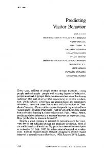
Figure 2. Map view of normalfaultsstudied.FW, footwall; HW, hangingwall. White lines showwhere samples havebeensectioned.The surfaces are profiledandplottedin Figures4 and5. (a) 2 cm long normal fault (SA-02) and (b) 16 cm long normalfault (SA-16).
faults. By measuringfaultedbeddingsurfaceswe provideclear representations of fault displacementfields (Figures4 and 5). Tapered slip-length profiles (Figures 4a and 5a) are indistinguishable from publishedslip-lengthprofilesof larger faults [e.g., Muraoka and Kamata, 1983; Barnett et al., 1987; Walsh and Watterson, 1989; Dawers et al., 1993; Peacock and Sanderson, 1994; Schlische et al., 1996].
However,thesesmall faults differ from large scalefaults in that their footwall uplift and hanging wall subsidenceare symmetrical about the fault plane (Figures 4b and 5b). (Footwall uplift and hangingwall subsidenceare consequences of flexure, not drag, but some workers use the term "reverse drag"becauseof the appearanceof deformedbeds.) However, observedlarge-scalenormal faults and earthquakerupturescan display as muchas 10 times greaterhanging wall subsidence
than footwall uplift [e.g., Stein andBarrientos,1985; Armijo et al., 1996]. The coseismicasymmetryis usuallyattributedto thethultdip andfree surfaceeffect. Overa longertimescale,as faults grow, sedimentloading of the hanging wall basin, erosionof the footwall, and isostaticcompensationchange the displacementfield (Figure 6a) [e.g., King et al., 1988; Stein et al., 1988; Contreraset al., 1997]. Some workers have attemptedto disentangle the elastic, viscous flow, erosional and depositional components of fault structureand growth [King et al., 1988; Stein et al., 1988; Ma and Kusznir, 1994; Armijo et al., 1996; Contreras et al., 1997]. Their studies suggestthat fault displacementfields become more, but not completely, symmetricalas isostatic compensationoccurs.
Our interpretation for small, buried faults is necessarily different.
In
our
small
faults
there
is
no
isostatic
..
..............
.
•
0
..............................
...,
....."
ß-".•.:'
•
:.•:":.• ....
..........
":•:'. :': ........ .7......::.....v .::;•; ...:-':•'.' • "' .:: ........ .' .....::-'•.4. .... •
,.........
•
.....
:.•:.•...•:.
..
}
2
3
4
S cm
...•..:. v..................:c:.,. :...: