The layer assignment, which is also called the Constrained Via. Minimization (CVM), assumes that the topologies of all nets and all interconnections are known.
Via Minimization with Associated Constraints in Three-Layer Routing Problem Sung-Chuan Fang, Kuo-En Chang*, and Wu-Shiung Feng Department of Electrical Engineering, National Taiwan University, Taipei, Taiwan, R.O.C. *Department of Information and Computer Education, National Taiwan Normal University, Taipei, Taiwan, R.O.C. Abstract -- Via minimization is the same as layer assignment problem in VLSI or PCB routing. It is to determine which layers can be used for routing the wire segments such that the number of vias can be minimized. In this paper, we present a heuristic algorithm to globally eliminate the vias in the three-layer channel routing. Some associated constraints, such as restricted terminals and adjacent limitation, will be addressed extensively. According to the results, the algorithm is faster and efficient to generate very good results.
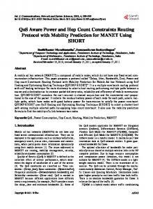
I. INTRODUCTION T h e routing problem is of importance in VLSI/LSI layout. In the most current technologies, three layers are available for routing. Some of three-layer routing algorithms [8-111 utilize the VHV or HVH mode. The assumption of both modes can efficiently avoid the possibilities of unacceptable short-crossing, i.e. the crossings of different nets on the same layer. It would, however, produce a large number of vias in the layout. From a technological point of view, the number of vias should be kept small. Hence, the via minimization has to be considered in the routing algorithms. The layer assignment, which is also called the Constrained Via Minimization (CVM), assumes that the topologies of all nets and all interconnections are known. That is to say, the topology of layout is fixed while the wire segments are to be assigned to the layers in order to eliminate the unnecessary vias. In this paper, we will use both terms interchangeably. The example of three-layer CVM problem is sketched in Fig. 1. Some of vias in the layout drawn in Fig. l(a) arereduced by the layerreassignment of all wire segments, and the final result with one via only is shown in Fig. I(b). This final result has the fixed topology of interconnections as shown in Fig. l(a). The algorithms proposed for CVM problem in the two-layer routing were presented by [1]-[7]. The two-layer CVM problem is not NP-complete when the junction degree is less than or equal to 3 and it can be solved by the polynomial time algorithm. With the advent of VLSI technology, three-layer routing becomes feasible [8]-[ 1I]. Therefore, CVM problem for three-layerrouting is needed to be solved. Chang and Du [12] first formulated the three-layer CVM problem and showed it is an NP-complete problem. A heuristic algorithm for the three-layer CVM problem were presented by them. Both local sense and global sense are considered in the algorithms to solve the three-layer CVM problem. An algorithm with local sense checks vias one by one to see if the via can be eliminated by reassigning new layers to the wire segments connected to this via. In the other words, the local sense algorithm is only to reassign layers of some wire segments in the given topology if vias can be eliminated and leave the layer assignments of the other wire segments to be unchanged when they are not helpful with via mini-
mization. For global sense, the given topology is assumed to be "layerless" routing, and the minimization of vias is done by assigning all wire segments in the routing to new layers so that vias can be produced as small as possible. As stated above, the local sense algorithm would be seriously influenced by the given assignment of each wire segment because it considers only the condition in the neighborhood of a via. It may also infect the layer reassignment of other wire segments. Due to this property, the algorithms with local sense are suitable to the problems with small size and these will become inefficient when the problem size is grown. In general case, the result from local sense algorithm is worse than the one with global sense. The heuristic algorithm presented by Chang and Du [12] was to minimize the vias with local sense. Hence, the algorithm is efficient to the routing examples with small problem size. Our first version of via minimization (See Ref. [ 151) eliminated vias in the layout by globally view and presented the better results. In the paper, we add special constraints on the via minimization. To solve CVM problem, generally, the terminals are allowed to be available for any layer, but in practical, there may be only some layer(s) allowed. In addition, vias connecting wire segments in any different layers are permitted. However, vias, are only allowed to connect wire segments in adjacent layers, will get more important in VLSI design. On these special constraint, we defined some styles for the via minimization as follows: (1) GO-THROUGH style: There is no constraint on both terminals and vias. (2) ADJACENT style: Vias are only allowed to connect wire segments in the successive layers, such as layer i and layer i+l. (3) lr-TERMINAL style: The terminals are restricted to only one layer. (or only one layer is available for terminals) (4)2r-TERMINAL style: The terminals are restricted to two special layers.
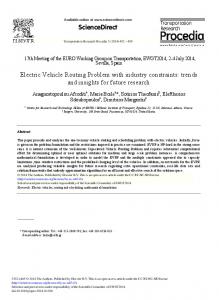
11. FOUNDATIONS AND GRAPHMODELOF VIA MINIMIZATION A crossing is an intersection where two wire segments of different nets are intersected each other. There are two types of crossing as shown in Fig. 2. A transient routing is an incomplete or "layerless" physical routing in which the topology of nets in routing has taken place, whereas the wire segments in the routing have not yet been assigned to layers. Fig. 3 is an example of transient routing. The transient routing can be represented as a graph called Segment-Crossing Graph (SCG) denoted as GS=(V& U Ec). The graph is consmcted as follows. Each vertex in Vsrepresents a wire
CH2868-8/90/0000-1632$1.000 1990 IEEE
segment in the transient routing. The edges in Gs is divided into two sets including the set of via-edges (denoted as Ev)and the set of cross-edges (denoted as Ec). If there is a via connected both wire segments, an edge in Ev will connect both corresponding vertices in SCG. An edge in Ec, which is connected two vertices in SCG, means two corresponding wire segments are crossing. We use dashed lines and solid lines for two different kinds of edges. For the transient routing of Fig. 3, its SCG is shown in Fig. 4.
1. input a layout and construct a segment-crossing graph Gs, and let all vertices in Gsbe inactive vertices; 2. REPEAT 3. select an inactive vertex U in Gs; 4. IF vertex U is 3C vertex THEN BACKTRACK@); ELSE assign vertex U to a color, a(u); 5. 6. calculate r(i) by r(i) = r(i) U a(u), for all i E A@). 7. calculate c(i) by c(i) = c(i) U a@), for all i E C(U). 8. UNTIL all vertices in Gsare active vertices.
For each vertex U E VS,we define a set of vertices, which are adjacent to U by the edges in Ev,to be an adjacent list of U, and the other set of vertices which are connected to U by the edges in Ec is defined as a clusrer of U. The adjacent list and the cluster of vertex U are denoted as A(u) and C(U),respectively.
Initially, all vertices in Gsare inactive vertices. One of them will be selected to be assigned a color. Because the result of the algorithm depends on the order of selecting the inactive vertices, we use a priority function to determine the sequence of the selected vertices. The priority function is estimated at each vertex in Gs.Step 3 selects an inactive vertex based on the nonincreasing order of priority of the vertices. Each inactive vertices will be classified in some kinds based on the Ic(u)l. Each inactive vertex is going to be one of OC, lC, 2C, and 3C kinds when there are three colors needed for the three-layer routing. The highest priority vertex is 3C vertex and lowest one is OC vertex. If some inactive vertices are the same kind, one with highest degree of constraints will be selected first from them. Initially, all vertices in Gsare OC vertices. However, if we want to obtain the ADJACENT style solution, then the wire segments will be classified into two categories including horizontal and vertical wire segments and the priority of horizontal wire segments is higher than the vertical wire segments.
Let each layer in three-layer routing be represented by one color. The layer assignment problem of the three-layer transient routing can be translated to 3-colorable problem of Gs. The layer assignment of wire segments in the transient routing is to assign each vertex in the 'colorless' graph Gs a color such that two vertices, which are connected by an edge in Ec, are painted by different colors, and such that two vertices, which are connected bv an edge in E". are painted by samecolor as possible. In theotherwords, acolorpainted on the vertex U is different from the colors assigned on the vertices in C(u) and is same with the colors assigned on the vertices in A(u) as possible. Initially, the three-layer transient routing is feasible, and the corresponding graph Gsis 3-colorable. Fig. 5 is acolorable SCG of graph shown in Fig. 4 and its corresponding layout is given in Fig. 6 with one via only.
In the case of 3C vertex, a(u) = I$,that is in contradiction to 3colorable assumption. In order to hold the 3-colorable requirement, the color reassignment of active vertices is needed during the color assignment of 3C vertex. The BACKTRACK procedure is to reassign some active vertices in C(u) to new colors so that the 3C vertex U can be assigned to alegal color. This approach of backtracking can refer to [151.
In. HEURISTIC ALGORITHM The 3CVM is shown to be NP-complete. Therefore, a heuristic algorithm is proposed in this section. Let us first consider the segment-crossing graph Gs = (Vs,Ev U Ec) and two sets of vertices associated with each vertex U E Vs. One is the adjacent list of U,and the other is cluster of U. The wire segments corresponding to the vertices in A(u) are contacted by vias to the wire segment associated with the vertex U. The wire segments corresponding to the vertices in C(U)are crossing with the wire segment associated with the vertex U. The colors assigned to the vertices in A(u) are the recommended colors of vertex U. If the vertex U is colored with one of the recommended colors, some vias contacting to the wire segment corresponding to U can be eliminated. The colors assigned to the vertices in C(u) are the constrained colors of vertex U. The constrained color indicates a color to which the vertex U can not be assigned for avoidance of violating the layout requirement. Therefore, the expected colors of vertex U to eliminate vias are the colors which belong to the recommended colors of vertex U but not the constrained colors of vertex U.
We have to decide the active color assigned to the vertex selected in Step 3. Let L = IO, 1 , 2 ) be a set of colors corresponding to the three layers used in the routing. The active color of vertex, a@), must be one in the set of L - c(u).'The best color is determined as follows. Let Irz(u)l be the number of color 2 in r(u) and z E L. To eliminate the maximum number of vias, the color assigned to an inactive vertex U will be a(u) satisfying the feasible condition that is defined below. a(u) = z, z E e(u) and Irz(u)l is maximum.
However, we have to meet constraint of color decision when we consider the ADJACENT stvle solution. For the ADJACENT style consideration, the colors assignment of horizontal wire segment are limited to be two colors 0 and 2 only, but the color assignment of vertical wire segments is free to assign any color.
A color that has been assigned to a vertex U is called active color of U denoted as a(u). The vertex U that has assigned a color is called active vertex, and it is called inactive vertex if it has not been assigned a color. Let r(u), c(u), and e(u) be the collections of recommended colors, constrained colors, and expected colors of vertex U, respectively. r(u), c(u), and e(u) can be expressed in the following formulas.
IV. EXTENSIONS In previous sections, we consider the 3CVM problem that has its major objective of minimizing the total number of vias. However, some constraints will also be addressed. For instance, there are two constraints considering in the 3CVM problem.
r(u)= (a(i) 11 I i < n a n d i E A@)). [ 11 Some nets are preassigned to a particular layer. [2] Terminals can be restricted to be available on only one or two of the three layers.
c(u) = (a(i) 11 S i S n andi E C(u)).
The preassignment of a net to a particular layer z means the vertices of Gsassociated with all wire segments in the corresponding net are set to be active with color z. This constraint can be completed by a preprocessor for preassignment of a net.
A vertex U is calledp-constrained vertex (or called pC vertex for simplicity) if Ic(u)l = p , where Ic(u)l is the number of distinct colors in c(u). On the consideration of above definitions, our proposed heuristic algorithm can be presented step by step and the details will be addressed later.
If terminals are available for one particular layer, each associated 1633
vertex of wire segment connected to the terminal can be appended by two dummy vertices and the dummy vertices are set to be active and painted by the suitable colors. For example, the terminals are restricted to be on the first layer, two dummy vertices with colors 1 and 2 force the associated vertex to be painted by color 0. It means the wire segment connected to the terminal is only located at first layer. For the case of terminals restricted on two particular layers, we only use a dummy vertex to force the wire segment connected to terminals to be at these two particular layers.
Florida, pp. 295-298, June 1980. [3] M. J. Ciesielski and E. Kinnen, "An optimum layer assignment for routing in IC's and PCB's," in Proc. 18th Design Automation conf., Nashville, Tennessee, pp. 733-737, June 1981. [4] R. Y. Pinter, "Optimal layer assignment for interconnect," J. VLSI and Computer Systems, vol. 1, no. 2, 1984, pp. 123-137. [5] K. C. Chang and H. C. Du, "Efficient algorithms for layer assignment problem," IEEE Trans. Computer-Aided Design, vol. CAD- 6 , no. 1, pp. 67-78, Jan. 1987. [6] X. M. Xiong and E. S. Kuh, "The constrained via minimization problem for PCB and VLSI design," in Proc. 25th Design Automation Conf., Anaheim, Califomia, pp. 573-578, 1988. [7] Y. S. Kuo, T. C. Chem and W. K. Shih, "Fast algorithm for optimal layer assignment," in Proc. 25th Design Automation Conf., Anaheim, Califomia, pp.554-559, 1988. [8] Y. K. Chen and M. L. Liu, "Three-layer channel routing," IEEE Trans. Computer-Aided Design, vol. CAD-3, no. 2 pp. 156-163, Apr. 1984. [9] V. Pitchumani and Q. Zhang, "A mixed HVH-VHV algorithm for three-layer channel routing," IEEE Trans. Computer-Aided Design, vol. CAD-6, no. 4, pp. 497-502, July 1987. [lo] S. E. Hambrusch, "Channel routing algorithm for overlap models," IEEE Trans. Computer-AidedDesign, vol. CAD-4, no. 1 , pp. 23-30, Jan. 1985. [ 111 F. P. Preparata and W. Lipski, "Optimal three-layer channel routing," IEEE Trans. Comput., vol. C-33, no. 5, pp. 427-437, May 1984. [ 121 K. C. Chang and H. C. Du, "Layer assignment problem for three-layer routing," IEEE Trans. Comput., vol. C-37, no. 5, pp. 625-632, May 1988. [ 131 M. R. Garey and D. S. Johnson, Computers and Intractability. San Francisco, CA: Freeman, 1979. [ 141D. N. Deutsch, "Adogleg channel router," in Proc. 20th Design Automation Conf., pp. 591-597, June 1983. [ 151 K. E. Chang, H. F. Jyu, and W. S. Feng, "Constrained via minimization for three-layer routing," COMPUTER-AIDEDDESIGN, vol. 21, no. 6, pp. 346-354, july/august 1989.
VII. RESULTSAND CONCLUSIONS The algorithm for threelayer via minimization was coded in c language and implemented on SUN 3/110C workstation. The algorithms are efficient and have been evaluated on some examples including examples 1, 3a, 3b, 3c, 4b, and 5 presented in [8] and Deutsch's difficult example [14]. There are four styles to be tested. Fig. 7-10 show the four styles of final layouts after some vias are eliminated for the Deutsch's difficult example presented in the paper PI. In this paper, we present a heuristic algorithm with global sense to the problem of three-layer via minimization. Some constraints are addressed in the algorithm. The constraints of restricted terminals and adjacent limitation result into four styles of solutions. From our experiments, the algorithm is faster and efficient to generate very good results.
REFERENCES [ 13 A Hashimoto and J. Steven, "Wire routing by optimizing channel assignment within large apertures," in Proc. 8th Design Automation Workshop, Santa Barbara, Califomia, pp. 155-169. June 1971.
[2] Y. Kajitani, "On via hole minimization of routing in a 2- layer board," in Proc. IEEE 1980 Int. Conf.Circuit Computers, Orlando,
This work was supported by National Science Council,Taipci,Taiwan, R.O.C., under the Con tract #NSC7g-@$@$-E002-46.
Fig. 1 (a) The orlglnal layout. (b) Final layoul
~.
,------------
-r-
(a)
(b)
Flg. 2 (a) Crossover of two wlre segments (b) Overlap of two wlre segments
1634
s9
s7
s8
OS'
V l
v3
SZ
vz
c4
e9
c7
c3
c8 s10 v7
Sll
V8
0 s3
s12
Fig. 4 Segment-crossing graph.
Pi -.
4
3
1 I
I
s7 I
. ~
:......... . ..... ..................}.................... ......... ...;
j
s5
s4
2
2
I
is12
1
................... ........___. .................._______. ....... ...................................
7
s8
S2
s6
_____..._________ I
s10
I
s9
Sll
1
3
4
1
Fig. 6 The physical routing.
Fig. 8 Final layout of Deutsch's difficult example (ADJACENT style). I ' , ~7 ~ , ~ , nlayout l of Dcutsch's difficult example (GO_TI