unmanned aircraft for aerial refueling, using the refueling boom system currently adopted by the US Air Force. A pose estimation system for satellite servicing is ...
2013 21st Mediterranean Conference on Control & Automation (MED) Platanias-Chania, Crete, Greece, June 25-28, 2013
Virtual Simulator for Testing a Vision based Pose Estimation System for Autonomous Capture of Satellites with Interface Rings∗ Andres F. Velasquez1 , Giacomo Marani2 , Thomas Evans3 , Marcello R. Napolitano4 , John A. Christian5 , Gianfranco Doretto6 Abstract— This paper describes the design and the performance of a virtual simulation environment to evaluate a machine vision based pose estimation system used for the general problem of satellite servicing. The vision system features a wide angle monocular camera to track the interface ring of a non-cooperative satellite using ellipse extraction. The effects of the camera parameters and of the relative camerasatellite position on the system accuracy are evaluated. Different parameters such as resolution, field of view angle, distortion, occlusions and errors in the intrinsic parameters are considered. The study reveals the importance of the availability of such a visual simulation environment for the purpose of mission planning.
I. I NTRODUCTION An important need in the space technical community is the development of capabilities for servicing existing orbital assets [1]. Current satellites will reach the end of their operational life when the fuel required for position and attitude control will be depleted, or when other components (e.g. batteries, reaction wheels, etc.) will wear out. Over the last two decades, NASA and other space agencies have shown an increased interest in on-orbit satellite servicing. This consists of sending a servicing vehicle to capture the dying satellite (target), and to perform refueling, replacement of faulty components, or other servicing tasks. Space missions such as those described in [2], [3] and [4] have successfully proven the technology required for rendezvous with cooperative satellites, i.e. satellites equipped with a system to assist a servicing spacecraft in the docking and servicing operations. Non-cooperative satellites do not have such devices; therefore, natural features have to be used for this purpose. Particularly, the use of the interface ring - used to attach the satellite to the launch vehicle - has been proposed for capturing the satellite [5],[6],[7]. Current efforts are * Research supported by NASA Goddard Space Flight Center. 1 A. F. Velasquez is with West Virginia University, Morgantown, WV, USA avelasq2 at mix.wvu.edu 2 G. Marani is with the WVU Research Corporation, West Virginia University, Morgantown, WV, USA marani at ieee.org 3 T. Evans is with the College of Engineering and Mineral Resources, West Virginia University, Morgantown, WV, USA thomas.evans at
mail.wvu.edu 4 M. R. Napolitano is with the Department of Mechanical and Aerospace Engineering, West Virginia University, Morgantown, WV, USA
marcello.napolitano at mail.wvu.edu 5 J. A. Christian is with the Department of Mechanical and Aerospace Engineering, West Virginia University, Morgantown, WV, USA
john.christian at mail.wvu.edu 6 G. Doretto is with the Lane Department of Computer Science and Electrical Engineering, West Virginia University, Morgantown, WV, USA
gianfranco.doretto at mail.wvu.edu 978-1-4799-0997-1/13/$31.00 ©2013 IEEE
testing servicing operation for non-cooperative satellites such as the NASA’s RRM (Robotic Refueling Mission) [5] and the prospected DEOS (Deutsche Orbitale Servicing Mission) [8] from DLR. When the servicing satellite vessel is between 10m and 2m from the target, a typical operation [2], [3], [9] is to use a robotic arm to capture the satellite. This activity has to be performed autonomously due to the communication delays between on-orbit systems and ground. Therefore, the robot controller requires a real-time pose estimation system to obtain the pose (position and orientation) of the satellite w.r.t the vessel. For non-cooperative satellites, machine vision-based pose estimation systems that use the satellite natural features such as the interface ring have been proposed [2], [7], [10], [11]. The expectations are that the system must provide the satellite’s relative position and attitude with an adequate accuracy and sampling rate, and must be robust to occlusions and lighting conditions. The required pose accuracy is usually a function of the relative position, being more stringent at closer positions. In this paper, a virtual simulator is used to evaluate the design and the performance of a machine vision-based pose estimation system which uses a monocular camera mounted on the end-effector of a robotic manipulator (hand-eye). The system uses the interface ring as the feature to track and grasp, and an ellipse extraction system is used to detect the ring. The evaluation consists of finding the system accuracy (defined as the pose estimation error) and the effects of the system parameters on the system accuracy. Additionally, a calibration procedure is performed and its effects on the accuracy are evaluated. The real pose estimation system was developed and tested at the West Virginia Robotic Technology Center (WVRTC) facility [12]. This virtual simulation study was conducted in order to understand the effects of the system parameters on its performance. II. R ELATED W ORK Virtual simulations are useful in the evaluation of visionbased pose estimation systems and have become a common practice, in addition to experimental tests, since they can provide the true pose between the camera and the target object. Reference [13] describes the design of a virtual environment to test a pose estimation system based on corner extraction to estimate the pose between a tanker and an unmanned aircraft for aerial refueling, using the refueling boom system currently adopted by the US Air Force. A pose estimation system for satellite servicing is evaluated in [6] using a virtual simulation. The system features a
1597
monocular camera with a 55deg field of view (FOV) to track the interface ring and an edge of the satellite. The results show pose estimation errors of less than 5cm and 2deg when the distance target/service vehicle is approximately 5m. The system described in [10] implements the moving-edge algorithm in a model-based pose estimation system to track the linear edges of a satellite. It uses a monocular camera and it is intended for satellite servicing. Virtual and real images are used to evaluate the system. The above described prior efforts use virtual simulations to study the system under ideal conditions. In real life, in addition to the noise in the image acquisition and light conditions, there are other sources of errors that affect the pose estimation, such as errors in the estimation of the intrinsic parameters of the camera, lens distortions, as well as occlusions. The main contribution of this paper is to evaluate the effects of those parameters (excluding image noise, blur, and light conditions) in the pose estimation, which are not considered in the above mentioned references. Additionally, the intrinsic system non-linearities due to lens distortions, image sampling, quantization, and saturation affect the pose estimation error as the relative camera-target position changes. These important effects have also been considered in this study. The system is evaluated at close proximity to the target (from 2m to capture), where occlusions or partial view of the target are likely to occur. The efforts described above only show results up to 5m from the target. III. P OSE E STIMATION S YSTEM The pose estimation system considered in this effort features a monocular camera with a wide-angle lens having a horizontal FOV of 105deg, low radial distortion (3% barrel), and a maximum resolution of 1280x960 pixels. The camera is mounted on the end-effector of the robotic manipulator (which has the capture tool), located as shown in Fig. 1, to allow the system continuous tracking of the interface ring. Also, this configuration maximizes the view of the ring at the grasping position. As shown in the flowchart of Fig. 2, the algorithm has two main components: a machine vision system and an extended Kalman filter (EKF). The following sections explain each component with more details.
Fig. 1: Grasping position and camera location (top view).
A. Machine Vision System The machine vision system provides the Cartesian position of the center of the ring with respect to the camera and the normal vector to the ring plane. The blocks of this system are image processing, ellipse extraction, ellipse detection,
Fig. 2: Flowchart of the pose estimation algorithm.
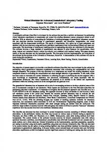
and pose estimation. The flowchart of Fig. 2 shows their connections, and corresponding inputs and outputs. The following is a description of the main blocks. Image processing. Once the image has been acquired and rectified, Canny edge detection is performed over the blue channel of the image.1 to provide a binary edge map. Fig. 4(a) shows such map representing the edges detected from an image of the simulator. Ellipse extraction. This block uses the ellipse extraction algorithm described in [14]. It takes the binary edge map, extracts the ellipses in the image, and provides their geometric parameters. Those are the coordinates of the ellipse center (xc, yc), the length of the major and minor semi-axes (a, b), and the angle of the major axis with respect to the horizontal coordinate of the image (ang). Fig. 4(b) and (c) show such ellipses in green, extracted from the images generated by the simulator. Ellipse Detection. The set of extracted ellipses may contain the ellipse corresponding to the ring, as well as ellipses corresponding to other objects with elliptical shapes, or even their reflections onto the MLI. The ellipse detection system selects the ellipse corresponding to the ring from the set of extracted ellipses. Such detected ellipse is obtained by comparing the geometric parameters of the extracted ellipses against a ref erence ellipse obtained by projecting the ring onto the image plane using the current pose prediction, provided by the EKF. The detected ellipse is computed as the one that minimizes the cost function, Ji = (aref − ai )2 + (bref − bi )2 + (xcref − xci )2 + (ycref − yci )2 , where aref , bref , xcref , ycref are the geometric parameters of the reference ellipse, and ai , bi , xi , yi are the geometric parameters of an extracted ellipse. Fig. 4(b) and (c) show the detected ellipse in red. Pose Calculation. Using the geometric parameters of the detected ellipse, the coefficients A, B, C, D, E and F , of the quadratic equation for an ellipse, A x2 +B x y+C y 2 +D x+ 1 The blue channel provides a better contrast of the ring against the background, which is covered with Multi-Layer Insulation (MLI), a highly reflective material used to help controlling the satellite temperature.
1598
E y + F = 0, are obtained analytically. The normal vector and the 3D position of the ring can be obtained analytically as functions of the coefficients, as described in [15]. This method provides two possible solutions for the pose of the circle, and additional information is required to pick the right one. In this work such ambiguity is resolved by choosing the solution that is closer to the EKF prediction. When the circle is orthogonal to the camera optical axis, the two solutions are equal. Initialization. When the system is initialized, a conveniently predefined previous-time pose is assumed in order to generate the reference ellipse. In particular, the initial configuration assumes the camera to be at 2m from the ring, with the end-effector axis orthogonal to the ring plane. Typically, the ring is the largest feature, easily detectable, after a disambiguation between the inner and outer ring diameter. More details about the pose estimation can be found in [12].
Fig. 3: Virtual simulator. Top left: camera view. Top rigth: external orthogonal view. Bottom: Global view.
B. Kalman Filter The EKF is used to reduce the noise in the measurements given by the pose estimation system. As mentioned above, the EKF predicts the next-time pose that is required to generate the reference ellipse. The EKF dynamics assume a constant velocity model. The pose is represented by a quaternion and a 3D position vector of the target with respect to the camera. Only 5DOF can be estimated, since the system is invariant to rotations around the ring axis.
(a)
(b)
(c)
(d)
IV. V IRTUAL S IMULATOR To evaluate the pose estimation under controlled conditions, a virtual simulator was developed to emulate the actual system at the WVRTC facility, as well as a typical non-cooperative satellite. The simulator generates a virtual environment containing 3D-models of the satellite and the end-effector (see Fig. 3). It creates a virtual view based on the same intrinsic parameters of the camera of the real system (Fig. 4), and also allows simulating the radial distortion. The satellite used in the simulation has an interface ring with a diameter of 1.2m, a thickness of 40mm, and a depth of 84mm. Relative motion between the satellite and the end-effector can be generated (e.g., translations and rotations along specific axes, or following a specified path, or maintaining a fixed relative position). In addition to 3Dmodels, the system can generate a binary image of a circle (Fig. 4d), which is used to evaluate the system in absence of noise. The latter may be generated by additional ring edges, arising from the inner radius of the ring, by the back face of the ring, or by other circular features present in the target, such as thrusters and heat shields. The simulator and the pose estimation algorithm are implemented in C++ using OpenGL. The frames are converted to OpenCV images and provided to the pose estimation system. A data logger system saves the estimated pose and the ground-truth pose from the virtual simulator. The system is running on a Linux desktop with two quad-core Xeon processors and 4GB of Ram. Fig. 3 shows the simulator environment.
Fig. 4: Image processing. (a) edge map (b) camera view from the NEAR nominal position and extracted ellipses. (c) camera view from the FAR nominal position and extracted ellipses. (d) circle model image generated by the simulator.
V. S YSTEM PARAMETERS The estimated pose of the ring is function of the camera parameters (cx , cy , fx , fy ) and the geometric parameters of the detected ellipse (ad , bd , xcd , ycd , angd ). In a real system, the intrinsic parameters are obtained through a camera calibration process, which also compensates for the radial distortion [16]. This means that the values for cx , cy , fx and fy are only estimates, and therefore are corrupted by noise. Those calibration errors, which add up to other smaller image distortions not explicitly modeled, directly affect the accuracy with which the pose is estimated. Image resolution can be another nuisance factor influencing the system accuracy. In particular, a lower image resolution leads to a more pronounced pixelization of the ellipse edges, which, in turn, affects the estimation of the ellipse geometry and the pose. Moreover, the pixelization can be different, depending on the relative position between camera and target, suggesting the need to investigate how it
1599
affects the final pose estimation. Besides the effects of the camera intrinsic parameters and of the relative pose on the system accuracy, this paper also studies the effects of the radial distortion. This is done by generating distorted images (typical of wide angle lenses), according to the model: (xu , yu ) = (1+K (x2d +yd2 ) (xd , yd ), where xd , yd are the pixel coordinates in the distorted image (w.r.t. the center of the image), while xu , yu are the coordinates of the corresponding pixel in the undistorted image and K is the radial distortion coefficient. The system accuracy is defined as the translation error ~ truth − X ~ est | and the rotation error T ranserror = |X ~ ~ est |), where X ~ est and N ~ est Roterror = asin(|Ntruth × N are the estimated position and normal vectors of the ring, ~ truth and N ~ truth are the corresponding actual vectors and X (ground-truth). A pose estimation system can be further calibrated using another system with higher accuracy. This calibration is performed to remove some of the bias errors in the system. During the calibration the more accurate system is used to find a transformation matrix, Tcal , such that Pc = Tcal Pm , where Pm is a measured position or normal vector, and Pc is the corresponding calibrated vector. In this study, the calibration transformation matrix is found at the grasping position, where more accuracy is needed, due to the target proximity. When the calibration is applied during the system regular operation, all the measurements of the pose estimation are multiplied by the transformation matrix. The effects of this calibration on the overall pose estimation are also studied by finding and applying the calibration transformation matrix in a system with errors in the camera intrinsic parameters. The following section describes the virtual tests performed for the system evaluation. VI. T ESTING S ETUP The tests are classified in three types, i.e., Parameters, Position, and Calibration. During each test the estimated pose and the actual pose are recorded. The P arameters tests are performed using a nominal set of parameters (nominal configuration, see Table I) at two locations: f ar and near (see Table II). The far location represents the starting point of the capture phase, where the camera is at about 2m from the target. The near location represents the grasping or capture position as shown in Fig. 1. The camera views at these positions are presented in Fig. 4(b) (near) and in Fig. 4(c) (far). For each location each system parameter is modified one at a time, w.r.t. the nominal configuration. Two different values, low and high, are used for each parameter. The intrinsic parameters are modified by adding a small error to the nominal values. The error for fx is denoted as ∆fx , and similar meaning is given to ∆fy , ∆cx and ∆cy , with the further assumption that ∆fx = ∆fy . The error is simulated by generating the image using nominal values. However, the pose estimation system uses the values with errors, i.e., fx + ∆fx , etc. The parameters considered for this test are: ∆fx , ∆fy , ∆cx , ∆cy , f ov angle, image resolution, image radial distortion, and percentage of
TABLE I: Camera Testing Conditions
Nominal value
fx , fy 240
Inaccurate cam.
241
Parameter
vfov [deg] 320 240 90
640x480
321 241
640x480
cx
cy
res.
90
% ring 100
K 0.0 4.5E-7 (3%)
100
TABLE II: Nominal Locations Cond. Far Near
φ θ ψ x [m] [deg] [deg] [deg] -10 90 -10 -2.0 -10 90 -10 -0.7
y [m]
z [m]
-0.4 -0.4
0.0 0.0
the ring on view. The corresponding values are presented in Table III. They are chosen to represent prototypical cases found in practical applications, and to match the camera parameters used in the real system. The P osition tests are performed using the two nominal locations previously defined (far and near). During the test each of the pose variables is modified, one at a time w.r.t. the nominal locations, by ∆φ, ∆θ, ∆ψ (variations in the Euler angles representing the target orientation), and ∆x, ∆y, ∆z (variations in the translation along the target axes). Two values (low and high) are used for each variable, as shown in Table IV. These variations represent motion defined in the target frame, meaning that the camera does not move. In Calibration tests, an inaccurate camera configuration is defined (see Table I), which is a camera with errors in the intrinsic parameters and radial distortion. Tests at two positions (far and near) are performed. At each position, the orientation of the target w.r.t the camera is modified. The target rotation angle and the corresponding angle between the camera optical axis and the ring normal are presented in Table V. Finally, an approaching motion is simulated, where the camera moves from 2m away from the target up to the grasping position. All tests are performed using the binary circle image. Calibration tests are also performed using the 3D-model image (blue channel). VII. T ESTING R ESULTS For each of the tests described in the previous section the average translation and rotation errors and their standard de-
1600
TABLE III: Values of the Parameters Used for Testing Modified Parameter
∆fx , ∆cx ∆cy ∆fy
vfov
res.
Low Value
-1
1
1
75deg
320x240
High Value
1
2
2
105 deg
1280 x 960
% ring
K 4.5E-7 (3%) 8.6E-7 (5%)
50 70
TABLE IV: Values of the Pose Variables Used for Testing Modified var Low value High value
∆φ [deg] -10 10
∆θ ∆ψ [deg] [deg] -10 -10 10 10
∆x [m] -0.1 0.1
∆y [m] -0.1 0.1
∆z [m] - 0.1 0.1
TABLE V: Testing Conditions for Calibration Condition ID Target Rotation ∆ψ [deg] Equivalent Angle Camera/target [deg]
B. Effect of the Relative Position
C1 -30
C2 -15
C3 0
C4 15
C5 30
35
25
20
25
35
viations are calculated. All the results are computed directly from the vision system, not the EKF. Reference [12] shows results from experiments with real data and with different lighting conditions. A. Effect of the Parameters Fig. 6 shows the average pose error and its standard deviation. The accuracy of the nominal configuration is presented in the first column of each plot. Comparing the modified configuration w.r.t the nominal configuration reveals that the values used for the resolution and the fov angle have relatively low impact on the system accuracy. Larger resolution tends to improve the accuracy, although the frame rate processing decreases. With a resolution of 640x480 pixels the system runs at 10-15fps (frames per second), while at 1280x960 pixels the system runs at 5-7fps. Lower f ov angles also tend to increase the accuracy, since the objects appear bigger in the image. The values used for the ring percentage and errors in the intrinsic parameters tend to have a moderate impact on the system accuracy. As expected, larger errors in the intrinsic parameters tend to decrease the accuracy. Larger portions of the ring improve the accuracy, and significantly decrease the measurements noise (standard deviation). Radial distortion has a larger impact especially at the near position, where the ring takes a large portion of the image, away from the center, where distortions are larger. The accuracy tends to be higher at the near location, where the standard deviation of the measurements is also smaller. These are general trends and since the system is highly nonlinear, the behavior may change also due to the specific camera-target relative position, or if multiple parameters are modified or corrupted by noise, and not just one at a time, as described above.
Fig. 5: Rotation and translation error variation w.r.t the system parameters. Values of the parameters are presented in Table III, where Ef=∆fx = ∆fy , Ex=∆cx and Ey=∆cy .
Fig. 7 shows the pose errors for the position tests. The accuracy at the nominal position is presented in the first column of each plot. It can be seen that there are small error variations w.r.t the nominal position, although most of them are of the order of one standard deviation, which is suggesting that the system is robust against position variations. One special case is the variation of ψ at the far position. Here the ring is almost in parallel position with respect to the camera image plane, and the pose estimation might face difficulties in disambiguating between the two, similar, admissible solutions. It is important to note that the variations in the position variables presented in Table IV are relatively small (0.1m and 10deg.). Bigger variations in the position will generate greater accuracy variations, as it can be seen when comparing the results of the far location against the near one, where changes in the accuracy of more than one order of magnitude can be observed.
Fig. 6: Rotation and translation error variation w.r.t the relative position between target and camera. Coordinates modified according to Table IV. C. Effect of the Calibration Fig. 8 shows the pose errors for the calibration test using the binary images, and Fig. 9 using the 3D-model. Each figure shows results for the accuracy of the system (using the inaccurate camera) before and after the calibration presented above, denoted as uncal. and cal. respectively. It can be seen that the calibration improved the accuracy, especially at the near location. By comparing the two figures it can be seen that when using the 3D-model image the system accuracy is lower, and its standard deviation is higher. This trend is due to the noise introduced by the additional features in the images. However, there is no clear trend of the accuracy w.r.t the relative orientation between camera and target. The accuracy after calibration is less than 8mm for translation and less than 1deg for rotations at the grasping position when using an image of 640x480pixels. which is acceptable for satellite capture procedures [12]. Fig. 10 shows the results after calibration for the approach that uses the 3D-model images. It can be noticed how the noise is larger when the system is farther away from the target. At this distance the system is unable to distinguish
1601
between the inner and outer diameter of the ring. Finally, the system performed well even with the occlusion created by the gripper and the heat shield (see Fig. 4b).
Fig. 9: Aproaching motion pose error estimation with calibrated system.
Fig. 7: Effects of the calibration (circle model). The Angle values are presented in Table V.
Fig. 8: Effects of the calibration (3D model). The Angle values are presented in Table V. VIII. C ONCLUSIONS The virtual simulation test suggests that the system accuracy is suitable for the design tasks of approaching and capturing a satellite using the interface ring as a reference feature. The system is robust w.r.t relative camera-target positions, and errors in the camera parameters, given that it maintains a consistent and satisfactory accuracy for a large range of such parameter configurations. A higher sensitivity is noted with respect to radial distortion, which is recommended to be kept as low as possible. The calibration process improves the accuracy and should be performed in a real system. R EFERENCES [1] B. J. Naasz and M. C. Moreau, ”Autonomous RPOD Challenges for the Coming Decade,” in AAS Guidance & Control Conference, Breckenridge, CO, 2012. [2] N. Inaba and M. Oda, ”Autonomous satellite capture by a space robot: world first on-orbit experiment on a Japanese robot satellite ETS-VII,” in Proceedings of the 2000 IEEE International Conference on Robotics and Automation, San Francisco, CA, 2000.
[3] A. Ogilvie, J. Allport, M. Hannah and J. Lymer, ”Autonomous Satellite Servicing Using the Orbital Express Demonstration Manipulator System,” in i-SAIRAS: International Symposium on Artificial Intelligence, Robotics and Automation in Space, Hollywood, 2008. [4] J. Christian, H. Hinkel, C. D’Souza, S. Maguire and M. Patangan, ”The Sensor Test for Orion RelNav Risk Mitigation (STORRM) Development Test Objective,” in AIAA Guidance, Navigaiton, and Control Conference, Portland, OR, 2011. [5] Goddard Space Flight Center, ”On-Orbit Satellite Servicing Study Project Report. National,” National Aeronautics and Space Administration, 2010. [6] X. Du, B. Liang, W. Xu, X. Wang and J. Yu, ”Pose Measurement of a GEO Satellite Based on Natural Features,” in International Conference on Virtual Reality and Visualization, Qinhuangdao, Heibei, China, 2012. [7] N. Inaba, T. Nishimaki, M. Asano and M. Oda, ”Rescuing a Stranded Satellite in Space - Experimental Study of Satellite Captures Using a Space Manipulator,” in Proceedings of the 2003 IEEE/RSJ Intl. Conference on Intelligent Robots and Systems, Las Vegas, Nevada, 2003. [8] F. Sellmaier, T. Boge, J. Spurmann, S. Gully, T. Rupp and F. Huber, ”On-Orbit Servicing Missions: Challenges and Solutions for Spacecraft Operations,” in SpaceOps 2010 Conference, Huntsville, Alabama, USA, 2010. [9] G. Rouleau, I. Rekleitis, R. L’Archeveque, E. Martin, K. Parsa and E. Dupuis, ”Autonomous Capture of a Tumbling Satellite,” Journal of Field Robotics, vol. 24, no. 4, p. 275296, 2007. [10] A. Petit, E. Marchand and K. Kanani, ”Vision-based Space Autonomous Rendezvous : A Case Study,” in International Conference on Intelligent Robots and Systems, 2011. [11] X. D. B. L. and Y. T. , ”Pose Determination of Large Non-Cooperative Satellite in Close Range Using Coordinated Cameras,” in International Conference on Mechatronics and Automation, 2009. [12] A. F. Velasquez, J. Luckett, M. R. Napolitano, G. Marani, T. Evans and M. L. Fravolini, ”Experimental Evaluation of a Machine Vision Based Pose Estimation System for Autonomous Capture of Satellites with Interface Rings,” in AIAA Guidance, Navigation, and Control Conference, Boston, Massachusetts, 2013. [13] G. Campa, M. Napolitano and L. F. Mario, ”Simulation Environment for Machine Vision Based Aerial Refueling for UAVs,” IEEE Transactions on Aerospace and Electronic Systems, vol. 45, no. 1, 2009. [14] L. Libuda, I. Grothues and K.-F. Kraiss, ”Ellipse Detection in Digital Image Data Using Geometric Features,” in Advances in Computer Graphics and Computer Vision, Springer, 2007. [15] Y. C. Shiu and S. Ahmad, ”3D Location of Circular and Spherical Features by Monocular Model-Based Vision,” in IEEE International Conference on Systems, Man and Cybernetics., Cambridge, MA , 1989. [16] Z. Zhang, ”A Flexible New Technique for Camera Calibration,” IEEE Transactions on Pattern Analysis and Machine Intelligence, vol. 22, no. 11, p. 13301334, 2000. [17] A. Cropp, P. Palmer, P. McLauchlan and C. Underwood, ”Estimating pose of known target satellite,” IEEE Electronics Letters , vol. 36, no. 15, pp. 1331 - 1332 , 2000.
1602