VirtualMesh: An Emulation Framework for Wireless Mesh Networks in OMNeT++ Thomas Staub
Reto Gantenbein
Torsten Braun
Institute of Computer Science and Applied Mathematics Neubrückstrasse 10 3012 Bern, Switzerland
Institute of Computer Science and Applied Mathematics Neubrückstrasse 10 3012 Bern, Switzerland
Institute of Computer Science and Applied Mathematics Neubrückstrasse 10 3012 Bern, Switzerland
[email protected]
[email protected]
ABSTRACT Wireless Mesh Networks (WMN) have proven to be a key technology for increased network coverage of Internet infrastructures. The development process for new protocols and architectures in the area of WMN is typically split into evaluation by network simulation and testing of a prototype in a test-bed. Testing a prototype in a real test-bed is time-consuming and expensive. Irrepressible external interferences can occur which makes debugging difficult. Moreover, the test-bed usually supports only a limited number of test topologies. Finally, mobility tests are impractical. Therefore, we propose VirtualMesh as a new testing architecture which can be used before going to a real test-bed. It provides instruments to test the real communication software including the network stack inside a controlled environment. VirtualMesh is implemented by capturing real traffic through a virtual interface at the mesh nodes. The traffic is then redirected to the network simulator OMNeT++. In our experiments, VirtualMesh has proven to be scalable and introduces moderate delays. Therefore, it is suitable for predeployment testing of communication software for WMNs.
Categories and Subject Descriptors I.6.8 [Types of Simulation]: Combined—network emulation
General Terms DESIGN, EXPERIMENTATION
Keywords wireless emulation, OMNeT++, integration of real nodes in simulated environment, pre-deployment testing
1.
INTRODUCTION
Wireless Mesh Networks (WMN) have become one of the key technologies for providing increased network coverage
Permission to make digital or hard copies of all or part of this work for personal or classroom use is granted without fee provided that copies are not made or distributed for profit or commercial advantage and that copies bear this notice and the full citation on the first page. To copy otherwise, to republish, to post on servers or to redistribute to lists, requires prior specific permission and/or a fee. OMNeT++ 2009, Rome, Italy. Copyright 2009 ICST, ISBN 978-963-9799-45-5.
[email protected]
of Internet infrastructures. The simple cost-efficient deployment with self-configuration facilities makes them a valuable alternative to wired networks to increase the network coverage [1]. Therefore, WMNs are in the focus of current research. Several research and city WMNs already exist [3, 5, 9] and WMNs are evolving from pure research networks to carrier-grade communication infrastructures, which require extensive pre-deployment testing. The development process in WMNs is typically split into evaluations by simulations and testing a real prototype in a test-bed. First, the protocols and architectures are implemented and evaluated in a network simulator. Afterwards, a prototype is implemented on the target platform such as Linux and tested inside a test-bed before deployment in the real network. Simulation provides most flexibility in testing. Different and large scale experiments as well as experiments with mobility of devices and users are possible. It provides the best way for testing and debugging the functionality of the approaches. But unfortunately, simulation models cannot cover all influences of the operating system, the network stack, the hardware, and the physical environment due to complexity constraints. Therefore, the transition from the simulation models to the deployable solution remains challenging. Testing the prototype in a test-bed during the implementation process is time-consuming, costly, and very limited. Due to economical reasons, the scale of the testbeds is limited and they are often not deployed in isolated environments, which limits reproducibility. Interferences with existing network are possible and irrepressible, which makes debugging of new protocols very challenging. Furthermore, the number of test topologies is limited and mobility tests are impracticable. Moreover, WMNs provide an enhanced testing challenge compared to simple wireless access networks. They support mobile users and high-throughput applications. Their architecture contains self-configuring and self-healing mechanisms, which have to be included in the tests. The cross-layer interactions have to be tested in a controlled environment without any irrepressible influences. Moreover, the tests have to cover time and delay aspects of the real network stack. All these tests cannot be fully done in simulations, but also in a test-bed they are difficult to be performed. We therefore propose to emulate the physical medium to gain more control in the development process. The authors of [7] validated the wireless model in the network simulator ns-2 by comparing measurements of a real network setup with an emulated and simulated network. They concluded that with a proper parametrization the sim-
Application
Transport (TCP, UPD, ...)
Internet (ARP, IP and ICMP)
MAC
Real or Virtualized Nodes Model
ulation model can approximate the real network, but some aspects like delays introduced by the hardware and the operating system cannot be considered in the simulation. Therefore, their emulated network provides results that match the real measurement more accurately than the simulation. The approach presented in [6] tries to integrate the behavior of the real network stack and the operating system into the testing process by using virtualized hosts connected through an emulation framework. The virtual hosts are running a L4 microkernel on top of a real-time kernel. To integrate the wireless network behavior, the hosts are connected by the 802.11b network emulator MobiEmu [16]. Although the authors praised the low hardware requirements of their approach, they did not publish any results about the accuracy of their setup. JiST/MobNet [10] provides a comprehensible Java framework for simulation, emulation, and real world testing of a wireless ad-hoc network. It allows to run the same tests independently of platform and abstraction level. MobNet is a wireless extension on top of the Java in Simulation Time (JiST) simulator. The drawback of this approach is that most communication software and network protocol stacks are not written Java and therefore afterwards a further transition to an embedded system may be necessary. Another approach for testing real implementations in a very flexible network is provided by the ORBIT testbed [11]. It provides a configurable indoor radio grid for controlled experimentation and an outdoor wireless network for testing under real-world conditions. The indoor radio grid offers a controlled environment as an isolated network, in which background interferences can be injected. Although the 20 x 20 grid of nodes offers a large variety of different topologies, it can be too restricted and mobility tests are even more limited. Furthermore, the scarce ORBIT resources may be not available for all experiments. UMIC-Mesh [17] is a hybrid WMN testbed. Besides a testbed with real wireless mesh nodes, UMIC-Mesh provides virtual nodes by using XEN virtualization. The virtual nodes are interconnected by a combination of the advanced networking features of the Linux kernel. This includes packet filtering for controlling the communication between the nodes. The virtual network is only intended for software development and functionality validation. Therefore, the behavior of the wireless medium is not modelled in this approach. In order to cope with the problem of a simulator overload during network emulation, the authors of [15] introduce the concept of synchronized network emulation. They replace real hosts with virtualized hosts using XEN. A central synchronizer component then controls the time flow of the virtual hosts by an adapted scheduler for XEN. It keeps them synchronized with the network simulator OMNeT++ [14]. The integration of real network stacks inside a network simulator provide another mechanism for testing complex protocol behavior. OppBSD [4] integrates the TCP/IP stack of FreeBSD in the network simulator OMNeT++. The project Network Simulation Cradle [8] provides support for using the real network stacks of Linux, FreeBSD, and OpenBSD with the network simulator ns-2. Our contribution is an emulation framework for WMNs for the network simulator OMNeT++. Our VirtualMesh framework offers enhanced evaluation of communication software written for real and virtualized nodes over an OMNeT++
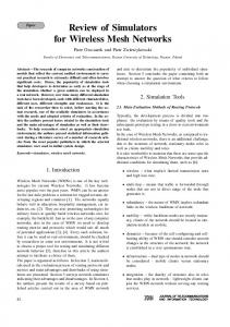
Figure 1: Subdivision of the network stack to the real / virtualized nodes and the simulation model.
simulation model. Communication software can be tested without any adaptations over an emulated network in OMNeT++. VirtualMesh uses real mesh nodes with a real network stack. It intercepts the wireless traffic before transmitting it over the air and forwards it to a simulation model. This simulation model offers a vast flexibility in topologies and mobility tests. In addition, the scale of the test scenarios can be increased by host virtualization [6]. The remainder of this paper is structured as follows. Section 2 presents the general architecture of VirtualMesh. In Section 2.1, the packet interception and forwarding is described. Section 2.2 shows the simulation model and the feeding of real traffic to the simulation. The individual procedures used in VirtualMesh are illustrated in Section 2.3. We provide an evaluation of VirtualMesh in Section 3. Finally, we presents our conclusions in Section 4.
2. VIRTUALMESH VirtualMesh combines the advantages of real world tests performed on embedded Linux systems with the flexibility and the controlled environment of a network simulator. The main advantages are: the real communication software is used, the real network stack is tested, background traffic/interferences can be controlled, and different mobility tests can be easily performed. The real implementation of the communication software can be tested. Accordingly, the behavior of the Linux network stack is embedded in a controlled testing environment. There are no irrepressible influences on the experiments such as interferences from neighboring networks and power lines, steel structures of buildings, or changing weather conditions. In addition, the underlying simulated network enables large scale experiments. It supports changing topologies and different mobility scenarios. This makes automated testing of the real communication software with a high variety of scenarios possible. The main concept of VirtualMesh is to intercept and redirect the real traffic at the nodes to a simulation model which then handles network access and the behavior of the physical medium. The network stack is therefore split into two parts as shown in Figure 1. The application, transport and Internet layer are handled by the real / virtualized node. At the MAC layer the traffic is captured by a virtual network interface and then redirected to the simulation model. The simulation model calculates the network response according to the virtual network topology, the propagation model, the background interferences, and the current position of the nodes. Only the MAC layer and the physical medium are
Node with physical interface
wireless extensions
network interface driver
hardware device
Linux Network Stack
network interface
wireless tools
wireless tools
Linux Network Stack
net-tools, ip-route2
App net-tools, ip-route2
App
Node with virtual interface
vifd
driver (tun) PacketModeller
simulated hardware device (WlanNIC)
(a)
(b)
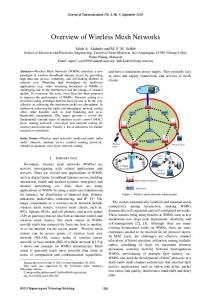
Figure 3: Node with Linux network stack and (a) a real network interface or (b) our virtual network interface (PacketModeller ) communicating with the OMNeT++ simulation model..
simulated. All the other layers remain unchanged and work just as in a real test-bed of embedded Linux nodes. The general architecture of VirtualMesh is shown in Figure 2. It consists of one or several computers hosting the simulation model and real or virtualized mesh nodes. The nodes and the model are interconnected by a dedicated IEEE 802.3 Ethernet service network. The wireless interfaces of the nodes are replaced by virtual interfaces which communicate over the service network to the simulation model. Besides real nodes, the architecture supports virtualized hosts. Host virtualization is performed by XEN [2]. However, other virtualization techniques could be used too. It provides additional scalability of the system. One standard server machine may hold up to ten virtual mesh nodes without any problem.
2.1 Traffic Redirection: Virtual Interface and PacketModeller Traffic interception/redirection at the MAC layer is the principal idea of VirtualMesh. In order to redirect the wireless traffic from the nodes to the simulation model, we replace the normal wireless device by a new virtual interface and the PacketModeller. Our virtual wireless device is built on top of the TUN/TAP device of the Linux kernel and is managed by a small virtual interface device daemon (vifd ). The TUN/TAP device redirects any received network traffic as Ethernet frames to the userspace where the PacketModeller takes care of them, while vifd is reponsible for the configuration of the wireless parameters. A normal Linux network interface (see Figure 3a) is configured by net-tools or by the ip-route2 suite (i.e. by the commands ifconfig or ip). Additionally, for wireless devices, wireless parameters such as channel, operation mode, transmission power, rts/cts, and encryption are set by the wireless-tools (e.g. iwconfig) through the Wireless Extension API of Linux. As the behavior of our virtual device is
similar to the one of a normal network device, no changes in the network configuration itself are required. Furthermore, the wireless parameters of our virtual interface can be set by a patched version of wireless tools such as iwconfig (see Figure 3b) which then sets the parameters in our device daemon vifd. The user space daemon PacketModeller receives all packets transmitted to the virtual interface and encapsulates them in new packets, which are sent to the host running the simulation model. In the opposite direction, packets coming from the simulation model are decapsulated at the PacketModeller and raw Ethernet frames are injected back into the network stack via the virtual interface, which then passes them to the application (see Figure 4, numbers correspond to the individual steps). In this way, all the wireless traffic of the node is processed by the virtual interface, the PacketModeller, and the simulation model. Figure 4 shows the packet flow from the application at source node S to destination node D. Both nodes are connected to the simulation model on host H. The application at node S sends the packets to the Linux network stack (1) where they are intercepted by the virtual wireless interface vif0 (2). The original Ethernet frames are then redirected to the PacketModeller (3), which encapsulates them in new packets (4). These packets are transmitted through the Ethernet interface eth0 (5) to the simulation model on host H (6). At host H, the packets are fed to the simulation model (described later in Section 2.2). After processing in the simulation model, the resulting packets are encapsulated again and sent to their destination node D (7). There, the packets are received via the Ethernet interface eth0 (8) and the PacketModeller (9). The PacketModeller decapsulates the packets and injects them back into the network stack via the virtual interface vif0 (10). Finally, the application at node D receives the packets (11). The packet redirection is fully transparent for the applications and the network stack. For accurate simulations, the model needs to know several additional static and dynamic parameters describing the external nodes and the current configurations of their wireless interfaces. Static parameters (e.g. IP and listening port of the PacketModeller on eth0 ) are set at the startup of the node. The PacketModeller has to register these node parameters at the model with a REGISTER message (see Figure 5). This message contains the node identification, the MAC address of the node representation inside the model, the host name, the infrastructural IP address and the port where the PacketModeller is listening for incoming traffic. The REGISTER message is sent by the PacketModeller just after the startup of the node. The REGISTER message is retransmitted if it is not acknowlegded by the model within ten seconds. After the successful reception of the acknowlegdment, the node can start transmitting its wireless traffic to the model. Through the node registration, the model has created an internal representation of the external node (ProxyHost). Dynamic parameters such as the current communication channel and transmission power are included in any DATA packet sent from the PacketModeller to the simulation model. The model is therefore supplied with these parameters and can calculate the simulation behavior. The DATA message is illustrated in Figure 5.
2.2 Simulation Model Our simulation model (WlanModel ) has been written for
Real Nodes with Virtual Interfaces
Virtualized Nodes with Virtual Interfaces: (Emulation) Virtual Interfaces
Virtual Interfaces
XEN Hypervisor
Communication between Nodes and Model
Model in Network Simulator (Omnet++)
Figure 2: VirtualMesh architecture with real nodes, virtualized nodes, and model.
Source node S with virtual interface
Node H hosting the model
S
Destination node D with virtual interface
H
D
packet 6
7
3 App
cRAWSocketRTScheduler
Packet Modeller
1
PacketProxy
4
Packet Modeller 9
Linux Networking Stack 2
11 Linux Networking Stack
5 vif0
App
8
eth0
eth0
vif0 10
Simulation model in Omnet++ packet
packet packet
packet
Figure 4: Packet flow between two nodes interconnected by the OMNeT++ simulation model.
REGISTER Message Type: register
ID
virtual MAC
host name
IP
Port
DATA Message Type: data
ID
Channel TxPower Options
Ethernet Packet
Figure 5: Message format to communicate with the model: data transmission and node registration.
the network simulator OMNeT++ [14]. It receives the traffic coming from the external nodes, calculates the system’s response, and then sends the calculated packets back to external nodes. It consists of the objects cRAWSocketRTScheduler, PacketProxy, several ProxyHosts with the INET Ieee80211NicAdHoc stack (WlanNIC ). Furthermore, the helper class NodeManager takes care of a proper node respresentation inside the model. The wireless network behavior is modelled by INET’s ChannelControl and MobilityModels. The individual components are in the following described in more detail (see also Figure 6, individual steps are numbered). Together with the PacketProxy the cRAWSocketRTScheduler forms the core of the simulation model. It represents the interface between the external nodes and the simulation model. It handles the processing of simulation messages, the in-/outcoming network traffic, and the message scheduling inside the WlanModel. It listens on UDP port 2424 for incoming packets (REGISTER and DATA messages) from the PacketModeller components of external nodes. Upon packet reception (1), the new packet is stored in the receive buffer of the PacketProxy module and a notification message with the reception time is enqueued in the message queue of the simulation. This message queue is then processed stepby-step ensuring that required timing constraints are met. Therefore several functions include timeouts to ensure time critical processing of external packets and internal messages. The PacketProxy module handles the REGISTER and DATA packets received from the cRAWSocketRTScheduler as well as the packets from the ProxyHost (RAWEtherFrame packets). If a new external node registers its presence to the model, the PacketProxy adds the node information to the NodeManager which is responsible for the administration of the external nodes inside the simulation model. The NodeManager therefore holds a table containing the node identifiers, the virtual MAC addresses, the hostnames, the infrastructural IP addresses of the nodes, the listening ports of the PacketModeller, and the out gates of the corresponding ProxyHosts. Upon DATA message reception (2) the PacketProxy first checks whether the sending node has already registered at the NodeManager (3). If no registration exists, the packet is dropped immediately. Otherwise, the encapsulated original Ethernet frame and the dynamic communication parameters are included in a new RAWEtherFrame packet (4) which is then transmitted to the corresponding WlanNIC of the ProxyHost (5). If the wireless parameters have been modified since the last frame, the changes are inherited by the WlanNIC. When a RAWEtherFrame packet arrives at the PacketProxy (11), the original Ethernet frame is extracted and sent as DATA message to the PacketModeller of the corresponding external node (12). IP
addresses and ports are set according to the entries in the NodeManager. The external nodes are modelled as ProxyHosts. A ProxyHost is a compound module of OMNeT++, i.e. it does not contain any message processing logic but simply adds a logical interface to the existing WlanNIC module. The WlanNIC receives the RAWEtherFrame messages from the PacketProxy. It extracts the wireless parameters and configures its parameters accordingly (6). The RAWEtherFrame is then further processed through the Ieee80211NicAdhoc stack of the INET framework (7). Henceforth, the existing IEEE 802.11 model implementations of INET takes care of the packet (8) until it is received again by a ProxyHost module (9). When the PacketProxy gets a packet from the WlanNIC (10), it is finally forwarded over the system network (11) to the external node (12).
2.3 Procedures In the following, the different procedures in VirtualMesh are shown step-by-step covering the communication between the real node and simulation model as well as the communication inside the simulation model. Actually, three procedures exist in VirtualMesh. First, the external node has to register itself at the simulation model (node registration). Then it transmits packets (packet transmission) to its representation in the simulation model. After packet processing inside the simulated network, an internal representation of a node receives the packet and then transmit it to the connected external node (packet reception). The numbers in the brackets (5.x and 7.y) reflect the steps in Figure 4 and Figure 6.
2.3.1 Node registration 1. The node with a VirtualMesh interface boots. The configuration of the virtual interface contains the IP address and the port of the simulation model. 2. The node’s PacketModeller sends a REGISTER message to the model (4.4 - 4.6). 3. The model adds the node to the NodeManager, connects it to a ProxyHost, and replies with an acknowledgement (6.1 - 6.3). Positions and mobility of the ProxyHost are already configured inside the simulation model. 4. Upon reception of the acknowlegement, the node is registered and can send/receive traffic to/from the model.
2.3.2 Packet transmission by an external node 1. The source application at the node sends a packet to the virtual interface vif0 (4.1, 4.2). 2. The PacketModeller encapsulates this packet, adds the dynamic wireless parameters (e.g. channel and transmission power), node identification, and then redirects the packet as DATA message to the model (4.3 - 4.6). 3. The cRAWSocketRTScheduler passes and schedules the packet to the PacketProxy (6.1, 6.2). 4. The PacketProxy creates a RAWEtherFrame message with the decapsulated Ethernet frame of the DATA message and the information about the sender and destination node from the NodeManager (6.3, 6.4).
Traffic to/from nodes 12 packet
1
Channel Control
packet
cRAWSocketRTScheduler packet
ID
hostname
AA:BB:CC:DD:EE:FF
node01
AA:BB:CC:DD:EE:88
node03
IP 10.1.0.2 10.1.0.9
port 2040 4050
virtual MAC AA:BB:CC:DD:EE:FF AA:BB:CC:DD:EE:88
packet 3
2 PacketProxy
NodeManager
11 4
packet Proxy Host ProxyHost
simulated host
ProxyHost simulated host
6
WlanNIC
WlanNIC 7
9
5 8
10
packet
packet
Figure 6: Packet flow inside the simulation model. 5. The destination MAC address is added to the control information of this packet. 6. The RAWEtherFrame message is transmitted to the corresponding ProxyHost (6.5). (a) WlanNIC extracts the wireless settings from the RAWEtherFrame message and configures its wireless parameters (6.6). (b) The packet is handled by the Ieee80211NicAdhoc (6.7) and processed by the wireless model (6.8).
2.3.3 Packet reception by an external node 1. ProxyHost receives a packet through the WlanNIC (6.9) and passes it to the PacketProxy (6.10). 2. The PacketProxy encapsulates the Ethernet frame inside a new DATA message and sends it to the corresponding external node (6.11, 6.12). 3. The PacketModeller at the external node then decapsulates the packet and injects the Ethernet packet to the network stack of the node (via the virtual interface vif0 ) (4.7 - 4.11).
3.
EVALUATION
For functional evaluation, we have tested several existing Linux applications such as secure remote shell (ssh) and file transfers using FTP and secure copy (scp). These applications just work without any problems over the simulated network of VirtualMesh.
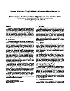
Due to traffic interception, traffic redirection to a simulation model, and the optional node virtualization, the architecture of VirtualMesh introduces some additional delays to the system. We have therefore performed several experiments in order to quantify these delays and detect possible bottlenecks. To determine the round-trip times (RTT), we have used simple ping (ICMP echo) measurements in a network similiar to the one in Figure 2. The network consists of one computer hosting the simulation model (OMNeT++ 3.4b2), two real nodes with VirtualMesh interfaces (PCEngines ALIX3), and one computer with host virtualization (XEN 3.2.1) holding several virtual node instances. The two hosts (Pentium D 930 3GHz, 2 GB RAM) and the nodes are interconnected by a 1 Gbps Ethernet network. Our evaluation includes the latencies/delays introduced by the network including virtualization, the traffic interception/redirection, and by the model. In the following figures, each data set represents measurement series of 100 ICMP echoes. The results are shown as boxplots, i.e. a bold line marks the median value, box lines represent lower and upper quartiles, and the circles mark outliers. First, we measured three different network latencies, i.e., between two physical hosts, between a physical host and a para-virtualized host, and between a physical host and a full-virtualized host. Full virtualization provides a complete simulation of the underlying hardware. A full-virtualized host therefore uses the real device drivers which then work on top of an emulated hardware layer. All software including the operating sytem and device drivers runs unmodified, in the same way as on the raw hardware. In contrast, paravirtualization introduces some adaptations to the guest operating system. The software interface of a para-virtualized
0.9
0.35
0.8
0.3
0.7 0.25 RTT [ms]
RTT [ms]
0.6 0.5 0.4 0.3
0.2 0.15 0.1
0.2 0.05
0.1 0
0 (a)
(b)
(c)
(a)
(b)
Scenario
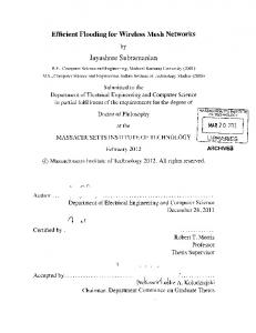
machine is similar but not identical to that of real hardware. Therefore, the drivers for network and block devices are replaced. In our scenario, the para-virtualized host employs our standard embedded Linux system which is also running on a real node. It makes use of the new para-virtualization feature of recent Linux kernels (paravirt ops) that allows it to run on native hardware and as para-virtualized machine. The para-virtualized kernel accesses the network and block devices through a Xen specific driver. The main advantage of para-virtualization is its improved performance compared to full virtualization. Our results in Figure 7 confirm that the additional delay introduced by virtualization is nearly negligible with less than 0.2ms for communication between a physical host and another physical host (a), or between a physical host and a para-virtualized host (b). If we replace the para-virtualized node with a fully virtualized node the delay obviously significantly increases due to the hardware emulation layer (see (c) in Figure 7). It still remains acceptable with 0.35ms, though. Nevertheless, we decided to use para-virtualization for VirtualMesh as it introduces nearly half the delay. Moreover, the standard Linux kernel already includes the paravirtualization features by default. The introduced delay by the traffic redirection should be as small as possible in order to have no significant influence on the simulated wireless network as the hardware behaviour is simulated in the simulation model. Moreover, the replacement of the Ethernet driver does not affect the accuracy of VirtualMesh. The second experiment evaluates the delay introduced by the PacketModeller (see Figure 8). RTTs between two virtual hosts with and without traffic interception by virtual interface vif0 and PacketModeller are measured. The result shows a moderate increase of less than 0.15ms which is nearly negligible. Our third experiment is showing the additional delays introduced by packet processing through the simulation model (see Figure 9). Packet processing in the current version of VirtualMesh is about 3ms for two context switches between real space to simulated space including simple processing inside the model (a). Our one-hop and two-hops measurements match this result approximately with 7ms for four context switches (b) and 10ms for eight context switches (c). The RTT of 22ms for the three-hop measurement with twelve context switches between real network and the simu-
Figure 8: RTT between two virtualized nodes without PacketModeller (a) and with PacketModeller (b) 25 Processing Time and RTT [ms]
Figure 7: Network latency between two hosts: physical host to physical host (a), to para-virtualized host (b), and to fully virtualized node (c).
Scenario
20 15 10 5 0 (a)
(b)
(c)
(d)
Scenario
Figure 9: Processing latency of the simulation model (a) and the resulting RTTs for a one-hop (b), twohops (c), and three-hops (d) connection. lation shows some increased delay, which has to be evaluated in more detail. We further performed some TCP throughput measurements by the simple FTP file transfer over multiple hops. The results are shown in Figure 10. The retrieved throughput values with 34 Mbps for the one-hop connection, 15 Mbps for the two-hop connection, and 7.5 Mbps for the three-hop connection make us confident that VirtualMesh is a valuable infrastructure for the pre-deployment testing of WMNs. Furthermore, they show a significant decrease of the throughput depending on the number of hops similar to the 1/(hop count) decrease shown in literature [12, 13].
4. CONCLUSIONS After development and evaluation with network simulators, Wireless Mesh communication solutions require extensive pre-deployment testing of their target platform implementations. This is difficult to achieve in a real test-bed as irrepressible sources of interference exist. Furthermore, the variety of testing topologies is limited and mobility tests are impracticable. Therefore, we propose VirtualMesh as a new testing architecture to be used before going to a real testbed. VirtualMesh is based on interception of wireless traffic at nodes and redirection to a simulation model that provides more flexibility and a controllable environment.
40
Throughput [Mbps]
35
[6]
30 25 20 15 10
[7]
5 0 (a)
(b)
(c)
Scenario
[8] Figure 10: TCP throughput measurements for onehop (a), two-hops (b), and three-hops connections (c). [9] The wireless drivers of the nodes are replaced by a virtual device which redirects the traffic to an OMNeT++ simulation model instead of transmitting it over the air. This is fully transparent to the Linux network stack and the applications. The virtual driver further acts in the same way than a wireless network driver under Linux and all configuration parameters may be set using the usual configuration tools. Our experiments have proven the functionality of the VirtualMesh testing infrastructure. VirtualMesh introduces negligible additional delays for the traffic redirection and moderate delays per real node inside a simulated path. The TCP throughput measurements show the ability of VirtualMesh to handle enough traffic to be used as a pre-deployment testing system.
[10]
[11]
[12]
5.
ACKNOWLEDGMENTS
The work presented in this paper was partly supported by the Swiss National Science Foundation under grant number 200020-113677/1.
6.
[13]
REFERENCES
[1] I. F. Akyildiz and X. Wang. A survey on wireless mesh networks. Communications Magazine, IEEE, 43(9):S23–S30, 2005. [2] P. Barham, B. Dragovic, K. Fraser, S. Hand, and T. Harris. Xen and the art of virtualization. In 9th ACM symposium on Operating systems principles (SOSP), Bolton Landing, NY, USA, October 19-22 2003. [3] J. C. Bicket, D. Aguayo, S. Biswas, and R. Morris. Architecture and evaluation of an unplanned 802.11b mesh network. In 11th Annual International Conference on Mobile Computing and Networking (MOBICOM 2005), pages 31–42, Cologne, Germany, August 28 - September 2 2005. [4] R. Bless and M. Doll. Integration of the freebsd tcp/ip-stack into the discrete event simulator omnet++. In 36th conference on Winter simulation (WSC ’04), pages 1556–1561, 2004. [5] R. Draves, J. Padhye, and B. Zill. Routing in multi-radio, multi-hop wireless mesh networks. In 10th annual international conference on Mobile computing
[14]
[15]
[16]
[17]
and networking (MobiCom ’04), pages 114–128, New York, NY, USA, 2004. M. Engel, M. Smith, S. Hanemann, and B. Freisleben. Wireless ad-hoc network emulation using microkernel-based virtual linuxsystems. In 5th EUROSIM Congress on Modeling and Simulation, pages 198–203, Cite Descartes, Marne la Vallee, France, September 6-10 2004. S. Ivanov, A. Herms, and G. Lukas. Experimental validation of the ns-2 wireless model using simulation, emulation, and real network. In 4th Workshop on Mobile Ad-Hoc Networks (WMAN’07), pages 433–444, Bern, Switzerland, February 26 - March 2 2007. S. Jansen and A. McGregor. Performance, validation and testing with the network simulation cradle. In 14th IEEE International Symposium on Modeling, Analysis, and Simulation (MASCOTS ’06), pages 355–362, Washington, DC, USA, 2006. R. Karrer, A. Sabharwal, and E. Knightly. Enabling large-scale wireless broadband: The case for taps. In 2nd Workshop on Hot Topics in Networks (Hot-Nets II), Cambridge, MA, USA, November 2003. T. Krop, M. Bredel, M. Hollick, and R. Steinmetz. Jist/mobnet: combined simulation, emulation, and real-world testbed for ad hoc networks. In WinTECH ’07, pages 27–34, New York, NY, USA, 2007. ACM. D. Raychaudhuri, I. Seskar, M. Ott, S. Ganu, K. Ramachandran, H. Kremo, R. Siracusa, H. Liu, and M. Singh. Overview of the ORBIT radio grid testbed for evaluation of next-generation wireless network protocols. In IEEE Wireless Communications and Networking Conference (WCNC 2005), volume 3, pages 1664 – 1669, March 2005. D. Sun and H. Man. Performance comparison of transport control protocols over mobile ad hoc networks. Personal, Indoor and Mobile Radio Communications, 2001 12th IEEE International Symposium on, 2:G–83–G–87 vol.2, Sep/Oct 2001. C.-K. Toh, M. Delwar, and D. Allen. Evaluating the communication performance of an ad hoc wireless network. Wireless Communications, IEEE Transactions on, 1(3):402–414, Jul 2002. A. Varga. The omnet++ discrete event simulation system. In European Simulation Multiconference (ESM’2001), Prague, Czech Republic, June 6-9 2001. E. Weing¨ artner, F. Schmidt, T. Heer, and K. Wehrle. Synchronized network emulation: matching prototypes with complex simulations. SIGMETRICS Perform. Eval. Rev., 36(2):58–63, 2008. Y. Zhang and W. Li. An integrated environment for testing mobile ad-hoc networks. In 3rd ACM international symposium on Mobile ad hoc networking & computing (MobiHoc ’02), pages 104–111, New York, NY, USA, 2002. ACM. A. Zimmermann, M. Gunes, M. Wenig, U. Meis, and J. Ritzerfeld. How to study wireless mesh networks: A hybrid testbed approach. Advanced Information Networking and Applications, 2007 (AINA ’07), pages 853–860, May 2007.