ViSE: Visual Search Engine Using Multiple Networked Cameras U. Park and A. K. Jain Michigan State Univ., USA {parkunsa, jain}@cse.msu.edu
I. Kitahara Univ. of Tsukuba, Japan
[email protected]
Abstract We propose a Visual Search Engine (ViSE) as a semi-automatic component in a surveillance system using networked cameras. The ViSE aims to assist the monitoring operation of huge amounts of captured video streams, which tracks and finds people in the video based on their primitive features with the interaction of a human operator. We address the issues of object detection and tracking, shadow suppression and color-based recognition for the proposed system. The experimental results on a set of video data with ten subjects showed that ViSE retrieves correct candidates with 83% recall at 83% precision.
1. Introduction With increasing concerns over security, surveillance cameras have become almost ubiquitous in public and private places. However, most of the surveillance cameras were initially installed with limited functionalities of providing video stream to human operators for later reviews of incidents or accidents. Recently, preventing crime in real time is the imminent function for video surveillance systems. Many studies on automated surveillance systems that utilize computer vision and image processing techniques have been reported [1,2,3]. The automation of surveillance systems will not only increase the number of manageable cameras per operator but it will also remove the necessity of video recording by correctly pointing out the critical events in real-time. With the difficulties encountered in fully automating the surveillance systems, semi-automatic surveillance systems that can effectively utilize human intelligence through the interaction with surveillance systems are becoming the main stream. An example commercial system can be found at [4]. In contrast to the conventional viewpoint of partitioning surveillance systems into human intervention and camera systems, we decompose the surveillance systems into three different parts: (i)
The 18th International Conference on Pattern Recognition (ICPR'06) 0-7695-2521-0/06 $20.00 © 2006
K. Kogure and N. Hagita ATR, Japan {kogure, hagita}@atr.jp
human intervention, (ii) Visual Search Engine (ViSE) and (iii) conventional camera system. Human operator translates high-level queries such as “Is this a suspicious person?” or “Where is the person X?” into low-level queries with primitive (image) features that can be understood easily by ViSE. The translation of the query is performed based on the knowledge of the operator. For example, the best visual features of a missing child can be provided by his parents. Examples of low-level queries with primitive features are “Show all subjects wearing blue shirt,” or “Show all subjects that passed location Y.” For the purpose of finding a person, ViSE narrows down the candidates and the human operator choose the final target. To be able to interact with human operators, ViSE processes input video streams and stores primitive features for all the objects of interest in the video. The block diagram of the proposed system is shown in Fig. 1.
Human Operator • Intelligent highlevel decision • Generate queries with primitive features
Visual Search Engine (ViSE) • Labor-intensive image processing • Primitive feature extraction • Answer to operator
Conventional Surveillance Camera System • Video-stream capture and optional recording
Figure 1. Proposed surveillance system. The ViSE is a bridge between the human operators and surveillance camera systems. Another trend in developing surveillance camera systems is using networked cameras. Networked cameras simplify installation and maintenance process and, in turn, enable monitoring large areas. Networked cameras use compressed images due to the limited bandwidth. The noise involved in networked cameras due to the image compression will be addressed in our image processing algorithms
2. Object Detection 2.1 Background Subtraction
The first step in processing video input is detecting objects of interest. A well-known method of object detection is based on the frame differencing of the current frame against a reference frame [5,6] or a few adjacent frames [7]. The background subtraction method against a reference frame is preferred to the inter-frame subtraction method for detecting stationary objects. However, the approach is too noise-sensitive to be used in our system, because of the additional source of noise in networked cameras. We propose a slight variation of the Gaussian background modeling method. Our approach estimates the background model both at the pixel level and at the image level. Let It(x,y) be the image captured at time t and let ΒN = {It(x,y)|t=1,2,…, N} be the set of images used in the background modeling. In a recursive fashion, the mean μ(x,y) and standard deviation σ(x,y) for each pixel can be calculated as t −1 x μ n−1 + n t t
(1)
( x − μn )2 , (n − 1) 2 σ n−1 + n n n −1
(2)
μn =
σ n2 =
(3)
or foreground, otherwise. Setting the value of k to 3, for example, it is expected that the model will include 99.73% of the background pixels if the distribution of pixel values is Gaussian. However, due to the violation of Gaussian assumption in practice, additional noise due to the image compression and the limited data in building the background model, Eq. (3) results in many false classifications of background pixels as foreground. These false classifications can be suppressed by introducing additional thresholds in Eq. (3), which can be obtained from the secondary mean μ ' and standard deviation σ ' computed as μ' =
σ '=
1 ∑ σ ( x, y ) x ⋅ y x, y
1 ∑ (σ ( x, y ) − μ ' ) 2 . x ⋅ y x, y
(5)
(8)
where new denotes the newly added pixel values and old denotes the pixel values to be removed. The secondary parameters μ’ and σ’ are also updated from the new σ(x,y). By keeping only N images in the buffer and updating the background model, no false detections due to background changes persist over N frames, an improvement over other background modeling methods. However, since part of an object that is static for N frames can be misclassified as background, a user intervention is also allowed to initialize and update the background model.
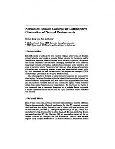
We first perform the proposed background subtraction in RGB space and then remove shadows from the second pass background subtraction in the HSV space. To save the computation, first pass subtraction is performed in V space and second pass subtraction is performed in H and S space. The second pass subtraction is also performed only on the foreground pixels whose V value is decreased from the background (i.e., μ(x,y)). The difference between background subtraction in V and HS spaces is shown in Fig. 2, where V space subtraction shows clear background but includes the shadow. The HS space subtraction, on the other hand, shows the advantage of shadow suppression.
(a) V space
(b) HS space
(c) V-HS space
Figure 2. Background subtraction
(6)
As the camera captures a new frame, the new image Inew(x,y) replaces the old image Iold(x,y) in ΒN and the
The 18th International Conference on Pattern Recognition (ICPR'06) 0-7695-2521-0/06 $20.00 © 2006
(7)
(4)
The parameters μ(x,y) and σ(x,y) and μ ' and σ ' account for the background model at the pixel level and the image level, respectively. The new criterion to decide a pixel as background is |I t - μ | < k ⋅ σ + (μ ' + k ⋅ σ ') .
new − old N (new − μ new ) 2 − (old − μ old ) 2 2 2 σ new = σ old + + N ( μ new − μ old ){( new − μ new ) + (old − μ old )} N
μ new = μold +
2.1 Suppression of Shadows
where n=1,2,…,N. Once μ and σ are obtained, a pixel can be decided as background if |I t (x, y ) - μ (x, y )| < k ⋅ σ (x, y ) ,
background model is updated by recursively updating
μ(x,y) and σ(x,y) as
3. Object Tracking 3.1. Homography-based Location Estimation Homography is a mapping function between two different 2D projection images of a 3D scene. It is well known that the homography between two images is obtained by four corresponding points. Using this, we
transform the 2D motion segmented image into the 2D representation of the floor (foot) print (i.e., surveillance area) to obtain the location of the subjects from the top-view. Two base homographic transformations H0 and Hh are calculated from four observed points in the image at heights 0 and h. Then, the homographic transformation at a height between 0 and h is calculated based on the following interpolation Hx =
(h − x) H 0 + x ⋅ H h . h
(9)
The location of a person can be measured by integrating the multiple transformed planes and detecting the peak value from the integration as h
location = max(C × ∫ H y ⋅S dy ) , x, z
(10)
networked cameras. In addition, those selected primitive features are easy for human operators to remember because they are commonly used in the real world.
4.1. Clothing Color The detected blob of a person is divided into three parts from top to bottom (at 1/5th and 3/5th of the height). The combination of the colors of middle and bottom parts is considered as the primitive color features of the person. One problem in color matching is that the observed color values in the RGB space from different cameras vary as much as those observed in different instances from the same camera as shown in Fig. 3.
0
where C is a cylindrical object for the convolution operation. This location estimation method can suppress the segmentation error, such as cracks and holes that are caused by the additional source of noise in networked cameras.
(a)
3.2. Kalman Filter In accumulating the moving path of a subject, conventional linear Kalman filter [8] is used for prediction and smoothing. The Kalman filter can be formulated in prediction stage as xk = Axˆk −1 + Bu k −1
(11)
Pk = APk −1 AT + Q
and correction stage as K k = Pk H T ( HPk H T + R ) −1 xˆk = xk + K k ( z k − Hxk )
(12)
Pk = ( I − K k H ) Pk
where xk is predicted state, xˆk is corrected state with measurement, zk is the measurement, Q is process noise covariance, R is measurement noise covariance, A denotes parameters that relate the state from k-1 to k, B relates u to the state x, H relates x to z, P is the estimation error covariance and K is the Kalman gain.
(b)
(c)
(d)
Figure 3. Intra- and inter-camera variations of observed color values. (a) original color values, (b) observed color values from camera 1, (c) camera 2 and (d) camera 3 at three different time instances. By removing the lightness component (V component) in the HSV color space, the color variation can be greatly reduced. Saturation also causes variations in color values from pure to dark but in the same color label. We propose a color-matching scheme by using Hue as the main component with the assistance of Saturation and Value. The color is decided mainly according to the Hue and the possibility of color being white, black or gray is decided by S and V. A histogram with ten bins (red, brown, yellow, green, blue, violet, pink, white, black and gray) is constructed from every pixel in the object segmentation. The decision threshold for each color is made from the boundary values in standard color charts. Final color is decided as the bin with the largest count.
4. Primitive Feature Extraction 4.2. Height To be able to make the communication between human operator and surveillance system, it is critical to select primitive features that can be understood and processed at both ends. We chose clothing color, height and build of the subjects as primitive features that can be easily computed at a distance using
The 18th International Conference on Pattern Recognition (ICPR'06) 0-7695-2521-0/06 $20.00 © 2006
The height of the person is estimated as the y-value at the location of a subject in Eq. 10.
4.3. Body Build
Build of the body is decided by the aspect ratio of the bounding box of each blob. Suppressing shadows is critical in obtaining the correct aspect ratios.
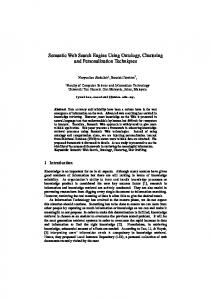
5. Experimental Results We collected three instances of video recordings from five people and one instance of video recording from another five people using three networked cameras installed in a hallway. Durations of video clips are between 25~30 seconds with ten frames per second. Since one instance of video recording generates three video clips from three different cameras, the total number of video clips is sixty. We evaluated the performance of ViSE in terms of the accuracy of feature extraction and the precision and recall for the subject retrieval. Given the set of prerecorded video data with ten different subjects, ViSE showed 93% overall accuracy in color feature extraction, less than 2 cm’ average deviation in height measurement and build values are observed to be distributed between 0.33 and 0.49. At 79% precision, the recall subject retrieval is 85% using only color features. Using color and height, the recall is decreased to 83% with increased precision of 83%. Some example search results using ViSE are shown in Fig. 4. It can be seen that ViSE is able to retrieve correct candidates and, in turn, significantly reduce the operator’s burden. Input Videos
Queries
Search Results
Blue shirt?
(ViSE) using multiple networked cameras. A robust background modeling method that can handle the images from networked cameras, shadow suppression, and a number of primitive feature extraction methods are introduced. The system has been tested with a prerecorded video data and shows promising performance. The proposed feature extraction method can be used in automatic single or cross camera tracking as well, where robust and invariant feature extraction is important. Future work will include increasing the accuracy of feature extraction, exploring additional primitive features and enhancing the user interface of the system.
Acknowledgements This research was done at ATR and was supported by the National Institute of Information and Communications Technology.
References [1] A.R. Dick and M.J. Brooks, “Issues in automated visual surveillance,” Proc. VIIth Digital Image Comp. Tech. and App., pp.195–204, Sydney, Dec. 2003. [2] Yi-Leh Wu, Long Jiao, Gang Wu, Edward Y. Chang, and Yuan-Fang Wang, “Invariant Feature Extraction and Biased Statistical Inference for Video Surveillance,” Proc. AVSS, pp. 284-289, 2003.G [3] O. Javed, Z. Rasheed, O. Alatas, and M. Shah, “KNIGHTM: A real-time surveillance system for multiple overlapping and non-overlapping cameras,” Proc. ICME03, pp. 649-652, Baltimore, July 2003. [4] PROXIMEX SURVEILLINT™ (Command & Control, EZ-Catalogue and EZ-Search), http://www.proximex.com
Black shirt?
Brown shirt & Blue pants?
Figure 4. Schematic Diagram of ViSE.
6. Conclusions and Future Work We have developed a semi-automatic surveillance system with the concept of Visual Search Engine
The 18th International Conference on Pattern Recognition (ICPR'06) 0-7695-2521-0/06 $20.00 © 2006
[5] R. Cucchiara, C. Grana, M. Piccardi, and A. Prati, “Detecting moving objects, ghosts, and shadows in video streams,” IEEE Trans. PAMI, vol. 25, no. 10, pp. 1337-1343, 2003. [6] I. Pavlidis, V. Morellas, P. Tsiamyrtzis, and S. Harp, “Urban surveillance systems: from the laboratory to the commercial world,” Proc. IEEE, vol. 89, no. 10, pp. 1478497, 2001. [7] C. Anderson, Peter Burt, and G. van der Wal, “Change detection and tracking using pyramid transformation techniques,” Proc. SPIE - Intelligent Robots and Comp. Vision, vol. 579, pp. 72-78, 1985. [8] G. Welch, G. Bishop, “An introduction to the Kalman filter,” Technical Report No. TR 95-041, Department of Computer Science, Univ. of North Carolina, March 2003.