frameworks as WMVC-based web applications. Developing such applications are equivalent to creating a set of related workflows [1,7,15] where each workflow ...
2011 International Conference on Communications and Information Technology (ICCIT), Aqaba
Visual Management of Workflows in Web Development Frameworks Marcel Karam, Haidar Safa, Hanan Mneimneh Department of Computer Science American University of Beirut, Lebanon
Joumana Dargham Department of Computer Science
Balamand University Lebanon
Keywords-component; Workflow; MVC; Visual Modeling
INTRODUCTION
Many industrial strength WMVC-WDFs such as Struts©[3] Ruby on Rails© [13], and PHP on TRAX© [14] have incorporated the concept of a workflow to define the transitions between the views of the application that are triggered by user interactions when performing a specific task. We refer to the applications that are instantiated using such frameworks as WMVC-based web applications. Developing such applications are equivalent to creating a set of related workflows [1,7,15] where each workflow is made up of a set of models and a set of views that are linked by a set of transitions that define the relationships between those entities. As such, each workflow is associated with a state, and the states of all workflows define the global state of the instantiated web application. In general WMVC-WDFs aid developers in generating the workflows in a WMVC web application but do not provide a way to map the workflows’ related code to visual artifacts; a feature that can help to inspect the correct formation and relationships of these workflows; especially if these artifacts are rendered the same browser where the application is running. Despite this pressing need [6, 7], we haven’t come across any work that addresses this issue. For example, the work in [12] does not allow the developer to visualize workflows and their direct relationships to the code; rather, a higher level of business workflow is presented to help developers perform mental link. The work in [5] recommended developing a visual approach for explicitly specifying temporal operators. The work in [7] looked at exception handling in workflows and in [6] they looked at the role of visual tools in web framework verification.
II.
RELATED WORK
Various attempts at managing workflows in frameworks that integrate the workflow concept with the MVC have been taking. The majority of that work focused on the high level representation or business workflows [1, 11]. Some focused on creating formal notation to represent workflows and their visual representation to represent the workflows [6], while others focused on resolving exception handling in workflows [7]. In this work our approach focuses on providing a visual environment to help developers manage their workflows in ROR applications. III.
CONCEPTUAL MODELING OF WMVC WEB APPLICATIONS
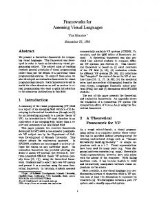
Developing a WMVC-based web application ψ requires the creation of a set of workflows W = {w1, w2 ,..., ww} where wi ∈W is a workflow in ψ is made up of a set of models M = {m1, m2 ,…, mm} and a set of views V = {v1, v2 ,…, vv}that are linked together based on a set of transition rules. The cn or control in ψ always resides at either a model or view within a particular wi in W. The cn could move within wi or redirect to another workflow wj based on a certain transition rule. The transition rule is based on an event. Each workflow wi in W in ψ can then be represented with a Local State Machine or LSM(wi) = (N, E, nwi) where N is the set of local nodes representing the models and views within wi, node nwi represents the entry node to wi, and E is the set of local transitions that link nodes in N based on a local transition. E also contains a dummy local transition that links nwi to the first node n1 ∈ N. Figure 1 shows LSM(w1) and LSM(w2).
ICCIT 2010- IEEE 2010, Jordan, March ©2010 IEEE 978-1-4577-0400-0/11/$26.00 ©2011 IEEE
Departement Informatique Université du Québec à Chicoutimi, Canada
Our approach is distinguished from other approaches in that we provide visual management of workflows at the method/code level. In this work, we provide, in the context of Ruby on Rail (ROR), a technique for the visual generation and inspection of workflows in WMVC web application. The rest of the paper is organized as follows. In Section 2 we discuss related work. In Section 3, we describe the conceptual modeling of MVC web applications as a set of interconnected state machines. In Section 4 we describe the way we implemented our visual workflow environment in the context of a “mini” banking application. We also describe the user interface of our visualization environment and its immediate and potential benefits. In Section 5, we conclude with a list of potential future work.
Abstract—Web development frameworks (WDFs) that incorporate both Workflow paradigms and the Model View Controller (MVC) [8] are known as WMVC-WFDs. Such frameworks guide the developer in generating the flow of control between the various components. Despite the pressing need for a visual environment to help developers manage the overwhelming number workflows during development, we have not come across any work that addresses this legitimate concern. In this work we describe, in the context of Ruby on Rail (ROR), an abstract model for the visual generation and management of workflows in WMVC-based web application.
I.
Hamid Mcheick
7
. The view uses these tags to display the data of the model to the user. For example, in Figure 2 (the webpage), the data from customers (id, name, family, username) is displayed. The view is also an entry point to the web application through which the user can submit requests by triggering events through various fields. For example, in Figure 2 (the webpage), he user can trigger events after pressing the Login or New Buttons.
Figure 1. A partial global state machine with two workflows.
An inter-workflow transition is a transition between nodes in the same workflow, and is defined as follows: [n1, n2, le], such that n1, n2 ∈ N and le is the local event that is generated by n1 and that moves the control from n1 to n2. As depicted in Figure 1 the transition between m1 and v1 in w1 is an interworkflow transition. The dummy transition [nwi, n1, de] automatically links node nwi to node n1 ∈ N, such that de acts as a dummy event. A transition between a node in wi and a node in wj is an inter-workflow transition. For example, as depicted in Figure 1, the transition between v1 and nw2 is an interworkflow transition. The collection of all workflows and both their intra and inter workflow transitions comprise the Global State Machine (GSM) in ψ. More formally, GSM = {LSM(w1), LSM(w2) ,…, LSM(ww)}, where each global node LSM(wi) in the GSM represents a workflow wi ∈ W. LSM(w) is a sub-graph that corresponds to the LSM of w ∈ W. These sub-graphs or global nodes are linked by global transitions that cause the redirection from a local node in a particular LSM(wi) to the entry node (nwj) of (LSM(wj)). We represent the global transition as follows [n, nwj, ge] where n is a local node in LSM(wi), nwj is the entry node of LSM(wj), and ge is the global event that is generated by n and that moves the control from n to LSM(wj). We consider that each application ψ has a Home or index page that acts as the entry to the system through which the user can access the various functionalities of the web application. Therefore, any action in any controller can be reached if the control starts at the index page. IV.
The Controller - Each controller is made up of a set of methods called actions. Each action is associated with a user’s HTTP request with the following form: (controller/action/id). When the request is received by the server, the action specified by the request in the controller will be invoked to execute the instruction on the row in the database having the corresponding id. More specifically, an action can contact some models, manipulate their data as requested by the user, render a view, and/or redirect the control to other actions in the same or different controller. Each action can have a corresponding view in the views folder with the same name as its action but with a .rhtml extension. If such a view exists in the views folder, the view is implicitly rendered when the action executes its last statement; otherwise, an error view is displayed if no redirection to other action occurs. The view can also access any instance variable defined in its corresponding action to display the data to the user. To further illustrate on the role of the controller, consider a login scenario in the context of our running example. In the login scenario, a client first accesses the index web page of the banking application and submits his/her credentials. If the system verifies the login attempt, the client will be directed to his/her personal web page; else s/he will be directed back to the index page. To call the index page of the banking application, the client should submit the following request customer/index that calls the index action of the CustomerController. The index action renders the view index.rhtml which is found in the views folder. The state of the index view is dictated by two active buttons that allow the following events e = {login, new} to be triggered as shown in Figure 2.
WMVC SUPPORT IN RUBY ON RAIL AND IMPLEMENTATION
In this section, we explain, in the context of a login senario of a “mini” banking application example, how ROR supports the common components of the WMVC web application. The “mini” online banking web application allows clients to deposit and withdraw money to or from their accounts. It also allows them to check their balances, create a new account, and update their personal information. This web application is based on two database tables: customers (id, name, family, username, and password) and accounts (id, account-number, branch, balance, and customer-id). As previously mentioned, ROR guides the developer to divide the “mini” banking application, as into three main folders: models; views; and controllers
def login @tryme = @params['customer'] @pleaseusr= @tryme['username'] @pleasepsw= @tryme['password'] if huser = Customer.find_by_username_and_password( @pleaseusr,@ pleasepsw) redirect_to :action => 'show', :id => user.id else redirect_to :action => 'index' end end
The Model - The model is an OO Ruby class that represents a table in the database. Each object or instance of this class represents a row in a database table and contains the domain logic unique to that object, that is, the models represent the domain objects of ROR applications. Manipulating the model using its methods and instance variables is usually handled in the controller.
Figure 2. The index view.
When the client submits his/her credentials and presses the login button, the login action in the Customer-Controller will be called since this button is associated with the URL: customer/login. The login action sends a message (find_by_username_and_password) to the Customer model that will check if the customers database table contains a matching instance of the submitted credentials. If such an
The View - The default view pages are HTML-based pages with support for special RHTML tags; or
8
instance is found the Customer model generates a true event that directs the system to the show action in the CustomerController; else it generates a false event that directs the system back to the index action. The code of the login action is presented in Figure 2 (the code). In the show action depicted in Figure 3 (the webpage), the Customer model is sent a find message that returns a model object whose instance variables are populated with the values of the attributes belonging to the requested row in the customers table. The returned object is stored in the instance variable (@customer) of the controller class. Once the find method returns, the control will be directed from the model to the show view that will be implicitly displayed when the show action executes its statement. The show view accesses the @customer variable defined in the show action to present the model’s data to the user as shown in Figure 3 (the code). For example, to print the name of the customer in a row of an HTML table, the code in Figure 3 is used.
view in w or the entry node of another action in case of interworkflow transition) where the control C will reside. For example, the Hw of Figure 5(b) in workflow w that is depicted in Figure 5(a) consists of two Key-Value (kw, pw) pairs: m1 =>{e1 => v1, e 3 => m2} and {m2 =>{e2 => v2}, such that, in the first pair, the key m1 is a model that generates two events e1 and e3 that redirect the control to v1 and m2, respectively; and in the second pair, the key m2 is a model that generates the event e2 that redirects the control to v2.
(a) LSM(W)
(b) Its corresponding HW
Figure 5. The hash data structure of an LSM(w)
GSM is also represented by a Hash data structure GH(W) having several key-value pairs (K, P) where K is the name of an action A corresponding to workflow w ∈W, and P is Hw representing LSM(w). For example, the HW in Figure 6 (b) of the GSM depicted in Figure 6 (a) consists of two Key-Value pairs: (W1, HW1) and (W2, HW2) where HW1 represents LSM(W1) and HW2 represents LSM(W1). We next describe how to populate Hw, and ultimately HW. HW = { W1= >{ m1 =>{ e1 => v1, e3 => m2}, m2 =>{ e2 => v2}, v1 =>{ e5=> W2} }, W2= >{ m3=>{ e4 => v4}}}
def show aaa@customer = Customer.find(@params['id']) end
Figure 3. The show action and its corresponding view. Figure 6. (a) A GSM and Its corresponding GH (b)
Based on its function, each action in a controller implements a particular workflow among a subset of the models and the views in the web application. Therefore, we consider each action in each controller class as a workflow. The set W of the actions or workflows in all the controller classes constitutes the ROR application (ψ). Figure 4 shows the interaction among the various actions (workflows) of the login scenario as previously explained.
We first create and initialize H for R, and then construct for each action A (method in R), hw of the corresponding w and add the pair (A, hw) to H. More specifically, for each controller class in the controllers of R, we use a Ruby parse-tree library [13]to extract its parse tree information which we then store in a list or L(PT). For each action A we encounter while traversing L(PT), we create and initialize a new hw. To populate hw, we traverse each statement in A and if we encounter an event (model-related message or a predicate statement [4] whose outcome depends on the interaction with a model), we store that event; however, if we encounter a model m, we add the key-value pair (m, pw (an empty hw)) to Hw provided that such pair does not already exist and check to see if an existing event e is stored. If found, we add the key-value pair (e, m) to hw that corresponds to the current state C and set the latter to m. If a redirect_to (a goto-like statement) is encountered and an event e is stored, we add the pair (e, A’) to hw that corresponds to the current state C where A’ is the action specified in the redirect_to. After traversing all the statements in A, we check if this action has a view v in the views files. If found and there is an event e stored, we add the pair (e, v) to hw that corresponds to the current state C, and set the latter to v. We also add the key-value pair (v, pw) to Hw, provided that such pair does not already exist. To populate pw or hw with the transitions directed out of v, we first parse the RHTML file of v using an HTML parser, and then loop over each field through which the user can trigger an event, and extract both
Figure 4. The inter and intra-workflow transitions in the login scenario.
A. Implementation Given a ROR application R, we implement each LSM(w) ∈ GSM = {LSM(w1), LSM(w2) ,..., LSM(wn)} as a set of Key-Value pairs (kw, pw) in a Hash data structure Hw,where kw represents a node n (model m or view v) in w, and pw is also a Hash structure H’w with several Key-Value pairs (k’w, p’w) where k’w is the event generated by n and p’w is the next node (model or
9
the event e and the request that will be submitted as the result of triggering e through this field. The HTTP request contains normally the name of action A’ to which the control will be redirected to. Once we extract e and A’, we add the pair (e, A’) to hw that corresponds to v. Finally, after traversing all the statements in the current action A and parsing its view, we add the pair (A, hw) to HW.
no longer valid. These colors help developers isolate dependencies and get better insight about the affect of code change. It can also help developers keep track of the workflows in accordance with the specification. This however is part of our future work. The second tab on the left hand side of Figure 7 allows the user to observe all the workflows (GSM) in one scrollable page. By examining the states linked by such transitions, the developer can detect, for example, if there is a reference to a non-existent state. Moreover, it could help detect incorrect state transition or cyclic state transition. By clicking on the cluster corresponding to the suspicious action A, the developer can view its related code highlighted (on the left hand side of Figure 7).
To collect the local transitions and the global transitions, respectively, in each LSM(w) and the GSM, we retrieve every pair (K, P) from H and extract all the local and global transitions. More specifically, for each pair (kw, pw) in hw, we extract each pair (k’w, p’w) from pw. If p’w is a local node (model or view) within w then [kw, p’w, k’w] represents a local transition. However, if p’w is a name of an action in R then [kw, p’w, k’w] represents a global transition.
V.
CONCLUSION AND FUTURE WORK
In this work, we provided techniques for the visual generation and management of workflows in web applications that are created with Ruby on Rails; a framework that integrates the concept of workflows in its MVC development environment. The tool is being scaled both at the interface and back-end levels to handle the following features which we like to pursue as future work: (a) automatic update of invalid references (after editing the code), and (b) perform dataflow analysis at the LSM and GSM levels and perhaps conduct a comparative study that looks at the test suite sizes and their effectiveness in finding faults, as opposed to traditional coverage techniques using traditional test suites. We suspect that the interface, albeit with the appropriate changes, will play a pivotal role in helping users locate faults. REFERENCES Figure 7. The interface of our tool showing the visual representation of two workflows (with three invalid references)
[1]
B. User Interface and Visual Workflows
[2]
We used the GraphR library to display the workflows of R since it provides a Ruby interface for DOT [2] which is a visualization tool that draws directed and undirected graphs. An important feature of DOT is that it allows clusters (subgraphs) to be drawn in their own distinct rectangle within a larger graph and to be connected together. Figure 7 shows the current interface where the visual workflows of the “login.rb” and “update.rb” (the files containing all the workflows of the login and update scenarios of customers in our banking example) are drawn using GraphR. The developer can type (http://127.0.0.1:3000/VisualWorkflow) in the browser where they are developing the code, and they’ll be presented with what is depicted in Figure 7. The left hand side contains two options; a local view and a global view tabs. In the local view, the user can see for each “.rb file” containing related workflow its corresponding visual workflows on the right hand side of the screen. Each transition in the right hand side view is implemented as a hyper link that takes the user to the related code once clicked. Inter and Intra transitions in the GSM are first colored black. When the user makes changes to the code, wants to check the validity of the changes and their effect on the workflows, the user can reload the web page, and observe which transition became invalid by looking at red arrows. The coloration of black arrows red indicates that the transition is
[3] [4]
[5] [6] [7] [8] [9] [10] [11] [12] [13] [14] [15]
10
Buddhima De Silva, Athula Ginige. Modeling web information systems for co-evolution. Proceedings of ICSOFT (ISDM/EHST/DC). 2007, 5461. E. Gansner, E. Koutsofios and S. North, "Drawing graphs with dot," Murray Hill, NJ, 2006. http://struts.apache.org (accessed Nov, 10, 2010). Hong Zhu, A Framework for Service-Oriented Testing of Web Services, 3rd International Workshop on Quality Assurance and Testing Webbased Applications, Proc. of COMPSAC’06, Sept. 2006, Chicago, USA, pp679-691. L. GuangChun, W. Yanhua, L. Xianliang and H. Hong, "A novel web application frame developed by MVC," SIGSOFT Softw. Eng. Notes, vol. 28, pp. 7, 2003. Marco Brambilla, Alin Deutsch, Liying Sui, and Victor Vianu. The Role of Visual Tools in a Web Application Design and Verification Framework: A Visual Notation for LTL Formulae. ICWE 2005. M. Brambilla, S. Ceri, S. Comai and C. Tziviskou. "Exception handling in work-flow-driven web applications," in WWW '05: Proceedings of the 14th International Conference on World Wide Web, 2005, pp. 170-179. S. Hansen and T. V. Fossum. "Refactoring model-view-controller," J. Comput. Small Coll., vol. 21, pp. 120-129, 2005. R. M. Lerner, "At the forge: assessing ruby on rails," Linux J., vol. 2006, pp. 10, 2006. T. Osterlie, "Ruby," Linux J., vol. 2002, pp. 4, 2002. Wenjun Wu Thomas D. Uram, Michael Wilde, Mark Hereld, Michael E. Papka. A Web 2.0-Based Scientific Application Framework. 2010 IEEE International Conference on Web Services. www.alienfactory.co.uk/strutsgui/ (accessed Nov, 10, 2010). www.rubyonrails.org/(accessed Nov, 10, 2010). www.rphpontrax.org/(accessed Nov, 10, 2010). Y. Shan, "An event-driven model-view-controller framework for smalltalk," in OOPSLA '89: Conference Proceedings on Object-Oriented Programming Systems, Languages and Applications, 1989, pp. 347-352.