Visualization of Areas of Interest in Software Architecture Diagrams H. Byelas∗ Technische Universiteit Eindhoven
Abstract Understanding complex software systems requires getting insight in how system properties, such as performance, trust, reliability, or structural attributes, correspond to the system architecture. Such properties can be seen as defining several ’areas of interest’ over the system architecture. We visualize areas of interest atop of system architecture diagrams using a new technique that minimizes visual clutter for multiple, overlapping areas for large diagrams, yet preserves the diagram layout familiar to designers. We illustrate our proposed techniques on several UML diagrams of complex, realworld systems. CR Categories: I.3.4 [Graphics Utilities]: Graphics editors— Paint systems; D.2.2 [Design Tools and Techniques]: Modules and interfaces—Computer-aided software engineering Keywords: UML diagrams, metrics, areas of interest, architecture visualization
1
Introduction
UML (or similar) diagrams are among the methods of choice for system architects and developers to describe and understand software architectures and designs, e.g. the structural and functional relations between the various interfaces, components, objects or roles in a system [IBM 2005; Borland 2005]. Complementing diagrams, software metrics effectively describe various aspects of complex systems, e.g. system stability, resource usage, design complexity, or performance [Dunke and Schmietendorf 2000; Gill and Grover 2003; Goulao and Abreu 2004]. Metrics can help answering targeted questions, e.g. ”which components are unstable or non-conforming to specific guidelines and requirements?” or ”what happens if I change this component?” [M¨oller et al. 2004] Software elements that share a common property are of particular interest in system analysis, e.g. ”all high-reliability components”, ”all components using over 1 MB of memory”, ”all components introduced in the system version 2.3”, or ”all components in the same thread” [Voinea and Telea 2004]. We call such a set of elements an area of interest (AOI). AOIs can be defined using software metrics [Fenton and Pfleeger 1998; Gill and Grover 2003; Goulao and Abreu 2004] which can be computed by existing analysis tools [Wust 2005; Bondarev et al. 2006, to appear]. Such AOIs, and their underlying metrics, are usually shown to users in a tabular format. We argue it is better to visually combine AOIs and UML (architecture) diagrams, to let users correlate concerns (described by AOIs) with system structure (diagrams). We present an ∗ e-mail:
[email protected] † e-mail:
[email protected]
A. Telea† Technische Universiteit Eindhoven approach that visualizes AOIs on UML-like diagrams in a simple to follow, scalable, and non-intrusive way. Users can easily navigate between views of classical diagrams and AOIs, yet preserve the familiar diagram layout. Our technique scales well when visualizing multiple, overlapping, AOIs on large diagrams, and works for any UML-like diagrams. This paper is structured as follows. Section 2 reviews related work in visualizing AOIs and diagram data. Section 3 presents our new techniques that render AOIs on diagrams effectively and efficiently. Section 4 presents several applications of our AOI drawing on real-life diagrams from the industry. Section 5 discusses our findings and the lessons learnt. Section 6 concludes the paper with directions of future work.
2
Related Work
We describe our AOI visualization on (UML) diagrams with the 5-dimensional model of Marcus et al. [Marcus et al. 2003]: task, audience, target, medium, representation. Our task is to understand how various (non)functional system aspects (the AOIs) map on some system description (the UML-like diagrams). Our audience includes mainly software architects. Our visualization target is a set of UML-like diagrams, together with AOIs specified as already computed software metrics for the diagram elements [Fenton and Pfleeger 1998]. The visualization medium is a modified UML diagram viewer [Termeer et al. 2005] that combines rendering diagrams and AOIs. Finally, the representation enriches classical box-and-line diagram drawings with AOIs drawn as smooth, soft-textured, shapes with a new technique. Modeling tools, e.g. Rational Rose [IBM 2005] or Together [Borland 2005], are accepted ways to visualize UML diagrams, but have little support for metric data, and still less for drawing metricdefined AOIs. Drawing AOIs as boxes AOI yields high visual clutter, as illustrated by the 12 AOIs drawn on the diagram in Fig. 16. Other tools, e.g. Rigi [Tilley et al. 1994] or MetricView [Termeer et al. 2005], can show an AOI by marking its elements with with icons scaled, colored, and shaped to show metric values. Yet, inferring AOIs from such markers is very hard for large diagrams having more than a few, overlapping, AOIs. One could also move all diagram elements in an AOI close to each other and draw a surrounding frame [Gansner and North 2000]. However, diagrams are often laid out manually with great care. Changing the layout every time one changes the AOIs destroys the user’s ’mental map’, a well known fact in information visualization. Methods such as metaballs [Rilling and Mudur 2002], H-BLOB [Sprenger et al. 2000], and 2D implicit surfaces [Balzer and Deussen 2005] draw AOIs as smooth shapes around their respective elements. Such shapes are computed as isosurfaces of some potential function, or distance field, based on the elements’ locations. However, it is hard to control both the smoothness and tightness of isosurfaces. The isosurface shapes and, worse, connectivity, highly depend on a correct isovalue, which cannot be easily chosen automatically [Sprenger et al. 2000]. Finally, distance fields and isosurfaces are computationally expensive. Recently, a method based on texture splatting has been proposed that efficiently draws smooth AOIs of controlled shape with minimal user intervention [Byelas and Telea 2006], using a technique called texture splatting. However, this method is limited in handling complex, overlapping AOIs on large diagrams.
3
New Proposal
We build on the texture splatting idea of [Byelas and Telea 2006], keeping its main features (high speed and minimal user input). Additionally, we add new techniques to solve the problems of the original method, i.e. we can easily handle many complex-shaped, overlapping, AOIs, and offer a simple and intuitive AOI shape smoothness and tightness control. Overall, the features of our method are as follows: 1. AOIs do not change a given diagram layout 2. There is low visual clutter between (overlapping) AOIs and diagrams, and AOIs themselves 3. AOIs drawing is real-time, even for large diagrams Our AOI visual design tries to mimic the way humans draw them with pencil on paper diagrams, as vague, sketchy, imperfect shapes that surround the concerned elements. We construct such shapes in two steps. First, we build an AOI skeleton from the elements’ size and position (Sec. 3.1). Next, we draw the AOI using a graphics technique called texture splatting (Sec. 3.2). These techniques are described next.
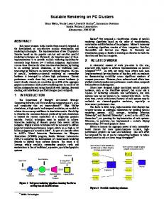
3.1
Figure 1: Construction of inner skeleton
Skeleton Construction
In Section 4, we shall compare, on real-world UML diagrams, the quality of the AOIs drawn using the skeleton proposed here and the skeleton proposed by the original AOI drawing method [Byelas and Telea 2006] respectively. To distinguish the two, we call the skeleton proposed by [Byelas and Telea 2006] an inner skeleton (since it is located at the center of the elements’ bounding box), and the skeleton we propose here an outer skeleton (since it is located at the periphery of the elements’ bounding box). We first briefly sketch the inner skeleton method (see also Fig. 1). For a diagram with elements ei having geometric centers ci , the inner skeleton is the line set (ci ,C), where C = ∑i Ai ci /∑i Ai is the area-weighted barycenter of the elements (Ai is the area of element ci ). Given element ei , with bounding box of width wi and height hi , a radius Ri = max(wi , hi ) is computed for ei and a radius R = kR ∑i Ai ci /∑i Ai for the center C as a fraction kR of the average radius. Setting the value for kR is explained in Section 3.2. Next, every line segment (ci ,C) is sampled with several points pi j spaced with some small distance δ = |pi − pi+1 |, e.g. δ = 0.1R. For every pi j , we compute also a radius ri j by linear interpolation between the radii R and Ri at the end of the segment (ci ,C). The inner skeleton is the set of points and radius values {(pi j , ri j )}. We now explain the outer skeleton construction. This has three steps (see Fig. 2 b-d). We start with the 2D bounding boxes (b1i , b2i , b3i , b4i ) of the elements ei in the AOI (Fig. 2 a). We first compute the convex hull C = {qi } of the corner points {bi j }, yielding the result in Fig. 2 b. This is the tightest convex polygon that encloses all our element bounding boxes, i.e. a possible approximation for an AOI shape. Still, we would like smoother, tighter fitting, shapes. To obtain this, we first subsample C (Fig. 2 c) such that the average distance δ between consecutive points |qi −qi+1 | is a given, small fraction of the convex hull perimeter |C| = ∑i |qi − qi+1 |. In practice, we set δ = 0.01|C|. Next, we deform the subsampled contour qi so that it fits tighter the elements inside and, at the same time, yields a smoother curve than the convex hull (Fig. 2 d). We deform the contour by moving every point qi to q0i : qi−1 + qi+1 (1) q0i = qi + εn~n + εs 2
Figure 2: Construction of outer skeleton Here, ~n is the normal to the line segment (qi−1 qi+1 ). Assuming {qi } are specified in counterclockwise order, qi will be moved inwards inside C. This serves two purposes. First, qi moves perpendicular to the contour with a distance εn which shrinks the contour, making it tighter. Second, qi moves towards the center of the line segment (qi−1 qi+1 ) with distance εs . This is the well-known geometric Laplacian smoothing [Taubin 2000] with factor εs applied to our contour, which guarantees to remove contour sharp corners. We do the move in Equation 1 only if d = min( min |qi − q j |, min |qi − p j |) > 2δ | j−i|>1
j
(2)
i.e. the contour point qi is farther from all element corners p j and other contour points q j (except its immediate neighbors q j−1 , q j+1 ) than a distance 2δ . This test prevents the contour to self intersect during deformation. We move all points until we reach a user-set stop criterion or a maximum number of iterations Nmax . Different stop criteria model different contour properties, as follows: • Stopping when the deformed contour area A(C) reaches a fraction fA < 1 of the initial contour area controls the tightness of the AOI shape. Smaller fA values mean tighter areas. Stopping after a given number of iterations N < Nmax does roughly the same and is also cheaper to implement. • Stopping when the deformed contour length |C| reaches a fraction fC > 1 of the initial contour length controls the smoothness of the AOI shape. Larger fC values mean less smooth contours.
Figure 8 shows several deformation steps for a simple AOI, starting from the convex hull until a quite tight shape, reached after 20 iterations. The parameter setting εn = 0.005|C| = 0.5δ ,εs = |qi−1 − qi+1 |/4, N ∈ [5..20] and fC ∈ [1, 2] give very good results in practice for all configurations (shape, position, and number of diagram elements). Besides preventing self-intersection, we must also prevent the contour to become too sparsely sampled, due to the contour length increase during deformation. We do this by checking the distances |qi −qi+1 | and |qi −qi−1 | between the moved point qi and its neighbors. If these exceed 2δ , we insert a new contour point halfway between qi and the respective neighbor. Checking for the contour becoming too densely sampled is not needed, as we know from shape processing that motion of lines (the initial convex hull edges) in (smoothed) normal direction always stretches the contour [Costa and Cesar 2001]. Fast convex hull and deformation computations are crucial for an efficient outer skeleton construction. We use the Triangle geometric library [Shewchuk 1996] which provides a state-of-the-art convex hull implementation. For the deformation, the distance testing in Equation 2 must be done very efficiently. A naive implementation would use O(NC(NC + E)) operations per deformation step for NC contour points and E elements, which is too slow for real-time performance. We solve this by using a fast spatial search structure that locates the nearest point q j to the moving point qi in O(log(NC + E)) operations, using kd-trees [Arya et al. 1998]. All in all, these choices let us deform complex contours containing hundreds of elements (E) and hundreds of contour points (NC) in sub-second time.
3.2
Drawing Areas by Skeleton Splatting
We now use the skeleton to draw the AOI, as follows. First, we construct a so-called splat. This is a radial function T (x, y) = p f ( x2 + y2 ). T looks as shown by Fig. 3 a (dark=opaque, light=transparent). Here, f is called the splat profile, or shape. We shall use f (x) = xk , so T increases linearly with the distance for k = 1, exponentially for k > 1 and logarithmically for k < 1 (see Fig. 3 b). We implement T as a transparency (also called alpha) texture with the OpenGL graphics library [Woo et al. 2001]. Hence, T = 0 yields fully transparent pixels and T = 1 fully opaque pixels.
Figure 4: Tightness and smoothness control (inner skeleton) (drawn with sharp, straight lines). This distinguishes the two visually. Splatting the inner AOI skeleton is a robust, simple and fast way to draw a shape that contains all elements in an AOI and has a simple, predictable ’look’. A first simple, but effective, improvement we propose with respect to the original method [Byelas and Telea 2006] is the choice of the radius factor kR (introduced in Sec. 3.1). The original method set kR to a small constant value kR = 0.1. We let users vary kR to control the tightness and smoothness of the AOI shape. Small (kR ∈ [0.1, 0.5]) values yield the typical tight star-shaped AOIs shown by the original method (Fig. 4 a). Large (kR ∈ [1, 3]) values yield rounded, softer shapes (Fig. 4 d). Inbetween kR values balance the trade-off between the shape smoothness and tightness (Fig. 4 b,c).
(a) inner skeletons
(b) outer skeletons
Figure 5: Areas of interest drawing styles
The inner skeleton method [Byelas and Telea 2006] rendered the AOI by drawing the texture T centered at every skeleton point pi j , scaled by the radius ri j , and colored by a user specified AOI color. Figure 5 a shows the result of this method for a simple diagram containing five elements and two areas of interest.
However useful, the inner skeleton AOI drawing has a major problem: It scales quite poorly for diagrams having overlapping AOIs of complex shapes (see e.g. Fig. 15 (bottom). The main problem of the inner skeletons is that they have a fixed, star-like, topology, i.e. a center connected to the elements’ centers. Inner skeletons work quite well for small-size AOIs (e.g. Fig. 5) or AOIs whose convex hull is close to a regular n-sided polygon, but not that well for more complex shapes (e.g. Fig. 16). Our outer skeletons solve this problem. Figure 5 b shows the same AOI as in Fig. 5 a, this time drawn using the outer skeleton, as explained next.
Several properties of this method are visible here. First, the AOI is visually quite different (i.e, soft and round) from the diagram
We draw the AOIs using the outer skeleton in two steps. First, we triangulate the deformed contour {qi } (Sec. 3.1) and render the re-
Figure 3: Splat texture(a) and texture profile (b)
more deformation iterations (e.g. 10..20) in outer skeleton mode. Conversely, if we want looser, more rounded areas, we use a high kR value (e.g. 2) in inner skeleton mode, or fewer deformation iterations (e.g. 5) in outer skeleton mode. Clearly, many other scenarios are possible too.
Figure 6: Contour splatting: (a) contour; details with (b) radial and (c) band splatting sulting triangles in the area’s color. This takes care of the area itself. Next, we would like to draw a soft, fuzzy contour, similar to the effect in Fig. 5 a for the inner skeleton drawing. We first tried the same idea of splatting the contour points with the radial texture. However, this requires a very high number of splats (roughly, one every few contour pixels) to produce relatively smooth border, which is quite inefficient. And the quality is still poor (see Fig. 6). The contour in Fig. 6 a is rendered with splats. We can see on the zoomed-in detail (Fig. 6 b) that, even though we are using a high splat density, the border looks jagged. We solved this problem by designed a better rendering method for the outer skeleton, as follows. We first offset the contour points qi outwards along the contour normal ~n: q0i = qi + εn~n (3) Here, ~n and εn are the same as in Equation 1. This creates a narrow band along the contour (Fig. 7 a). Next, we create a ’band’ texture T (x, y) = f (x) (Fig. 7 b) where f is the same profile as for the splat texture (Fig. 3) and use it to render the border quadrilaterals (qi qi+1 q0i+1 q0i ). This yields the soft border effect (Fig. 5 b) which looks very much like the soft edges of the inner skeleton rendering (Fig. 5 a). Compare also Fig. 6 c (drawn with the new method and using about 80% less contour point samples) with Fig. 6 b (drawn with radial splats).
Figure 8: Controlling tightness and smoothness (outer skeletons) A second variation our users found very intuitive and useful during our case studies (Sec. 4) was to draw AOIs as contours instead of filled shapes. For the inner skeletons, this is done in two passes. First, we draw the filled AOI using the splat textures, as described so far. Second, we draw the same AOI, using the same splat texture centered at the skeleton points, but now scaled to a smaller radius d ∗ ri j , and using the background color, e.g. white. d ∈ [0, 1] controls the contour width: d = 0 yields the filled shapes, and d ≈ 1 yields a very thin contour. As before, k controls the contour sharpness. Figure 9 (c,d) shows two examples of areas of interest drawn with contours with a contour width d = 0.8.
Figure 7: Soft border splatting for outer skeletons By controlling the various splatting parameters, we obtain visual effects useful for different user scenarios. If we want to draw ’hard’ AOIs with a sharp, precise, border, we set k < 1 for the texture profile (e.g. k = 0.3, Fig. 9 a). This is useful e.g. to show important system properties or metrics having a high confidence value. If we want to draw ’soft’, fuzzy AOIs, we set k > 1 (e.g. k = 5, Fig. 9 b). This is useful e.g. to show less important properties, which should not distract the eye from the more important diagram drawing, or metrics having a low confidence value. If we want to draw tight areas, we use a low kR value (e.g. 0.1) in inner skeleton mode, or
Figure 9: Filled and contoured areas (inner skeletons) However, contour drawing using the inner skeletons has the un-
pleasant property that it erases the inside of the contour. This leads to undesired effects when e.g. drawing multiple, overlapping AOIs, as shown in Fig. 11 a. This problem is easily solved when drawing AOI contours using the outer skeleton (Fig. 11 b,c). We do this by simply skipping drawing the triangulation and drawing only the soft contour band, this time using a mirrored band texture (Fig. 7 c) to make the border look symmetric. As shown in Fig. 11 b, we can now easily understand which elements are in which AOI, e.g. the upper-right element is in both AOIs. After our users experimented with this display mode one some large diagrams (see Sec. 4), they required the same intuitive display of overlapping AOIs also in filled area mode, not only contour mode. We solved this request using outer skeletons by using a special blending mode, as follows. First, we render the background black. Next, we render all AOIs using 1 − RGBi , where RGBi is the actual color of area i, in additive OpenGL blending mode. After all areas are rendered, we negate the image. The resulting color will be (see also Fig. 11) RGB = 1 − (max ∑ (1 − RGBi ))
(4)
i
The above means that areas are rendered as before where they do
3.3
Erasing Overlapping Components
Both inner and outer skeleton drawing methods described so far guarantee that the drawn shape visually surrounds all elements in the AOI. However, the drawn shape might surround, or overlap with, elements which are not in the AOI, but close to it, e.g. the marked one in Fig. 12. This is, of course, an undesired side effect. As explained in Sec. 1, one of our hard constraints is to never modify the diagram layout. Hence, we must find some other solution to visually show that the problem elements are actually not in the AOI they visually interfer with. We solve this problem as follows. First, we draw all AOIs as described so far. Next, for all elements not in any AOI, we draw an eraser texture. This is a transparency texture, like the splat texture (Fig. 3 a) used to draw the AOIs, except that it has a rectangular (instead of radial) shape (see Fig. 10 a) and a profile given by a slightly different function. Instead of f (x) = xk , we use now the following profile f (see also Fig 10): ( 1, x