energies Article
Voltage-Based Hot-Spot Detection Method for Photovoltaic String Using a Projector Yadong Wang 1,2 , Kazutaka Itako 1, *, Tsugutomo Kudoh 1 , Keishin Koh 1 and Qiang Ge 2 1
2
*
Department of Electrical and Electronic Engineering, Kanagawa Institute of Technology, Atsugi 243-0292, Japan;
[email protected] (Y.W.);
[email protected] (T.K.);
[email protected] (K.K.) Department of Energy and Power Engineering, Yangzhou University, Yangzhou 225000, China;
[email protected] Correspondence:
[email protected]; Tel.: +81-046-291-3152
Academic Editor: Tapas Mallick Received: 30 November 2016; Accepted: 1 February 2017; Published: 15 February 2017
Abstract: This paper proposes a voltage-based hot-spot detection method for photovoltaic (PV) string using the projector. Hot-spots form in solar cells at defects causing a high carrier recombination rate, it appears as a high reverse leakage current of p-n junctions when solar cells are partially shadowed. Using this characteristic, authors previously developed a voltage-based hot-spot detection method to quickly identify and characterize the severity of a module hot-spot. However, previous experimental results were shown for just one module. In this paper, experiments are done on plural modules in the string. From the result, this method works effectively for PV string. Correlations among illuminance, load resistance, hot-spot temperature, and risk factor are also discussed. Keywords: hot-spot; photovoltaic (PV) string; crystal defect; detection method
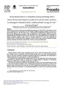
1. Introduction Introduced in July 2012, Japan’s feed-in tariff (FIT) policy was famously generous and triggered a surge in solar investment in the country. As photovoltaic (PV) installation density increases, more systems suffer from various failures. According to the failure reports, hot-spot heating accounts for a large proportion [1]. Hot-spot heating occurs when, due to some anomaly, such as shadows on cells, the reduced short-circuit current of affected cells becomes lower than the operating current of the module. This will force affected cells into a reverse bias condition, acting as an internal load, dissipating the power generated by other cells in the form of heat [2]. Figure 1 illustrates an infrared (IR) image of a hot-spot cell. Due to the poor thermal conductivities of cell encapsulation materials, temperatures of 100 ◦ C are easily attained. Such temperatures degrade the optical and mechanical properties of encapsulation material, reducing array performance, and operating lifetime [3]. In severe cases, the melting of interconnections can lead to total failure of the array [4]. Currently, bypass diodes are inserted in antiparallel with the PV cells to counteract the detrimental effect of shading. However, hot-spot heating may still occur even if bypass diodes are built-in. Due to crystal defects, some PV cells may exhibit a large reverse current, even before reaching the breakdown voltage [5–7]. Most of the recent methods of hot-spot inspection are based on I-V characteristics and temperature, and these methods are hard to locate hot-spot cells in assembled modules. Besides, it has been pointed out that it is important to classify reverse characteristic of each cell to determine the worst case with respect to the hot-spot heating [8–11]. Furthermore, compliance with International Electrotechnical Commission (IEC) and/or Underwriters Laboratories (UL) standards only requires 8–10 unit samples during hot-spot testing. The samples used for compliance testing are not representative of the typical Energies 2017, 10, 230; doi:10.3390/en10020230
www.mdpi.com/journal/energies
Energies 2017, 10, 230 Energies 2017, 10, 230
2 of 14
2 of 14
8–10 unit samples during hot-spot testing. The samples used for compliance testing are not product coming off the production line. Based on these considerations, our lab is striving to develop a representative of the typical product coming off the production line. Based on these considerations, new hot-spot inspection method which enables us to determine the hot-spot susceptibility of each cell our lab is striving to develop a new hot-spot inspection method which enables us to determine the in all modules coming offofof thecell production line. coming off of the production line. hot-spot susceptibility each in all modules
(a)
(b)
Figure 1. Infrared (IR) image of a hot-spot cell: (a) Hot-spot in a photovoltaic (PV) module caused by Figure 1. Infrared (IR) image of a hot-spot cell: (a) Hot-spot in a photovoltaic (PV) module caused crystal defects. The operating temperature at the hot-spot is 78.3 °C versus 45 °C of the rest of the by crystal defects. The operating temperature at the hot-spot is 78.3 ◦ C versus 45 ◦ C of the rest of module, which represents a temperature difference of 33.3 °C; (b) Temperature distribution of the the module, which represents a temperature difference of 33.3 ◦ C; (b) Temperature distribution of the hot-spot from P1 to P2, enormous power dissipation occurring in a relatively small area results in hot-spot from P1 to P2, enormous power dissipation occurring in a relatively small area results in hot-spots, which in turn leads to destructive effects, such as cell or glass cracking, melting of solder, hot-spots, which in turn leads to destructive effects, such as cell or glass cracking, melting of solder, or or degradation of the solar cell. degradation of the solar cell.
To achieve this goal, authors previously investigated the hot-spot heating caused by crystal defects and developed a voltage-based hot-spot detection the form of a projector To achieve this goal, authors previously investigated themethod hot-spotinheating caused by crystalwhich defects enables identification of defective cells. This method can eliminate the modules with defective cells and developed a voltage-based hot-spot detection method in the form of a projector which enables due to voltage ratio before they aremethod assembled into a system which will hopefully improve the to identification of defective cells. This can eliminate the modules with defective cells due reliability of PV system. However, crystal defects may also appear in normal cells after installation voltage ratio before they are assembled into a system which will hopefully improve the reliability of to various factors. Apparently, it is unrealistic to in diagnose modules by disassembling them PVdue system. However, crystal defects may also appear normalthe cells after installation due to various respectively. Aiming to avoid this problem and further confirm the practicability of the voltage-based factors. Apparently, it is unrealistic to diagnose the modules by disassembling them respectively. hot-spot detection method, we conducted several real field experiments for the PV string. The Aiming to avoid this problem and further confirm the practicability of the voltage-based hot-spot experimental process and results will be presented in this paper. detection method, we conducted several real field experiments for the PV string. The experimental process and results will be presented in this paper. 2. Theoretical Background
2. Theoretical Background Before presenting the details of the present study, it will be useful to review the general background associated with cell hot-spot heating. Crystal defects degrade the electrical Before presenting the details of the present study, it will be useful to review the general characteristics of p-n junctions, and, under reverse bias, can act as sites for premature avalanche or background associated with cell hot-spot heating. Crystal defects degrade the electrical characteristics Zener breakdown by locally enhancing the electric field. The resulting non-uniform current densities of p-n junctions, and, under reverse bias, can act as sites for premature avalanche or Zener produce hot-spots [3]. breakdown locally enhancing thewe electric field.a The non-uniform currentofdensities As a by representative example, prepared solarresulting PV module with the purpose accessingproduce each hot-spots [3].cells. Figure 2 indicates the reverse leakage current as discrete cells were reverse biased by one of the As a representative we prepared a solar PVcells module withdefects the purpose accessing each a power supply of 10 Vexample, in a darkened room. The normal without exhibit of a small reverse onecurrent. of the cells. Figure 2defective indicatescells, the reverse current as discrete cells were reverse biased by a Conversely, with a leakage high possibility hot-spot heating arising, consequently power supply 10 V in a darkened normalthe cells without defects exhibit small reverse present largeof reverse leakage current.room. FigureThe 3 declares reverse I-V curve of the cellsaindividually. current. defective cells, with high possibility arising, consequently As canConversely, be clearly observed in Figure 3, the acurrent of the defecthot-spot cells hasheating a linear relationship with the present large leakage current. Figure 3 declares thedemonstrate reverse I-V severe curve of the cells individually. reverse loadreverse voltage. The cells numbered 6, 24, 26 and 34 reverse current on the properties. In other words,3,once a solar cell likedefect No. 6 is reverse any abnormality, As electrical can be clearly observed in Figure the current of the cells has abiased linearby relationship with the reverse load voltage. The cells numbered 6, 24, 26 and 34 demonstrate severe reverse current on the electrical properties. In other words, once a solar cell like No. 6 is reverse biased by any abnormality, its
Energies 2017, 10, 230
3 of 14
Energies 2017, Energies 2017, 10, 10, 230230 Energies 2017, 10, 230 small reverse shunt resistance
3 of314 of 14
of 14 negates the effect of the bypass diode. The thermal images of3defective
small reverse shuntresistance resistancenegates negates the the effect effect of of of its its small reverse shunt of the the bypass bypass diode. diode.The Thethermal thermalimages images cells are presented inare Figure 4. in Figure defective cells presented 4. its small reverse resistance negates the effect of the bypass diode. The thermal images of defective cells are shunt presented in Figure 4.
defective cells are presented in Figure 4.
Figure 2. The current value in each cell energized at −10 V in dark conditions. It can be observed that
Figure 2.No. TheNo. current value in each cell energized at −10 V in dark conditions. It can be observed that No. 26value and No. 34 cells currents. Figure 6, 2. The24, current in each celldemonstrate energized atsevere −10 Vreverse in darkleakage conditions. It can be observed that No. 6,Figure No. 24, No. 26 and No. 34 cells demonstrate severe reverse leakage currents. 2. The current value in each cell energized at −10 V in dark conditions. It can be observed that No. 6, No. 24, No. 26 and No. 34 cells demonstrate severe reverse leakage currents. No. 6, No. 24, No. 26 and No. 34 cells demonstrate severe reverse leakage currents.
Figure 3. Reverse bias I-V characteristics of different cells belonging to the test module in dark conditions. The great dispersion in second quadrant behavior is notorious.
Figure 3. Reverse bias I-V characteristics of different cells belonging to the test module in dark
Figure 3. Reverse bias I-VI-Vcharacteristics of differentcells cells belonging module in dark Figure 3. Reverse bias characteristics of different to to thethe testtest module in dark conditions. The great dispersion in second quadrant behaviorbelonging is notorious. conditions. TheThe great dispersion ininsecond behaviorisisnotorious. notorious. conditions. great dispersion secondquadrant quadrant behavior
Figure 4. IR images of fully shaded defective cells. It can be observed that hot-spots tend to occur near the edge of defective cells.
Figure 5 images is the reverse model of a crystalline silicon solar cell. current flows through Figure 4. IR of fullybias shaded defective cells. It can be observed thatThe hot-spots tend to occur nearthe reverse solar cell can be expressed as:cells. Figure 4.images IR defective images ofcells. fully shaded defective cells. It that hot-spots tendtend to occur near near Figure IRbiased of fully shaded defective It can canbe beobserved observed that hot-spots to occur the4.edge of the edge of defective cells. the edge of defective cells. Figure 5 is the reverse bias model of a crystalline silicon solar cell. The current flows through the Figure 5 issolar the reverse model of aas: crystalline silicon solar cell. The current flows through the reverse biased cell canbias be expressed Figure is thesolar reverse biasbemodel of a crystalline silicon solar cell. The current flows through the reverse 5biased cell can expressed as:
reverse biased solar cell can be expressed as: Irev = IR + Ish = IR +
VR − Irev Rs V − Irev Rs I0 Rsh VR , Irev = I0 + R Irev = + Rsh Rsh Rsh + Rs Rsh + Rs
(1)
Energies 2017, 10, 230
4 of 14
Energies 2017, 10, 230
4 of 14
=
+
=
+
,
=
+
=
+
(1)
Here,IIrev thereverse reversecurrent currentof ofthe thesolar solarcell cell energized energized at at reverse reverse voltage V VRR,,IIRRisisthe theleakage leakage Here, revisisthe current of diode, and R is the shunt resistance which is process-induced, caused by grown-in defects current of diode, and Rshshis the shunt resistance which is process-induced, caused by grown-in defects ofthe thematerial. material.Either Eitherthe thesaturation saturationcurrent current of of silicon silicon diode diode II00increases increasesor or RRshshdecreases, decreases,the thereverse reverse of currentIIrevrevincreases increases[5]. [5]. current
Rs IR
Ish
-
Rsh
+
VR
Irev Figure 5. The reverse bias model of a crystalline silicon solar cell. Figure 5. The reverse bias model of a crystalline silicon solar cell.
As a microcosmic explanation, the existence of a partially crystal defect region, on the surface or a microcosmic explanation, theand existence of a partially crystal defect region, on the(electrons surface or insideAs the PV cells, abates the lifetime accelerates the recombination rate of carriers inside the PV cells,these abates the lifetime accelerates recombination of soft carriers (electrons and and holes) inside regions. Shortand carrier lifetimethe is more prone to rate cause breakdown even holes) inside these regions. Short carrier lifetime is more prone to cause soft breakdown even under under low voltage. Generally, the presence of a high recombination rate has two origins [12–14]. The low is voltage. Generally, presence of on a high rate has origins [12–14]. Thewhich first is first the production ofthe crystal defects the recombination surface of the solar cell two during manufacturing, the production of crystal defects on the surface of the solar cell during manufacturing, which results in results in high carrier recombination at the surface, another origin is when a carrier is trapped and high carrier recombination at the surface, another origin is when a carrier is trapped and recombines recombines in a crystal defect lattice within the semiconductor. For explanation purposes, the first in a can crystal defect lattice within theequations: semiconductor. For explanation purposes, the first case can be case be expressed by following expressed by following equations: = , = , = (2) / ( ) pn −) n2i / ( 1 1 Usur f = , Sp = , Sn = (2) 1/S p (n(1/cm + n13));+Sp1/S τ p Vp Nt τn Vn Nt(cm/s); τp and τn ) andn (SPn + areP1surface recombination velocity Here, ni is intrinsic density are hole and electron lifetime (s); vp and vn are hole and electron thermal velocity (cm/s); Nt is trap 3 S and S are surface recombination velocity (cm/s); τ and Here, ni 3is); intrinsic (1/cm p n p density (1/cm p1 and ndensity 1 are hole and ); electron density when energy level Et of the recombination τ are hole and electron lifetime (s); v and v are hole and electron thermal velocity (cm/s); N is trap n p n t center and Fermi level Ef are matched. The other case can be explained by Equation (3): 3 density (1/cm ); p1 and n1 are hole and electron density when energy level Et of the recombination − center and Fermi level Ef are matched. The = other case can be explained by Equation (3): (3) τ ( + )+τ ( + ) pn − n2i the reverse leakage current JR is given by Considering the theoretical formula for recombination, USRH = (3) τ p (nthe + ngeneration P1 ) JG produced by recombination 1 ) + τn ( P + the sum of the diode saturation current JO and current of the carriers. It is described as Equation (4): Considering the theoretical formula for recombination, the reverse leakage current JR is given by = JO and + ,the generation = (− )dcurrent JG produced by recombination (4) the sum of the diode saturation current of the carriers. It is described as Equation (4): U means total recombination rate (sum of Usurf and USRH) that occurs in cells. According to Z τn) is shortened by crystal defects, the Equations (1)–(3), when the carrier lifetime (τp and J = J + J , J = q(−U )dx in the reverse direction JR raises. (4) R leakage O G current G recombination rate U increases and the component Figure 6 is the equivalent circuit of a solar module. IA is the short circuit current of shaded cell U means (sumofof USRHB. ) that occurs in cells. to surf and the short circuitrate current theUcell of cluster Figure 6a shows the According case without in cluster A, andtotal IB is recombination Equations (1)–(3), when the carrier lifetime (τ and τ ) is shortened by crystal defects, the recombination p ipv flows n shadow, IA = IB and the module output current through cluster A and B. The bypass diodes rate U increases and the leakage current component in the reverse directionof JRthe raises. are all OFF. When partial shadows are added in cluster A, the characteristics respective clusters Figure 6 is the equivalent circuit of a solar module. I is the short circuit current of shaded cell in A are different, and IA < IB. In Figure 6b, when the hot-spot cell is shaded, its small shunt resistance cluster A, and I is the short circuit current of the cell of cluster B. Figure 6a shows the case without B of the bypass diode, the output current ipv of the solar module is smaller than IA, negates the effect shadow, I = I and the as module ipv flowsThe through cluster A and B.isThe bypass diodes A B and the same operation in theoutput Figurecurrent 6a is obtained. operation efficiency decreased and a are all OFF. When partial shadows are added in cluster A, the characteristics of the respective hot-spot arises. When the normal cell is shaded as in Figure 6c, due to its large reverseclusters shunt are different, and IA