Wcomp: Rapid Application Development Toolkit for Wearable computer based on Java* Daniel Cheung, J6rBme Fuchet, Florent Grillon, Gabriel Jouli6 Universitd de Nice Sophia Antipolis, Ecole Superiewe en Sciences Informatiques 930 route des Colles, 06903 Sophia Antipolis cedex
[email protected].;
[email protected];
[email protected],
[email protected]
-
Abstract Afrer apresenfation of what lies behind the terms Wearable Computing (Wcomp), thispaperfocwes on a newly developed Wcomp approach. It is bawd on a Rapid Application Development (R4D) toolkit used in order to make the creation of Java applications for wearable computer earier. This approach allows Wcomp to be easily and rapidly set up. The WO key elements of this paper are the BeonBox (rhe RAD toolkit) and the use of the BeanBox components i.e. the Sofmare Development Kit (SDK). For the applications to be context-aware, special sofrwme/hardware components, able to communicate with 12C hardware sensors, were added to the SDK. This classical sofiare architechrre guarantees the reusabiliq of basic components and underlines the relevance of this approach for the development of applications. These are consequently an assembly of functional hardware and sofiare units. At the end of this paper, WO aamples of quickly-built applications are described. Keywords: Wearable Computer, Context-aware Computing, Human Computer Interaction, Component Oriented Programming.
J.-Y.Tigli Universitt de Nice Sophia Antipolis, 13s Laboratory C N R S UMR 6070 930 route des Colles, 06903 Sophia Antipolis cedex
[email protected] concem office computers any longer, mobile systems are more and more involved, and this is a real transition In fact mobile systems often reproduce the functionalities of office computers (PDA) or are limited to specific tasks such as telecommunication (mobile phone). However the mobility of the user offers prospects which largely exceed the simple possibility of transporting a computer for traditional or dedicated tasks. It also implies other uses still to be discovered. For instance, it could adapt the specific needs of the mobile user following the latter's environment. Witbin the framework of the European project Zwear [3], a paper entitled "Futuristic Application Environment" was published on this topic. It rigorously analyzed (the components used, interaction diagrams and sequences) no less than ten scenarios of futuristic applications of mobile computers. These mobile information processing systems are referred to under the generic word wearable computer [SI, [l]. Wearable computers must then develop new features increasing the capabilities of the "classical" computers to perceive their environment. A wearable computer must take into account: the state of the environment and the resources still available (energy consumption for example).
1 Introduction Wcomp is described in five parts. First, we have to explain what is lying behind the terms Wearable Computing. This is what we will deal with in the next paragraph. Then, we will describe the Rapid Application Development (RAD) notion which is the key point of our contribution. This allows Wearable Computing to be easily and rapidly set up. Tbird stands the BeanBox and its components description i.e. the software development kit (SDK). To deal with the environment awareness computing, we will describe in the 3d chapter special softwarehardwarecomponents such as 1% [5] hardware sensors and their representation in the BeanBox. Finally we will explain three sample applications built following our approach. 1.1
Wearable computer
In the first part of this paper, we present the main features and the specificities of a Wcomp application. The information processing systems do not simply * 0-7803-7952-7/03/$17.00
0 2003 IEEE.
the user's state and thus his activity and the way be uses the mobile system (for example, if the user is waking or standing or sitting). its physical environment and should then adapt its activity to the local context (the background noise for example). other surrounding devices and it must be able to communicate with them (with a cellular network or remote computer for example). Thus, in order to develop Wcomp applications rapidly, we need to plug easily different sensors (GPS, digital compass, sensor of light or pressure sensor) and to be able to use them in an open softwarehardware architecture, one providing a visual style of programming.
4198
Authorized licensed use limited to: UR Sophia Antipolis. Downloaded on December 8, 2009 at 13:56 from IEEE Xplore. Restrictions apply.
2 RAD for Wearable Computer In the second part, we describe the approach used to deal with such requirements. We propose a component-oriented environment based on Java, which allows any advanced user to develop a Wcomp application through three steps: Plugging new hardware devices. Designing s o h a r e components for application. Assembling and configuring these s o h a r e components. 2.1
The BeanBox
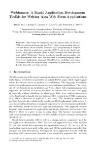
To put this Rapid Application Development (RAD) for Wcomp in a concrete form, we have written a complete development environment called JavaBeans Application Development Platform (ADP) dedicated to Java advanced programmers as well as people who have some notions of visual object programming and who have never programmed in Java (see Figure 1). Only with a few mouse clicks and within a few minutes, we can create a running application and then generate the binary code which can be executed either on a desktop computer or on a PDA. Our iirst main contribution i.e. a visual integrated development environment will be dealt with in the next paragraphs.
BeanBuilder or JavaBeans programming extensions in bigger Integrated Development Environment) only let the user compose test application into a graphical container or just propose a graphical view of a complete but superficial interactive graphical user interface (CUI).
We propose an extension of this GUI builder form by adding functional (not necessary graphical) components to the graphical application builder container. The idea is to set everything graphically. Furthermore, some ldnd of intelligence has been added to the builder container so that ADP computes all the obvious tasks for the user. The user's attention is required only &en conflicts appear when linking two JavaBeans together. Linking two JavaBeans is a semantic action from the user. If, when drawing an arrow from one JavaBean to another, more than one interpretation is possible, ADP asks the user to choose between the different solutions. This lets the user define the global semantic aspect of the final application. ADP offers the user a catalog of JavaBeans components extracted directly from a Java ARchive (JAR) file. A JAR file can be bought, downloaded from the Internet or written by the user. In this case, if the user wants to write JavaBeans from scratch, he may use special Java code wizards to write in Java easily (see 2.1.3).
We will first define the objects the user can interact with, they are called JavaBeans. Then, building an application will he made clear by the use of an example and finally the extra features of the platform will be described.
E Listener
F Listener
Figure 2. JavaBean mechanism.
Figure I. JavaBeans Application Development Platform.
A JavaBean is a Java object capable of emitting and receiving from other JavaBeans special objects called events. For that pwose, Event SourcdLisrener design puffem has been used A JavaBean ('B' for instance) that wants to receive events of type ' Gfrom a JavaBeans 'A' must subscribe to it as listener of 'G' as in Figure 2. This semantic action is represented with a blue arrow in the development environment (see Figure 4).
Fl
Graphical manageable objects: JavaBeans When launching the development environment, the user interacts with graphical components called JavaBeans. These JavaBeans symbolize functional or graphical blocks which the user will link together (such as Leg0 bricks) to build an application. Before going further, we will explain in detail what a JavaBean is. 2.1.1
First, ADP, the development enviromnen~is an adaptation of the famous BeanBox[2] which has been completely rewritten in order to enable a more intuitive grapbical approach of programming language. Standard BeanBoxes (even the last one &om S U N called
grapbical
Figure 3. Functional JavaBean vs. Grapbical JavaBean. As in Figure 3, JavaBeans can be either graphical (inteructive view) i.e. displayed on screen using gadgets
of Windows' graphical user interface (GUI) (such as buttons or scrollhars) or just functional (aperutionul 4199
Authorized licensed use limited to: UR Sophia Antipolis. Downloaded on December 8, 2009 at 13:56 from IEEE Xplore. Restrictions apply.
view) filtering values carried in events for instance. Graphical JavaBeans keep their graphical view on ADP's JavaBeans container called the design panel whereas the others are just wrapped into a symbolic label on the screen to be manipulated. Graphical manipulation consists in drag&drop, cut&paste or resizing and deleting JavaBeans as well as drawing events. ADP puts handles represented by red circles (see Figure 4) at the user's disposal. Multiple events can be drawn out of a single red circle. 2.1.2
Application designing example
Figure 4. A chain of JavaBeans A JavaBean stands as an actor on the ADP container. An application can also be considered as a chain of JavaBeans. In Figure 4, we have at the top of the chain a JavaBean called Pulser which sends every half-second an 'Action Event' to the Counter. It bas been previously registered to the Pulser as an Action Event listener; graphically, the user had previously drawn a line &om a red circle around the Pulser up to a Counter's red circle. ADP did not ask anytlllng to the user for the choice of the event was obvious (see Figure 5 , receivable and throwable events are described for each JavaBean).
The Counter is designed to receive Action Events and tn throw Property Change Events. When an Action Event is received, Counter increases its internal value by one (modulo two in this example) and sends the new value to its Property Change Event listeners.
Action Event
Properly Change Event .................I ,...............
TIFF] Functional
Functional
Graphical
Am0nErmtlMC.n
Figure 5. A chain of JavaBeans description. Each JavaBean previously described has a certain behavior. But this bebavior can be tuned thanks to the notion of athihutes or properties of a JavaBean. Therefore, a JavaBean behavior is not predefined and can be 'oriented' by the user afterwards. But once set, those athihutes cannot be dynamically changed by the final application. The only way to communicate between different JavaBeans is by event exchange. Indeed, a property panel is available in ADP for each JavaBean. These properties can he modified by the user. How can different JavaBeans be linked graphically together by events? A JavaBean is characterized hy a set of events that can be sent or received as in Figure 5. When linking two JavaBeans, a high level in@ospection mechanism Written in Java draws up a list of compatihle events that can be used in a drop-down menu The Java introspection mechanism called Java reflection is a particular dynamic scanner of objects. Tbis is a very interesting functionality which exists only in very high object-oriented programming languages.
Finally, the Label, the last JavaBean in the chain, receives the new value and therefore updates its graphical view with the new number. We have just described a binary counter. ,
The introspection mechanism is used to describe JavaBeans to the user, just by selecting one with the mouse. Thus, the user does not have to read documentation nor write any documentation when he decides to write a JavaBean himself. A suppolt class called 'Beanlnfo class' [IO] can be added afterwards to specify more precise details on a JavaBean (icons or event description).
Besides this simple example, we can easily build much more complex applications dealing with bardware sensors, software filters and user graphical interactions for instance. And as one might think. it needs neither more time nor effort to build it. But one needs to have the required JavaBeans.
Finally, the user draws its application into a special window called the design panel. The application is then translated in XML. This defines the persirtence ability of the application. We have developed a compiler which transforms X M L code into Java code which allows the user to generate an optimized application.
A complete set of JavaBeans corresponding to I2C hardware devices (mainly sensors) has been written (see 2.2). Moreover, paphical interactive (special scrollhars, progress bars, image viewers, zommers and scrollers) and even f u n c t i o ~ l(such as Kalman filters or adders) JavaBeans packages have been developed and are ready for use.
Moreover the structure can generate new JavaBeans (&om a JavaBeans wiring) whose inputs and outputs could be defined by the user via special IDEbuilt-in JavaBeans. 2.1.3
Extended features
The focus was on how to build an application giving pre-built JavaBeans packages. In the following section, we will i n t d u c e JavaBean code wizards. These are ADP inner-applications which ease the user's work It offers the user a way to write new JavaBeans or new Events without spending hours writing complex patterns of code. 4200
Authorized licensed use limited to: UR Sophia Antipolis. Downloaded on December 8, 2009 at 13:56 from IEEE Xplore. Restrictions apply.
ilEvmt
~
j
im Event
:Amibuter ~
-
.
...
:
1 :: 01Event
op Event
I"
Figure 6. JavaBeans characteristics A JavaBean is characterized by properties, input and output events (see Figure 6). When the user wants to create a new JavaBean, a window opens to list different properties and events characterizing the new JavaBean. Afler a few clicks and typed names, the software generates the pattem code and proposes the user to add the 'core' code i.e. the code telling the JavaBean what to do when an event occurs. Then, the new code can be compiled, stored in a JAR file and dynamically loaded into the design panel.
This new JavaBean might need a new Event. We have to know that an event is only characterized by attributes. ADP asks the user for the attributes to he included into the new event as well as the name of this event. Then, it generates the necessary Java source file and binary classes that can he used immediately. A verification mechanism is continuously running checking event existence and amihute and event conflicts using the introspection mechanism. This decreases the number of mistakes and allows the user to focus on the application's semantics and not its source code (the ADP guarantees that the code is optimized and correct). A portabilityfeature has been set up. It allows the user to port (i.e. to install and run) its application to other platforms i.e. embedded devices. A class checking inner-application has been added to ADP to perform this task. It scans the Java code to see if it can be projected into the embedded system fiwed with a virtual machine with fewer resources. A pre-verifier task has been implemented in order to modify binary class files to support very light virtual machines such as the KVM [9]. The porting inner-application draws up a list of devices, lets the user choose a special device and then builds a JAR file containing the embedded application. 2.2
communication between high-level components (JavaBeans) and low-level devices (sensors) (see below).
r
I I
h lcvd Hzrware COmpOSICnl
HighlevelHlwzre component 1 BeNCf
1
Figure 7. Bean of Device 2.2.1
U C device example
Our generic hardware devices have been developed and validated using IT [3]. This standard has been chosen because it is low cost, low power, and very easy to use. So it is really adapted for prototyping. Each hardware device is a Remote Procedure Call (RPC) server connected to a RPC client JavaBeans. This RPC protocol is designed to carry sofhvare JavaBean events through I T bus down to hardware device. A micro-kemel has been implemented so that one can send orders either on the serial port or on the 12C port (see Figure 8). We have designed a system capable of managing synchronously asynchronous messages. No resource conflict must occur. The pan of the kemel which receives orders must be distinct from the one which executes the task. Rcgtstw
lnterupts mannagel
Trap manager
Code scheduler
Bean of Device
We can now focus on the second main contribution of our approach i.e. generic hardware devices automatically interfaced with their own software component. In other words, each hardware component is represented by a JavaBean. This is the reason why we use the term of 'Bean of Device'. But how do these devices communicate to each other? The hardware structure communication is based on a simplified OS1 network protocol (see Figure 7). This approach allows us to use different complex devices. These devices can be used as servers using different type of communication support: 1% bus, Bluetooth, Java RMI network [11][6]). In our approach, we used I% bus communication. A microcontroller contains a micro-kemel assuring the
I .b"li ..
I
Figure 8. Embedded kernel structure. Thus, our kernel is a simple RPC client standing for a router between I2C and Serial bus. A user-code can be downloaded thanks to a special order. This user-code can then take the complete control of the device. But a watchdog timer is continuously running thus securing the main purpose of the device: routing orders.
3 Wcomp examples Several sample applications were built to test the JavaBeans ADP. We propose two examples: the context adaptive text editor and the panoramic image viewer.
4201
Authorized licensed use limited to: UR Sophia Antipolis. Downloaded on December 8, 2009 at 13:56 from IEEE Xplore. Restrictions apply.
3.1
Context adaptive editor
This sample application is a text editor which can open and save text files. Its particularity is that it is context-sensitive.
Figure 12. Context adaptive editor JavaBeans wiring. Finally, we are not going to detail the used JavaBeans, which would he only accurate for people who want to build the application using our s o h a r e environment.
3.2
Panorama application
The Panorama Application has been written to allow people to see panoramic pictures. It must be executed on a PDA fitted with a head mounted display (HMD). The PDA's screen VGA output is connected to HMD which projects the image to the user. Figure 9. Hardware structure. Its menu and text as well as the background colors of the application change according to the variations of light: the darker the environment, the lighter and the more contrasted the application interface. An I2C light sensor has been used to obtain this behavior.
An electronic compass connected to the application is put on the HMI). It gives the angle position of the user's head. Giving that, the software localizes the zone of the panoramic image to be displayed (see Figure 13).
\
s
s
I, I,
t
Figure 13. Head position and picture display zone Figure IO. Color adaptation.
lF*-p
The application also reacts following the user's distance ffom the screen. The closer the user, the smaller the fonts. For that purpose, an I2C Ultrasonic distance sensor has been used.
. i - 2'
J d d position
0
1.
:
Figure 14. Hand position and zoom factor. t Bistance to the user
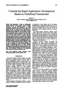
In this application, a JavaBean has been written to represent the famous Kahnan filter (see the two top left and right JavaBeans in Figure 15).
Figure 11. Font sue adaptation,
To build the application, we needed 17 functional and 5 graphical JavaBeans (see Figure 12).
4202
Authorized licensed use limited to: UR Sophia Antipolis. Downloaded on December 8, 2009 at 13:56 from IEEE Xplore. Restrictions apply.
~
2003), World Conference on Open Learning Distance Education, June I -June 5,2003 - Hong Kong.
Philips, “IZC Specifications”, semiconducton.philips.comhusediZc.
[S]
-
http://www.
[6] I. Pi”, “Bluetooth Development Kits”, Technical Report 37882T, Helsinki University of Technology, Department of Computer Science.
’.
[7] A. Ressouche, V. Roy, 1.-Y. Tigli and D. Cheung, “SAS architecture: Verification Oriented Formal Modeling of Concrete Critical Systems”, to appear in Intemational Conference on Systems, Man and Cybemectics, Washington, October, 2003.
Figure 15. Panorama JavaBeans wiring
4 Conclusions In the first part, the stress was laid on the d e f ~ t i o n of wearable computing, a technique we managed to develop. We built the Rapid Application Development software so that the application might be error-i?ee and easily and quickly programmed. The examples in the third part were instrumental in underlining the advantages of such a technique.
Nevertheless, a problem appears when one wants to build more complex applications and to reuse previous code. When a new component is added to an already built complex application, the behavior of this application can be altered because the new component disturbs the time structure. As a matter of fact, adding a component which needs a lot of CPU time to be executed entails that the other components of the application are deprived of this period of time. Thus, they cannot function properly. So, we have to program new inferactions between the existing and the newly created components. Some future works will be dedicated to avoiding such a drawback We created a sofiware architecture based on a new kind of components called “behavioral components” [lo] in order to improve and control interactions between the different reusable components.
[8] T. Stamer, ‘The Challenges of Wearable Computing”, IEEE Micro, 0272-1732/01/$10.00 Q 2001 IEEE, July/August 2001. [9] Sun Microsystems Inc., “Java 2 Platform Micro Edition (JZME) Technology for Creating Mobile Devices”, May 2000. [IO] Sun Microsystems Inc., “JavaBeans”, JavaBeons
API Specifratians, August 1997. [ 1I] 1. Waldo, “JINI Architecture Overview”, available at http://java.cun.com/product/jini/whitepapers.
References [I] Camegie Mellon University, Institute for Complex Engineered Systems, “Family Tree of CMU Wearable http://www.cs.cmu.edu/afs/cs.cmu.Edu/ Computer”, project /vuman/mhome.html. [2] M. Johnson, “The B d o x ” , Sun’sJovaBeans test container, http://www.javaworld.com/jw-09-1997/jw09-beanhx.html, September 1997. [3] S. Lalis, “A Runtime for Adaptive and Extensible Wireless Wearables”, 2WEAR European project, disappearing Computing Initiative, IST research program activity, web http:/huww.disapparingcomputer.net /projects/ 2WEAR.hhnl. [4] S. Lavirotte, and 1.-Y. Tigli, “Mobility m eleaming context”, Distributing Infomotion Dependin 3 on Geographical Lacalizatian and User Profile, 21 International Conference on Data Engineering (ICDE
4203
Authorized licensed use limited to: UR Sophia Antipolis. Downloaded on December 8, 2009 at 13:56 from IEEE Xplore. Restrictions apply.