Web-based Customer Management of Virtual Private Networks Raouf Boutaba1, Walfrey Ng. 2, and Alberto Leon-Garcia3 1
Department of Computer Science, University of Waterloo Waterloo, Ontario, N2L 3G1, Canada E-mail:
[email protected] 2
IBM Canada Ltd., 3600 Steeles Avenue East Markham, Ontario, L3R 9Z7, Canada Email:
[email protected] 3
Department of ECE, University of Toronto Toronto, Ontario, Canada, M5S 3G4 Email:
[email protected]
Abstract Virtual Private Network (VPN) is one of the major trends in the integrated broadband communications environment. Commonly, a network operator or a value added service provider offers VPN services to corporations that wish to tie together their geographically dispersed offices. Currently, the control and management of the VPN resources is mainly supported by the provider of the bearer telecommunication services and the VPN customers have no control over these resources. The increasing importance of the broadband communication infrastructure in corporate operations and transactions is stressing the requirement for a customizable configuration, operation and management of VPN services. First, this paper discusses the evolution of VPN environments towards customized VPN configurations and goal-driven management of these VPNs. VPN service characteristics and management requirements are analyzed. Then, this paper introduces the proposed customer management architecture satisfying these requirements. The architecture is based on the multi-level virtualization of network resources through the partitioning of resources in the provider’s shared communication infrastructure and the dynamic allocation of these resources to customers. A Web-based distributed approach is used for implementing the proposed customer management of VPNs. An ATM testbed is used to support different partitioning schemes providing VPN services with differing QoS requirements. Finally the proposal is applied to IP and ATM integration and customer monitoring of VPN resources.
Keywords: Virtual private network, resource partitioning, customer management, Web-based management.
1
1
Introduction
Virtual Private Network (VPN) aims at offering to a multi-site customer a flexible and costeffective transport service. Typical customers are large corporations that wish to connect their geographically separated offices through public networks. As opposed to leased-lines based private networks, the VPN service allows for a more efficient and flexible use of the common public network infrastructure so the provision of communication resources can be easily adjusted to the changing traffic requirements of customers. Resource sharing allows for a cost-effective communication infrastructure, however it poses the problem of ensuring communications privacy. Privacy in VPNs concerns both the characteristics of communications services, such as the addressing or routing schemes, and the integrity of the communications including data privacy and security. Therefore a VPN service instance is isolated from all other environments which share the common communication infrastructure. There are several methods for constructing VPNs resulting in a variety of VPN implementations. In general, these can be categorized into two main models: “peer” and “overlay” VPN models.
In the former, the network layer
forwarding path computation is done on a hop-by-hop basis like in traditional routed networks. In the latter VPN model, the intermediate link layer network is used as a “cut-through” to another edge node on the other side of a large cloud. Typical examples of overlay VPN models are ATM, Frame Relay, and tunneling implementations. Encryption techniques are also used to construct VPNs at all layers of the protocol stack and in particular at the transport and application layers. This paper starts with an overview of the different VPN models together with an analysis of the methods used to construct them.
The VPN service is commonly offered by a service provider to a number of service subscribers referred to as the “VPN customers” in this paper. The “VPN Provider” can be a public network provider or a third party, which uses bearer network facilities offered by one or several network
2
providers. In classical VPN environments, the provider of the bearer communications services manages the VPN resources, while VPN customers have no control over the resources allocated to them. The increasing importance of the broadband communication infrastructure in corporate operations and transactions is stressing the requirement for customizable configuration, operation and management of VPN services. This is typified by the need of VPN customers to control the resources they are paying for according to their corporate goals by implementing their own management strategies and security policies. Also achieving customer control will fasten the introduction of new communication services. This paper discusses the evolution of VPN environments in terms of the managerial roles of the actors involved in the provision of the VPN service. It describes the main administrative domains, VPN Provider and VPN Customer, the main operation and management functions in these domains, and the peer-to-peer contract-based interactions between these domains. The trend towards a customer goal-driven operation and management of customized VPN configurations is highlighted together with the faced technological and regulatory constraints.
To allow for a flexible and efficient operation and management of VPN resources in a multidomain environment and to respond to the customizable management requirement, the VNRM (Virtual Network Resource Management) architecture has been designed. The VNRM architecture is generic in that it applies, through customization, to all administrative domains involved in the VPN service. It is based on the virtual network (VN) concept introduced as a generalization of the VPN for supporting multi-levels virtualization of network resources. For example, root-network providers provide networking resources (root-VNs) to VPN providers, which are the customers of the network providers. In turn VPN providers provide a VPN service (a subset of the provider network resources, or VNs) to VPN customers. Such network virtualization and client/server relationship can involve as many levels as necessary and is motivated by the multiplication of value added service providers including network backbone
3
providers, network access providers, bandwidth wholesale providers, content providers and applications service providers. Ulimately, the purpose of a VN is to allow a “soft networking environment”. Soft networking environment means flexible resource capacity, configurable network topology, and programmable network operation and management architecture. Flexibility in resource capacity and configurability of network topology are exercised by the internal functionality of a provider VNRM system. Programmability in network operation and management functions is supported through the dynamic binding of the VN resources to any operation/management system of customer's choice with proper algorithms, mechanisms, and interfaces.
The configuration of VPNs and their customized management is effectively achieved through logical partitioning of MIBs. The MIBlet concept is used to provide abstract and selective views of the physical network resources allocated to VN customers. The abstract view hides the details of the resource interface that are not relevant to the customer’s VNRM. The selective view restricts the access of the customer’s VNRM system to those parts of the network resource allocated to this customer. To allow for flexible resource allocation schemes, and hence, a better network resources utilization, two types of Virtual Network Resources (VNRs) are defined: hard and soft. A hard VNR is created with a specified amount of capacity allocated. A soft VNR is created with no explicit amount of capacity allocated. Further amount of resource capacity is allocated dynamically on a demand basis up to a maximum amount. The capacity of a hard VNR may also be changed through management requests from the customer, which normally takes place with longer time scale. The concept of a soft VNR plays an important role for demandbased dynamic capacity management of VPNs. It leads, however, to competition among VPNs, and thus necessitates appropriate mechanisms for admission control and resource usage policing. In the VNRM architecture these mechanisms are provided in both management domains: A customer VNRM system, referred to as Customer Network Management Systems or CNRMS,
4
enforces its own control policies; and a provider VNRM system implements additional arbitration functions.
MIBlets and thereby VPNs result from the partitioning of the common underlying network resources (their MIB representations). In the frame of our ATM-based testbed, different partitioning schemes at the ATM port, VP and VC levels as well as bandwidth are supported to provide virtual network services with differing QoS requirements. Customer’s VPN operation and management functions are implemented through MIBlet controllers located at every network node involved in the customer’s VPN. MIBlet controllers enforce customers’ access control and resource usage policing strategies and are invoked to set up, monitor and control the customer’s connections. The capabilities of the proposed CNRMS architecture are demonstrated through applications including IP and ATM integration, and selective customer monitoring of VPNs.
The implementation of CNRMS is done in a distributed fashion to allow for an efficient operation and management of the VPN. This is achieved by means of downloadable customer’s control and management software. The latter is written in Java and hosted by a programmable controller at the level of each resource involved in the provision of the VPN. The programmable controller acts autonomously on behalf of the customer to monitor and control those parts of the resource allocated to the customer through the resource representation in the MIBlet. It manages the execution of management software using a script MIB and interacts with the MIBlet controller through a standard SNMP interface. The human operator/manager in the customer domain accesses the CNRMS through a Java-enabled Web browser. Several graphical user interfaces were defined to allow the human operator/manager to control VPN resources and download control software as well as management scripts to these resources. Operation and management applications are supported within a management server. The server implements the delegation of management tasks, in the form of mobile Java scripts, to programmable controllers in the VPN.
5
This distributed implementation of the VNRM system allows to reduce the traffic of management information in the network and to fasten the reaction to the occurrence of significant events at the level of the VPN resources. SNMP, Java and Web technologies were used to allow for openness and portability of VNRM systems and thereby customer management of VPN services.
This paper is structured as follows. Section 2 overviews the different types of VPNs and analyses the methods used to construct them. Section 3 studies the characteristics of the VPN service, analyses the requirement for customer management of VPN services. Section 4 introduces the generic customizable CNRMS architecture and the partitioning of network resources using MIBlets. Section 5 describes the Web-based design of the distributed CNRMS architecture. Section 6 discusses applications illustrating the utilization of CNRMS. Finally, section 7 concludes the paper and points out future research directions.
2
VPN Models
There are a myriad of definitions of Virtual Private Network (VPN) used in the networking community to describe a broad set of problems and solutions. In [1], Ferguson and al. define a VPN as a communications environment in which access is controlled to permit peer connections only within a defined community of interest. A VPN is constructed through some form of partitioning of a common underlying communications medium, where this underlying communications medium provides services to the network on a non-exclusive basis”.
A VPN service is primarily useful for organizations that wish to use public networks (MAN’s and WAN’s) to connect their various LAN’s for private purposes. This is typically the case of large corporations that need to connect a set of geographically separated offices while preserving the private character of their overall network. Therefore, the VPN concept has to respond to the two conflicting requirements:
6
1. Allow for a cost-effective communications infrastructure through resource sharing. Compared to the dedicated leased circuits approach, organizations reduce the cost of connecting geographically dispersed sites by establishing VPNs across a shared public network. 2. Allow for communications privacy. Although several organizations share a common communications infrastructure (public backbone network), they want their communications services to be within one closed environment isolated from all other environments that share the common underlying communication infrastructure.
VPN services are commonly offered by a value added service provider to a number of service subscribers referred to as the VPN customers. The VPN provider sets up the VPN connectivity for a customer using the services of multiple Public Network Operators (PNOs). The VPN provider may be a separate organization or it may be part of one of the PNOs. The advantage of the VPN provider as an intermediate level between the customer and the involved PNO(s) is that of one-stop shopping which provides a single interface to the customer for accepting requests, queries and complaints, and also to provide a single bill to the customer.
The initial target of the VPN concept was to successfully replace the leased lines-based private data networks and PBX interconnection. The evolution of VPN is motivated by the reduction of the high cost due to the dedication of certain equipment. Most of existing VPN services are based on conventional Public Switched Telephone Networks (PSTN) or on Public Switched Packet data Networks (PSPDN). Second generation VPNs use technologies such as ATM cross connect, and support semi-permanent pipes such as ATM end-to-end Virtual Path Connections (VPCs). The management services include configuration and static bandwidth management, in which bandwidth is not altered after VPC set up. New generation VPNs are evolving to support full
7
open network provisioning. They use B-ISDN based on switched ATM and IP routing capabilities as well as encryption techniques.
The methods to construct VPNs can be categorized into two main models: “peer” and “overlay” VPN models [1]. In the peer VPN model, the network layer forwarding path computation is done on a hop-by-hop basis. Traditional routed networks are typical examples of peer models, where each router in the network path is a peer with its next hop adjacencies. In the overlay VPN model, the intermediate link layer network is used as a “cut-through” to another edge node on the other side of a large cloud. Typical examples of overlay VPN models are ATM, Frame Relay, and tunneling implementations. The VPN architecture depends on the layer of the protocol suite that is used to implement the VPN service. Also, the complexity of implementation and maintenance of the VPN depend on the type of the targeted VPN as well as on scalability and security requirements. The remaining of this section overviews the different types of VPNs and presents their respective features.
2.1
Overlay VPN Models
Overlay VPN models are more naturally implemented at link-layer of protocol stack. A linklayer VPN attempts to provide a functionality similar to conventional private data networks while achieving economies of scale and operation through multiplexing (using virtual circuits instead of dedicated transmission paths). In this scenario, VPNs share a common switched public network infrastructure for connectivity (i.e., the same switching elements within the public network), while the VPNs have no visibility of one another. Usually, such infrastructure consists of Frame Relay or ATM network. The major advantage of utilizing virtual circuits in the public switched networks is their flexibility and cost-effectiveness. However, the disadvantage is the scaling limitation and the difficulty in configuration management.
8
Multi Protocol Over ATM [2] (MPOA) is an “overlay” model of constructing VPNs similar to the “cut-through” mechanisms where the switched ATM network enables egress nodes to be one “Layer-3” hop away from one another, using dynamically controlled edge-to-edge ATM Virtual Connections (VC’s). However, MPOA approach assumes a homogeneous ATM environment, and relies on external address resolution servers to support the ARP (Address Resolution Protocol).
Tunneling is one method of constructing VPNs by sending specific portions of network traffic across tunnels. It is considered as an overlay model. The most common mechanisms are GRE (Generic Routing Encapsulation) [3] tunneling between a source and destination router, router-torouter or host-to-host tunneling protocols such as L2TP [4] (Layer 2 Tunneling Protocol) and PPTP [5] (Point-to-Point Tunneling Protocol), and DVMRP [6] (Distance Vector Multicast Routing Protocol) tunnels.
2.2
Peer VPN Models
Controlled Route Leaking is one implementation of the peer VPN model. It consists of controlling route propagation to the point that only certain client networks receive routes for other networks which are within their own community of interest. The routes associated with a set of clients are filtered such that they are not announced to any other set of connected clients, and that all other non-VPN routes are not announced to the clients of the VPN. The controlled route leaking technique is considered to be prone to administrative errors, and admit an undue level of insecurity and network inflexibility. In addition, this technique does not possess the scaling properties desirable to allow the number of VPNs to grow beyond the bounds of a few hundreds, using today’s routing technologies. An alternative technique uses BGP communities attribute [7, 8] to control route propagation. This method is less prone to human misconfiguration and allows for a better scalability. It allows a VPN provider to “tag” BGP NLRI’s (Network Layer
9
Reachability Information) with a community attribute, such that configuration control allows route information to be propagated in accordance with a community profile. The BGP communities technique allows flexible construction of network layer VPNs by preventing VPN service subscribers to detect the fact that there are other subscribers to the service. However, it does not guarantee data privacy in the core of the service provider’s network (i.e., the portion of the network where traffic from multiple communities of interest share the infrastructure).
Multi-Protocol Label Switching [9] (MPLS) is an hybrid architecture which combines the use of network layer routing structures and per-packet switching, and the use of link-layer circuits and per-flow switching. In the case of IP over ATM, each ATM bearer link becomes visible as an IP link, and the ATM switches are augmented with IP routing functionality. The latter is used to select a transit path across the network, and those transit paths are marked with a sequence of locally defined forwarding path indicators or labels. A generic MPLS architecture for the support of VPN structures is that of a label switched common host network and a collection of VPN environments that use label-defined virtual circuits on an edge-to-edge basis across the MPLS environment. The label applied to a packet on ingress to the MPLS environment effectively determines the selection of the egress router, as the sequence of label switches defines an edge-toedge virtual path.
Indeed, MPLS itself and the direction of VPN support using MPLS
architecture are still under active research. So, this approach to support VPN is still somewhat speculative in nature.
2.3
Encryption-based VPNs
Encryption technologies are effective in providing the virtualization required for VPN connectivity, and can be deployed at almost any layer of the protocol stack. The implementation of VPNs at the transport and application layers is mostly based on the use of encryption services. Application layer encryption, for example, is the most pervasive method of constructing VPNs in
10
multiprotocol networks. Transport layer encryption aims at providing privacy and data integrity between two communicating applications. For this purpose the Transport Layer Security Protocol or TLS [10] is being defined within IETF (Internet Engineering Task Force). Network layer encryption is implemented according to two modes: the end-to-end mode where encryption is performed between participating hosts; and the tunnel mode where encryption is performed between intermediate routers. The first mode allows for a higher level of security, however implements VPN granularity at the level of the individual end system. The second mode is less secure in that it leaves the tunnel ingress and egress points vulnerable, since these points are logically part of the host network as well as being part of the unencrypted VPN network. In the Internet, the network layer encryption standard being defined within the IETF is IPSec (IP Security) [10]. Encryption at the link layer is supported by special encryption hardware generally vendor specific and hence poses interoperability problems in multi-vendor environments.
3
3.1
VPN Service Provision, Operation & Management
Current Practice
The VPN is mainly viewed from two distinct viewpoints: the VPN customer and the VPN provider. The VPN customer represents the closed user group of the VPN. It is responsible for negotiating the VPN services with the VPN provider. The negotiation includes the type of services required, the offered quality and the cost. If the VPN fails to provide the contracted quality of service, the customer complains to the VPN provider. The VPN provider is the party offering the VPN service to the VPN customer. Commonly, each VPN has one provider, which can be either a private company or a public network provider. The most important task of the VPN provider is to coordinate the various sub-networks over which the VPN is built and to make this inter-working transparent to the VPN customer. The VPN provider predicts the traffic generated by its customers and plans the capacity of its network resources. In case the VPN
11
service provider is the public network provider, then the VPN provider is also responsible for operating the network over which the VPN is implemented.
VPN provision may involve several levels of providers and customers. The visibility of network resources is not the same in these distinct administrative domains and the operation and management functions are not applied the same way. Efficient operation of the network necessitates the management of the available resources in order to maximize their utilization and to ensure the expected Quality of Service (QoS). The provision of VPN imposes further requirements on the management of network resources (physical and logical) which has to be performed in a cooperative way between VPN providers and VPN customers. The configuration of the VPN commonly leads to the reservation of a set of resources in order to accommodate the VPN traffic.
3.1.1. Operation and Management Functions The estimation of the traffic expected to be generated by the VPN users is a prerequisite to determine the transmission and switching capabilities needed to support the VPN operation. This estimation, often referred to as user traffic characterization, is initially used by the VPN customer to select which VPN service to subscribe to. It is then continuously adjusted to reflect the real utilization of the subscribed services (e.g., frequency and duration of service utilization) possibly leading to service re-negotiation. The VPN provider has also to continuously estimate the expected traffic to accommodate changing VPN customers needs. The provision of the VPN service consists of network resources reservation according to the specified performance and bandwidth requirements. The service may be of the following types: −
Fixed bandwidth is provided for the lifetime of a VPN;
12
−
Pre-booked bandwidth variations where the customer may specify in advance how the bandwidth reserved on a VPN should vary over time (throughout the working day for example);
−
Bandwidth on demand where the customer may change the bandwidth reserved on an already existing VPN.
To configure a VPN, the VPN provider takes into account the location of the VPN customer sites and the associated traffic needs as estimated in the traffic characterization phase. The VPN customers provide the VPN provider with a private addressing scheme (if applicable), an estimate of traffic requirements and the requested Grade of Service (GoS). Based on the previous information, the VPN provider plans his network by determining the type and amount of transmission and switching resources. The objective of the VPN provider is usually to minimize the amount of network resources in order to reduce the cost and hence maximize the revenue while satisfying the QoS contracted to VPN customers. VPN reconfigurations may also take place during the VPN lifetime to take into account changes of user-traffic requirements (e.g., servive upgrade); faults occurrence at the network level; QoS degradation; customer’s complaints; and others.
A continuous monitoring of the VPN customer traffic and the underlying network is performed by the VPN provider to ensure that the service is provided to customers according to the contracted QoS. The VPN customer computes statistics on the VPN service performance (e.g., the number of (un)successful accesses). The measured and the expected VPN performance are then compared which may lead, in case the VPN users are not satisfied with the experienced QoS, to issuing complaints to the VPN provider or to a re-negotiation of QoS parameters.
13
The VPN service can be used by VPN customers only. Therefore, access control mechanisms are required to protect VPN users/services from unauthorized access. Encryption mechanisms can be used to guarantee privacy and data integrity. These mechanisms are usually defined on a per closed user group (i.e. customer) basis. Accounting management uses the information collected by the VPN provider monitoring function in order to establish the service usage bills of the VPN customer.
3.1.2. Inter-domain VPN Management VPN end-to-end management requires interactions between VPN customer and VPN provider(s) management domains. These interactions are peer-to-peer, based on a client/server model, and mainly correspond to negotiating the VPN configuration and the VPN service provision according to the agreed contract. Contracts specify equipment rental and service-level agreements (SLA). During the lifetime of the VPN, the management domains interact to ensure proper operation of the VPN or to renegotiate their contracts. The customer is responsible for identifying the end points, the performance (delay, jitter, packet loss ratio), and the bandwidth (peak bandwidth and variations in bandwidth over time) requirements. According to traffic characteristics and grade of service agreed with the customer, the VPN Provider establishes the VPN with the negotiated QoS. In addition to the regular VPN, the customer may require exceptional traffic demands such as setting up high bandwidth calls at given times or changing backup schedule leading to changes in bandwidth requirements. The customer complaints to the provider whenever the offered QoS is below the negotiated one. The customer may also request for re-configuration of the VPN. Ultimately, VPN Provider management is required to provide a single interface to the customer for accepting requests, queries and complaints and also to provide a single bill to the customer. In case the VPN provider is a value added service provider distinct from the public network operator, the VPN provider determines which public network operators should be involved in the provision of the VPN. The VPN provider identifies the end points in
14
each public network domain, the performance and bandwidth requirements, and rents network resources from the involved public network operators. In turn network operators interact with each other to negotiate which network resources between their gateway nodes will be used for the VPN.
Service level agreement (SLA), mainly consisting of the traffic contract, is the basis for the peerto-peer negotiations involved in a VPN service provision. A traffic contract can be defined for every connection. It consists of connection traffic descriptors and QoS parameters. Each customer is expected to generate traffic that conforms to these parameters. The VPN service provider monitors the offered load and enforces the traffic contract. The VPN service provider is committed to meet the requested QoS, as long as the customer complies with the traffic contract. In addition to the traffic contract, a service contract, for example between the customer and the VPN provider, may include time intervals information for the connections (e.g., days of the week, times during the day, duration etc.) and which customer sites should be connected.
3.2
The requirement for customer management of VPN
In traditional VPN environments, the customer has the view of the configuration of its CPN (Customer Premises Network) and a view of the VPN resources dedicated to interconnect its sites. The customer is also aware of the capacity of these connections. The VPN provider has a view of the access and transit nodes (VPN switching/routing nodes in the public network domain) and the interconnection between them. If the VPN service provider is also the public network provider then it has also an explicit view of the physical configuration of its own network including the transit and access nodes constituting the public network as well as the links interconnecting these nodes.
15
In this traditional scenario, the VPN provider hides the network topology as far as the customer was not interested in the way the connections between the customer sites are realized. The main reason for that is the assumption that customers do not have the appropriate skills to control and manage the public network resources that are rented to them. In this case, the customer only controls its CPN including the equipment used to access the public network. The customer also performs the modifications in the CPN when requested (e.g., updates the route selection tables or the private addressing scheme, etc.). The VPN service provider, as a value added service provider, plays an intermediate role between the customers and the involved providers of bearer communication services. It operates the network links rented from the network providers and allocates the contracted bandwidth to customers. In this case, the VPN service provider has a limited access to the network infrastructure and performs management such as the reconfiguration of the links indirectly by requesting the appropriate network provider.
Currently, customers ranging from large to medium and small enterprises are relying more than ever on the networks to conduct their businesses. For that reason, they are either acquiring the appropriate management tools and qualified personnel to administrate and maintain their growing customer premises networks or outsourcing the management of their network resources to third parties. Moreover, customers are seeking to control and manage the VPN services they are subscribing to. There are several reasons for that. Above all is the possibility for customers to control and manage their VPNs according to their own policies reflecting their business goals. A VPN service provider cannot easily accommodate a large variety of service requirements of the various customers. Customers may have different traffic requirements (data, voice, and video) with different priority schemes and performance characteristics. They often require different levels of security. Another important reason for customers to control and manage their VPN is to perform the necessary partitioning of the VPN resources among the different end-users and applications they support, and to implement their own policing mechanisms. Last but not the least
16
is the ability of customers to introduce new communication services if they have full control over the resources allocated to them in the provider’s network nodes and hence the possibility to introduce their proper resource control algorithms. This trend has been recently strengthened by the emergence and wide acceptance of network programmability as the networking paradigm of the future.
Indeed, a large effort is currently spend in both academia and industry to open the core network infrastructure and facilitate its programmability by providing the appropriate application programming interfaces. Among the undergoing works on related issues, there are: the definition of open switching architectures [11], the specification of open signaling protocols [12], the development of programmable and active networks [13]. This trend will bring new challenges to the control and management of network resources. One of the most critical problems that need to be addressed is the shared control and management of the network resources between several domains, which may lead to conflicts. In general, the functions of each domain and the interactions between the different domains have to be re-engineered.
4
Customer Management of VPN Resources
This section briefly introduces the generic Virtual Network Resource Management (VNRM) Architecture designed in the Network Architecture Lab (NAL) at the University of Toronto for network customization [14]. The VNRM Architecture is based on the Virtual Network (VN) concept. The purpose of a Virtual Network (VN) is to allow a soft networking environment. Soft networking environment means flexible resource capacity, configurable network topology, and programmable network operation and management. A Virtual Network (VN) is defined as a collection of Virtual Network Resources. A virtual network resource is defined as a logical subset of a physical network resource such as transmission bandwidth, buffer queues, switch processing
17
power, address space, scheduling mechanism and so forth. This network resources virtualization can be generalized to create multiple VN layers through vertical spawning (see Figure 1). S ec o n d ary C u s to m er's NR MS C lien t/S erv er
VN
O p era tio n & M a n a g em en t
R ela tio n sh ip
P rim ary C u s to m er's & S ec o n d ary P ro v id er's V NR MS C lien t/S erv er
S p a w n in g O p era tio n & M a n a g em en t
VN VN
R ela tio n sh ip S p a w n in g
P rim ary P ro v id er's R oot-V NR MS
O p era tio n & M a n a g em en t
VN R oot V N
Figure 1: Domain-based VNRM systems
The generic VNRM architecture can be customized and applied to manage every VN layer and every sub-network in a network composition. However, for the sake of clarity the following discussion of system design is restricted to a limited number of client/server relationship levels between VN providers and VN customers, and therefore “VN” and “VPN” are used interchangeably in the remaining of the paper. Typically, a number of Network Providers will play the role of Root-VN providers. A VN service provider will play the role of the Primary VN customer (the secondary VN Provider). The VPN service provider aggregates the network resources of multiple Network Providers and provides a single stop shopping to VPN customers. A VPN customer is a secondary customer and is typically a private company with a number of geographically dispersed branches. It uses the VPN provider services to interconnect its branches.
In this paper emphasis lies on the Web-based implementation of the VNRM architecture mainly from a customer perspective. This is referred to in the following as the Customer Network Resource Management System (CNRMS). Ultimately, VPNs are created for the use of customers who,
in
turn,
provide
network
services
18
to
end-users.
Depending
upon
network
operation/management objectives, each customer may want to have full control over network OAM algorithms and mechanisms for FCAPS1 management, routing, and signaling. This means that a CNRMS encompasses both traffic and network management aspects within a single framework. This is provided through programmable VNR (Virtual Network Resource) Controller hosted by the Resource Agent at the level of the resource. With a Resource Agent, a VNR Controller controls a group of VNRs to interact with the corresponding Customer Network Resources Management System (CNRMS) for the provisioning and management of customer domain network services (Figure 2). By delivering abstract and aggregated information about status and connectivity of VNRs to the CNRMS, the Resource Agents hide the details of the resource information that are not relevant to the CNRMS. The operations of a VNR Controller voluntarily abide by rules and policies of its own Resource Agent, which is in the domain of the VPN service provider. During the lifetime of the group of VNRs, the VNR Controller performs usage control (or policing) to ensure conformance in the use of the VNRs to the capacity contract. Figure 2 shows one Root-VN and two child VNs. Each and every VNR Controller is directly accessed by the corresponding customer OAM system (the CNRMS). Each VNR Controller serves its own CNRMS as an element of the virtual networking environment for the customer.
Network Management Layer
CNRMS
Provider VNRMS
Resource Management Layer
Resource Agent Resource Agent
Resource Agent
Child VN VNR Controllers
CNRMS
Resource Agent
Root-VN
Spawning
Child VN
Spawning
Figure 2: Customer Control of Virtual Networks
1
Fault, Configuration, Accounting, Performance and Security management
19
Programmability of Virtual Network Resources (VNRs) Controllers is supported through the dynamic binding of the VNRs to any OAM system of customer's choice with proper algorithms, mechanisms, and interfaces. The implementation of the dynamic system binding depends on the availability of management/control interfaces to resources (e.g., switches). The lack of open interfaces hampered the fast introduction of innovative network technologies and functions, and hence the network programmability. To stimulate faster development and support of networking applications, research and standardization efforts are currently dedicated to the specification of open switching/routing architectures, signaling protocols and binding interfaces. For the time being the functions of network resources are mostly implemented by rigidly built-in software, which accesses vendor-proprietary instrumentation to set up, monitor and control network connections. This has led to a redefinition of the role of network management through MIBs (Management Information Bases) to incorporate features traditionally engineered into embedded software. For example ATM switches initially provided access to VC instrumentation via SNMP MIBs and RSVP routers are controlled by management software. Currently, virtual LAN features are supported by switched LANs through management interfaces using MIBs to set up, monitor and control virtual LANs. The reason for that is the complexity of development of signaling protocols and associated software. More importantly, the time to market for management software is much less compared to that of signaling software.
Our system design falls into this category that is to use MIBs to implement the integrated control and management of VPN configurations. Accordingly, the focus of this paper lies on the configuration of IP over ATM VPN configurations through SNMP MIBs using the network resources of our ATM testbed. Indeed, both the signaling software and the SNMP MIBs access and manipulate the same switch instrumentation. However, the ATM switch MIB already
20
incorporates a large number of accessible configuration variables that can be used to effectively partition the ATM network to support multiple IP-based VPNs.
In order to allow Customer Network Resources Management System (CNRMS) to manage only a subset of resources in a network element, the Management Information Base (MIB) in the network element is logically partitioned into multiple MIBs (we call MIBlets) [15]. The MIB of the network element can be effectively identified with Root-VNRs, and the MIBlet can be identified with VNRs of a virtual network. The Resource Agent is responsible for providing abstract and selective views to each CNRMS accessing it. An abstract view hides the details of the resource interface that are not relevant to the CNRMS. A selective view restricts the CNRMS to only access the resources allocated to it. To provide these views, instead of allowing a CNRMS to visualize all the managed objects in the MIB, the Resource Agent provides the CNRMS with only the managed objects that are relevant to the CNRMS. Also, the Resource Agent needs to control the access of the CNRMS’s requests to manipulate the managed objects. This form of access control prevents the CNRMS from manipulating the managed objects in a way that violates its reservation condition. Figure 3 shows one Root-VN and two child VNs. Each and every MIBlet Controller is directly accessed by the corresponding customer OAM system. Each MIBlet Controller serves its own CNRMS as an element of the virtual network for the customer. Different levels of granularities are used for the partitioning of the ATM switch resources to provide multiple MIBlets at the level of each ATM switch in the ATM testbed. These are: port, VPI/VCI space and bandwidth. Orthogonal to these partitioning levels is the types of partitioning which may be hard partitioning leading to resource dedication or soft partitioning favoring resource sharing. For a detailed description of the partitioning schemes implemented and the concept of MIBlet, the reader is referred to [15].
21
VNRs of VN1
VNRs of VN 2
VNRs of VN 3
MIBlet
MIBlet
MIBlet
MIB VN: virtual network VNR: virtual network resource
Root VNRs
Figure 3: MIBlet Concept.
5
Web-based Customer Management Architecture and Implementation
The existing heterogeneity of platforms and the proliferation of approaches and models for network management [16] make application development and network management very costly by requiring network and system administrators to deal with multiple technologies. The everincreasing spread of Internet networks and the growing popularity of the Web and associated tools (e.g., Java, HTML pages) have spawned a number of research and development efforts and commercial initiatives aimed at applying these now widely deployed technologies to the challenging problem of network and service management [17].
Web-based solutions to network and service management are attractive for several reasons. Web browsers present the same look and feel, and allow transparent access to every kind of information on the Web, using a single well-established user interface. They provide access from anywhere on the Internet to a huge base of information spread across the entire Internet machines and devices. Network managers don’t need to use different tools through disparate, incompatible, and costly interfaces for the monitoring of their networks and services. Languages such as Java, facilitate upgrading to newly released versions. Installation of new versions of monitoring and control software in a network is complex and costly. Transparent and rapid downloading via Java-enabled Web browser constitutes an attractive alternative. In addition, Java based APIs not
22
only provide standardized interfaces for managing a network or a service through the Web, but also provide a good platform-independent solution in a distributed environment.
This paper will not review existing approaches to Web-based management. The reader can refer to other publications discussing alternative approaches [18] or describing implementations of Web-based management systems [19], [20].
This section presents the Web-based distributed management system where autonomous software agents are delegated by a CNRMS and act on behalf of this one to monitor and control the resources in the VPN managed by this CNRMS. The implementation architecture is based on a four-tiers client/server model integrating a client side (a Web browser providing the management interface), a server side which is the central part in the system implementing the management application logic. The server controls a set of intermediate agents delegated to perform specific management tasks within specific management domains. A management domain encapsulates a set of managed resources, belonging to the customer VPN. Each managed resource is represented by a standard SNMP agent. All components of the system are implemented in Java, mainly for the portability feature of the language. Most of the components of this system have been adapted from a prior implementation of a Web-based management system designed for monitoring largescale networks [21]. The communications among these components are standard Internet protocols, which are HTTP, TCP and SNMP. Our prototype implementation utilizes an IP capable virtual network, which is spawned from the physical ATM network, for these communications. The structure of the prototype implementation is shown in Figure 4.
23
CNRMS 1 Browser
CNRMS 2 Browser
Provider VNRMS Browser HTTP (get, post)
Management Server
SNMP (get, set) TCP MIBlet Controllers
Resource Agent
Resource Agent
Resource Agent
Figure 4: Structure of the prototype implementation
The management functions can be launched through the web browser. The Management Server contains a web server, which continuously listens on a given communication port to receive HTTP requests from browsers. The Management Server carries out management functions according to the HTTP requests.
5.1
Client (Web Browser)
The client is a standard Web browser where the interfaces will be displayed. These interfaces change during the evolution of the management function by downloading HTML pages and applets from the web server. To access the management function, the client needs to know the URL address of the workstation hosting the web server and possibly the communication port number of the server (if the server is not assigned port number 80, the default port for Web servers). Once the connection is established, the client launches a discovery mechanism which displays in an HTML page the Resource Agents managed by the system. The client can then carry out different management functions on the Resource Agents. The requests issued by the client to the web server are HTTP requests.
24
5.2
Management Server
Some of the management functions in the CNRMS are implemented in the prototype Management Server. Currently, the Management Server can carry out functions such as creating a MIBlet, terminating a MIBlet, delegating management tasks, and downloading signaling/routing controller software. Figure 5 shows the architecture of the Management Server. Modules involved in the Management Server are described below. HTTP Management Server Web Server
HTML Pages
Processing Module
Agent Directory
Java Applets
Database
TCP Module
SNMP Interface
TCP
SNMP
Figure 5: Management Server Architecture
5.2.1
Web Server
The Web Server module listens continually on its communication port for the HTTP requests issued by the clients. It deals with the client requests according to two schemes. In the first scheme, the Web server creates HTML pages dynamically by integrating applets or using the existing HTML pages in response to client requests. In the second scheme, the Web server invokes the processing module to perform the necessary management operations. The Java Web Server provided by Sun Microsystems is used as the Web server module.
5.2.2
Processing Module
If the Web server receives a request that requires a particular processing, the Web server will then invoke the processing module. The main responsibility of the processing module is to interpret client requests and translate them into SNMP commands to be forwarded to the Resource Agents
25
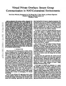
through the SNMP interface module. Management information related to the Resource Agents is stored in a database and is used by the processing module to dynamically create HTML pages which are then forwarded to the Web server. For example, the Web server may request the processing module to retrieve the information of the connections established by a MIBlet. After the information is retrieved and stored in the database, the processing module use this information to dynamically build an HTML page, which displays in a tabular form the input port, the input VPI/VCI, the output port, the output VPI/VCI, and the bandwidth allocation for each connection established by the MIBlet. Figure 6 shows an example of such HTML page which also gives the traffic information for each of these connections in terms of the Peak Cell Rate (PCR), the Sustainable Cell Rate (SCR), and the Maximum Burst Size (MBS).
5.2.3
SNMP Interface
The SNMP interface is invoked by the processing module to handle SNMP messages. It is the interface between the processing module and the Resource Agents. The messages used by this interface are standard SNMP messages. The information received from the Resource Agents is stored in the database and/or sent directly to the processing module. To trigger the execution of a script or a signaling/routing controller, the SNMP interface sends a set-request to the Programmable Controller in the Resource Agent. To request for MIBlet creation, re-configuration or termination, the SNMP interface sends a set-request to the Request Controller in the Resource Agent. The format for these set-requests is described in the subsequent sections.
5.2.4
TCP Module
The TCP module carries out two main tasks. The first task is to transfer management scripts or controller software to the appropriate Resource Agents using TCP. Another task is to record the information related to registered Resource Agents. Once a Resource Agent becomes active, it
26
informs the Management Server and forwards some relevant information such as its IP address and communication port number.
Figure 6: Example generated HTML page containing the traffic table for a MIBlet
5.3
Resource Agent
There are four functional building blocks identified in the Resource Agent: (1) Request Controller, (2) MIBlet Controller, (3) Resource Controller, and (4) Programmable Controller. The first 3 building blocks focus on how a MIBlet provides CNRMS with a limited view of the switch’s resources; while the Programmable Controller is responsible for the customization and programmability of the VPN. In the Resource Agent, MIBlet Controller and Programmable Controller are instantiated for each VPN. Figure 7 shows the design of the Resource Agent. Detailed description of the building blocks will be presented in the following section. The specifications below are not intended to be exhaustive, but rather to capture the major features of the building blocks involved.
Programmable Controller
Signaling/ Routing Controller
Request Controller
Resource Agent
Others
MIBlet Controller Resource Controller
Figure 7: Architecture of Resource Agent.
27
5.3.1
Programmable Controller
The Programmable Controller is responsible for receiving a variety of functional software packages downloaded from the CNRMS, and these software packages are executed in the Programmable Controller. The Programmable Controller is a key building block that allows customers to have full customization of network control, and provides the Resource Agent with the intelligence for autonomous operation. Each CNRMS has its own Programmable Controller in the Resource Agent. Different kinds of software packages with different functionality can be downloaded to the Programmable Controller. Example is the signaling and routing control software required for each Virtual Network Switch, which is a logical subset of a switch. Section 6 will show how this control software allows ATM virtual network to support IP services. Other possible software packages can be used for congestion control [22], video stream management [23], and FCAPS.
The Programmable Controller contains four modules: (1) SNMP server, (2) Scripts MIB, (3) Load module, and (4) Execution module. The modules involved in the Programmable Controller are illustrated in Figure 8.
SNMP Server The SNMP server receives SNMP requests from the Management Server. SNMP get-request leads to the retrieval of one or more values from the MIB/MIBlet variable identified by the OID. SNMP set-request here is used to (1) update the value of the indicated variable, (2) download script (management or control software) from a remote location, (3) trigger the execution of a script, and (4) open a TCP connection to receive a script from the Management Server.
28
Scripts MIB The Scripts MIB contains references to executable objects which allow when invoked to receive, download or execute scripts. These object references are defined as follows:
ExecuteClass: responsible for loading and executing a script.
ReceiveClass: responsible for opening a TCP connection and receive scripts from TCP module in the Management Server.
DownloadClass: responsible for downloading scripts from remote locations.
Each of these object references has an OID in the MIB which is known by the Management Server. When receiving a set-request corresponding to one of these OIDs, the corresponding object reference is activated and the appropriate operation is executed.
SNMP
TCP
HTTP Load module
SNMP server
Execution module
Scripts MIB
Programmable Controller
Figure 8: Modules involved in Programmable Controller
Execution Module When the SNMP server receives a set-request pointing to the OID corresponding to the “ExecuteClass” object reference, it invokes the execution module. The name of the script to be executed is specified in the SNMP set-request as a parameter. The execution module first checks if the script exists in the Programmable Controller. If it does not exist, the Programmable Controller sends a response to notify the Management Server that the script is not available. Otherwise, the execution module loads and executes the script.
29
Load Module The Load module is responsible for transferring scripts using one of the two schemes: direct transfer mode, or indirect transfer mode. •
Direct Transfer Mode: When the Management Server wants to transfer a script to the
Programmable Controller, it forwards an SNMP set-request to the target Programmable Controller. The set-request encapsulates the OID corresponding to the “ReceiveClass” object reference. This object in turn invokes the load module for the script transfer. The load module then opens a TCP connection and sends a READY message to the Management Server to initiate the transfer. When the script is correctly received, the load module closes the TCP connection. • Indirect Transfer Mode: After receiving the set-request encapsulating the OID corresponding to the “DownloadClass” object reference, the Programmable Controller invokes the load module for indirect transfer. The load module then downloads the script from the remote site using the URL address specified in the set-request.
5.3.2
Request Controller
The Request Controller is invoked whenever a MIBlet creation request generated by a CNRMS is received. Upon receiving a MIBlet creation request, the Request Controller examines the request against predefined policies. An example policy is to limit the maximum amount of bandwidth that can be reserved by any CNRMS. If the request does not comply with the policies, the Request Controller sends a response to the CNRMS indicating that the request is rejected. Otherwise, the Request Controller checks to see if there are enough resources to create the requested MIBlet. If there are not enough resources, the controller sends a reject message to the CNRMS. If there are enough resources, (a) a service address, which is to be used by the CNRMS to communicate with its MIBlet Controller, is assigned to the newly created MIBlet Controller; (b) a MIBlet creation response, encapsulating the service address of the MIBlet Controller, is sent to the CNRMS
30
indicating that the request is accepted; (c) reservation parameters are fed into the newly created MIBlet Controller.
The Request Controller contains three modules. (1) SNMP server, (2) Scripts MIB, and (3) Registration module. The SNMP server is responsible for receiving MIBlet creation, reconfiguration, and termination request from the Management Server. These requests are forwarded in the form of SNMP set-requests. The object references in the Scripts MIB are defined as follows:
MIBletCreateClass: responsible for initiating a new MIBlet Controller
MIBletReconfClass: responsible for re-configuring a MIBlet Controller
MIBletTerminateClass: responsible for terminating a MIBlet Controller.
To create a MIBlet Controller, the Management Server sends a request pointing to the OID corresponding to the “MIBletCreateClass” object reference. The reservation parameters of the MIBlet are specified in the request. Upon receiving a MIBlet creation request, the “MIBletCreateClass” object initiates the registration module, which then examines if there are enough resources to create the requested MIBlet. If there are enough resources, a response encapsulating the IP address and the communication port number of the newly created MIBlet is sent to the Management Server to indicate that the request is accepted. Also, the reservation parameters are recorded in a database.
To re-configure a MIBlet Controller, the Management Server sends a request pointing to the OID corresponding to the “MIBletReconfClass” object reference. The registration module is then invoked to examine if there are enough resources for the re-configuration. If there are enough
31
resources, the reservation parameters of the MIBlet in the database are replaced with the reconfiguration parameters, and a response is sent to the Management Server to indicate that the request is accepted. To terminate a MIBlet Controller, the Management Server sends a request, which points to the OID corresponding to the “MIBletTerminateClass” object reference. This object then initiates the registration module to clear the reservation parameters of the MIBlet in the database.
5.3.3
MIBlet Controller
Once the MIBlet creation request is accepted by the Request Controller, the CNRMS can send requests, such as VC segment establishment and inquiry for switch information, to its MIBlet Controller. The latter maintains information about ports and VCI/VPI ranges reserved by its CNRMS. It also maintains the amount of hard and soft bandwidth reserved on each port. For requests not related to bandwidth, the controller checks to see if the requests comply with the reservation condition. For bandwidth related requests, the controller checks if the reserved hard bandwidth is already allocated or not.
If hard bandwidth is available, the request is then sent to the switch. If all the hard bandwidth is allocated while soft bandwidth is still available, the MIBlet Controller will send the request to the Resource Controller in order to compete for the shared bandwidth. If both hard and soft bandwidth are allocated, the request is rejected and a response is sent to the CNRMS notifying that the request is not successful.
The MIBlet definition provided by the MIBlet Controller is very similar to the switch’s MIB definition provided by the switch vendor. The MIBlet definition keeps all the important MIB groups in the switch’s MIB definition and omits the MIB groups that are not relevant to the CNRMS. Moreover, extra MIB groups can be added to the MIBlet definition. An example of an
32
extra MIB group, which contains the information about the reserved resources, is shown in Figure 9 in ASN.1. Each row in the portResTable contains the max VPI, the min VPI, the max VCI, the min VCI, the hard bandwidth and the soft bandwidth on a reserved port. The index used to pick a specific row out of the portResTable is the port number. The managed objects in this group are not physically implemented in the actual MIB in the switch. When the Management Server sends a get-request to get values from this MIB group, the MIBlet Controller will immediately provide the Management Server with the get-response and does not need to pass the get-request to the actual MIB in the switch.
5.3.4
Resource Controller
The main responsibility of the Resource Controller is to act as an arbiter when MIBlet Controllers compete with each other for shared resources. When the MIBlet Controllers need to compete for shared resources on behalf of their CNRMSs, the MIBlet Controllers will send the requests to the Resource Controller. Section 4.2.3, which presents the functions of the MIBlet Controller, will describe clearly when the MIBlet Controller will send the request to the Resource Controller.
The Resource Controller maintains the shared bandwidth for each port. Every time the controller receives a request for connection establishment, it computes the aggregate bandwidth usage for supporting this new connection. When the aggregate bandwidth usage reaches the amount of shared bandwidth, this implies that all the shared bandwidth is allocated and further requests will be rejected. If the request is accepted, (a) the request is sent to the switch; (b) the aggregate bandwidth is computed for accepting this new connection. If the request is rejected, the Resource Controller will notify the CNRMS.
33
portResTable OBJECT-TYPE SYNAX SEQUENCE OF PortResEntry ACCESS not-accessible STATUS mandatory DESCRIPTION “ A table of information about reservation for each port.” :: = { allocationGroup 1 } portResEntry OBJECT-TYPE SYNTAX PortResEntry ACCESS not-accessible STATUS mandatory DESCRIPTION “ A table entry containing reservation information for each port.” INDEX { ResPort } ::= { PortResTable 1} PortResEntry :: = SEQUENCE { ResPort INTEGER, hardBW INTEGER, softBW INTEGER, minVPI INTEGER, maxVPI INTEGER, minVCI INTEGER, maxVCI INTEGER, } -- minVPI and maxVPI defines the reserved VPI range -- minVCI and maxVCI defines the reserved VCI range
Figure 9: Definition for portResTable
5.4
Communication Interfaces
In order to provide, customize and manage a virtual network, the CNRMS, the VPN provider management system (referred to as the Provider VNRMS in the following) and the Resource Agents need to communicate with each other (see Figure 10). Three categories of interfaces are specified: (a) communication between Provider VNRMS and Resource Agents, (b) communication between CNRMS and Provider VNRMS, and (c) communication between CNRMS and Resource Agents. Network Management Layer
Provider VNRMS
(b)
(a)
CNRMS (c)
Resource Management Layer
Resource Agent Resource Agent
Root-VN MIBlet Controllers
Child VN
Spawning
Figure 10: Interfaces for Provision and Customization.
34
5.4.1
Communication between Provider VNRMS and Resource Agents
There are six messages involved in the communication between Provider VNRMS and Resource Agents: MIBlet creation request/response, MIBlet re-configuration request/response, and MIBlet termination request/response. The requests are sent from the provider VNRMS to the Request Controller in the Resource Agent. For each of the requests, a corresponding response is returned from the Resource Agent to the VNRMS. MIBlet Creation: To spawn a VPN, a MIBlet is created at the level of each ATM switch involved in the VPN. In particular, VPI/VCI space and bandwidth are partitioned and allocated to the MIBlet. After each switch’s MIBlet is created, a VPN can be simply represented as a collection of the newly created MIBlets. The reservation information of the MIBlet creation request includes: (1) a port number that the VNRMS wants to reserve; (2) the VPI range that the VNRMS wants to reserve on the port specified; (3) the VCI range that the VNRMS wants to reserve on the VPIs of the specified port; (4) the amount of hard bandwidth, and (5) the amount of soft bandwidth required on the specified port. These configuration information are obtained by the management server from the CNRMS Web-based management interface as shown in figure 11. The MIBlet creation response specifies whether the request is accepted or not. If the request is accepted, a Service Address, which is used by the VNRMS to communicate with its MIBlet Controller, is included in the response.
35
Figure 11: Interfaces for Provision and Customization.
MIBlet Re-configuration: A CNRMS may require a different amount of bandwidth and possibly a different network topology at different times, based on the timely profile of its network traffic. The MIBlet reconfiguration request allows the VNRMS to change the configuration during the lifetime of the MIBlet on behalf of the corresponding CNRMS. The parameters that need to be specified in the MIBlet re-configuration request are the same as those specified in the MIBlet creation request. In addition, the Service Address of the MIBlet Controller is specified in the request. The MIBlet Reconfiguration response indicates whether the request is accepted or not. MIBlet Termination: The MIBlet termination request specifies the Service Address of the MIBlet that the customer and/or the provider want to terminate. The MIBlet termination response is used as an acknowledgment of the MIBlet termination.
36
5.4.2
Communication between CNRMS and Provider VNRMS
The messages in the communication between CNRMS and provider VNRMS are also related to creation, re-configuration and termination. However, these messages refer to the creation, reconfiguration and termination of the whole VPN, rather than each MIBlet in the VPN. VPN Creation: The VPN creation request specifies the location of the customer’s systems that plan to connect to the requested VPN. Here, customer’s systems refer to customer’s switches or routers. Another information included in the request is the bandwidth requirements for the connections among the customer’s systems. The VPN creation response specifies whether the request is accepted or not. If the request is accepted, the Service Addresses of all the MIBlet Controllers involved in the VPN are included in the VPN creation response. VPN Re-configuration: When CNRMS determines that re-configuration of VPN is required, it will send a VPN Reconfiguration request to the provider VNRMS. The information included in the VPN reconfiguration request and response is the same as that included in the VPN creation request and response, respectively. VPN Termination: When CNRMS wants to terminate its VPN, it sends a VPN termination request to the provider VNRMS. The provider VNRMS will then send the MIBlet termination requests to all the Resource Agents involved in the VPN to terminate the MIBlets. The VPN termination response is used as an acknowledgment of the VPN termination.
Also, part of the communication between CNRMS and Provider VNRMS but currently not part of our system design are all issues mentioned in Section 3.1.1 (e.g. billing and complaints).
37
5.4.3
Communication between CNRMS and Resource Agents
To operate and manage the VPN, the CNRMS interacts with the MIBlet Controllers in the Resource Agents. To manage MIBlet and monitor traffic, a management protocol, such as SNMP or CMIP, is used. Since the testbed in our laboratory uses SNMP, the protocol used for communication between CNRMS and MIBlet Controller is SNMP. Thus, the messages used by a CNRMS to interact with MIBlet Controllers are standard SNMP get-request and set-request messages. Moreover, to customize virtual network and to allow autonomous operations of the Resource Agents, CNRMS is responsible for downloading appropriate software packages to the associated Programmable Controllers in the Resource Agents.
The CNRMS accesses the MIBlet as if it is directly accessing the MIB in the switch. However, the CNRMS can only access the values related to the reserved resources. The MIBlet Controller will provide the CNRMS with a MIB definition (called MIBlet definition), which defines the structure of the MIB objects. The MIBlet definition provided by the MIBlet Controller to the CNRMS is very similar to the switch’s MIB definition provided by the switch vendor. The MIBlet definition must keep all the important MIB group in the switch’s MIB definition such as: the Port Group which contains the managed objects concerning the ports, the Path Group which specifies the managed objects concerning the virtual paths, and the Channel Group which contains the managed objects concerning the virtual channels. Other MIB groups that are not relevant to the CNRMS such as Temp Group, which contains the temperature sensor information of the switch, are omitted in the MIBlet definition. Moreover, extra MIB groups can be added to the MIBlet definition. Section 6.3, which presents our prototype implementation, gives an example of an extra MIB group.
38
6
CNRMS Application to the Provision and Customization of VPNs
For the provision of a VPN, the CNRMS first sends a VPN creation request to the VPN provider management system. The latter, after receiving the request, determines an appropriate VPN topology and determines the resource reservation at each Resource Agent involved in the VPN. It then sends the MIBlet creation requests to the Resource Agents. If the Resource Agent involved in the VPN has enough resources for the creation request, it will then reserve the requested resources for the newly created MIBlet Controller. When the VPN is set up successfully, a VPN creation response is sent to the CNRMS indicating that the VPN is created. The response also provides the CNRMS with the addresses used to communicate with the MIBlets involved in the VPN, and informs the CNRMS about the MIBlets’ resource reservations.
For the customization of VPN, the CNRMS first downloads the appropriate software packages to the corresponding Programmable Controllers, after receiving a VPN creation response indicating that the VPN is set up successfully. By executing these downloaded software packages in the Programmable Controllers, the VPN can support OAM functions and algorithms of customer’s choice. Also, the CNRMS communicates with the MIBlet Controller to manage the VPN and to monitor the traffic characteristics of the VPN. Based on the timely profiles of the traffics, the CNRMS may request for re-configuration of VPN to accommodate the rapidly changing VPN customer needs. Fault occurrence may also lead to the re-configuration of the VPN.
In the remaining of this section, we will show how signaling and routing software is downloaded to allow customization of ATM virtual network for supporting IP services. We will particularly discuss how the developed system can support different existing techniques for integration of ATM and IP, such as IP switching [24] and Classical IP over ATM [25].
39
Existing technologies for integration of ATM and IP can be categorized into two major approaches: (1) IP over ATM, and (2) IP switching. For IP over ATM, several techniques, such as Classical IP over ATM [25] and LAN Emulation (LANE) [26], have been developed. These techniques propose to “layer” IP over ATM without changing the ATM network. These approaches hide the physical network from the IP layer by treating the ATM layer as an opaque network cloud. For IP switching category, ATM switches are augmented to participate in IP routing. One example that falls into this category is the “Integrated Services Internet with RSVP over ATM short-Cuts” (ISAC) [27], developed at the University of Toronto. An ISAC router consists of a core ATM switch connected to a router controller. The controller is responsible for routing and RSVP signaling, whereas the underlying ATM switch is solely responsible for switching data packets. Other examples that fall into this category are Ipsilon’s IP switching [24] and Cisco’s Tag switching [28].
6.1
IP Switching based VPN
In our testbed, in order to configure an IP switching based VPN, the ISAC controller is downloaded to all the Programmable Controllers involved in the virtual network. The ISAC controller together with the MIBlet Controller are considered as a Virtual Network Switch (VNS), which is a logical subset of the ATM switch, configured to support integrated services IP. ISAC controller accesses the MIBlet Controller as if it is directly accessing the actual switch. The MIBlet Controller is responsible for access control and allows ISAC controller to use only the reserved resources.
ISAC controller need to inquire its corresponding MIBlet Controller about the reserved VPI/VCI ranges. This information helps the ISAC controller to conform to the reservation condition. Then, ISAC controller starts operating and setting up connections using only the VPI/VCI within the reserved ranges. Also, the ISAC controller only exchanges routing information with other
40
ISAC controllers involved in the VPN. This means that each controller only acquires the information of the network subset (virtual network), not the whole network.
To/From CNRMS
To/From CNRMS
SNMP, CMIP
SNMP, CMIP
Programmable Controller
Programmable Controller
ISAC Controller GSMP
Ipsilon’s IP switching Controller GSMP
MIBlet Controller
MIBlet Controller
Resource Agent VNS
GSMP, SNMP, CMIP, …
Switch agent
VNS
ATM Switch
Figure 12: An Example of Partitioning a Switch’s Resource Agent into Two VNSs.
Figure 12 shows an example of a switch’s Resource Agent with two signaling/routing controllers: ISAC Controller and Ipsilon’s IP switching Controller. This switch is considered as two Virtual Network Switches (VNSs), belonging to two different VPNs. Ultimately, it is desirable that MIBlet Controllers can provide different kinds of communication interfaces. For example, the interface between MIBlet Controller and signaling/routing controller may use protocols such as GSMP [29] or qGSMP [30], while the management interface between MIBlet Controller and CNRMS may use protocols such as SNMP or CMIP.
6.2
IP over ATM based VPN
To configure an IP over ATM based VPN, e.g. Classical IP over ATM or LANE, an ATM signaling/routing controller is required for each Programmable Controller in the VPN. As a result, the VPN can operate as a conventional ATM network, and the routing can be done using ATM Forum’s private network-to-network interface (PNNI). For IP “layered over” ATM, the components used in IP over ATM technique are downloaded to the appropriate Programmable Controllers in the VPN.
41
ATM signaling/routing controller requests its MIBlet about not only the VPI/VCI ranges, but also the bandwidth information, because the PNNI protocol used by the controller requires the exchanges of QoS information. Also, ATM signaling/routing controller only exchanges routing information with other controllers involved in the VPN. Furthermore, the ATM signaling/routing controllers of different VPNs use different VPI/VCI spaces to carry out signaling and routing. This allows separation amongst signaling/routing packets of different VPNs.
Network Management Layer
CNRMS VNS
Resource Management Layer
ATM s/r controller
ATM s/r controller
ATMARP server
MIBlet Controller
Programmable Controller
MIBlet Controller
Resource Agent
VNS Legend
VNS
VNS
Programmable Controller
ATMARP server
VNS
VNS
Resource Agent Virtual Network considered as a Logical IP Subnet (LIS)
s/r: signaling/routing
Figure 13: Virtual Network for Classical IP over ATM.
Figure 13 illustrates an example of operating a VPN as a Logical IP Subnet (LIS) using Classical IP over ATM model. In this configuration, the role of the CNRMS is to download not only the ATM signaling/routing controllers, but also the server component for Classical IP over ATM (i.e. ATMARP server). After a VPN is set up by the provider VNRMS, the CNRMS first downloads the ATM signaling/routing controllers to the Programmable Controllers of all the VNSs involved in the VPN. Then, the CNRMS selects one of the VNSs in the virtual network to act as the ATMARP server. After a proper location is selected, the ATMARP server software is downloaded to the Programmable Controller of the selected VNS. To resolve the addresses of nodes within the LIS, all ATMARP clients within the LIS are configured with the ATM address of the ATMARP server. The client first establishes a connection to the ATMARP server, using the configured address. Once the connection to the ARP server has been established, the ARP server sends an Inverse ARP request on the new connection to obtain the client’s IP address.
42
Therefore, over time, the ARP server knows the mappings between IP and ATM addresses of all the nodes in its LIS. The client may then use the server to request the address mapping of any node in the LIS.
In fact, the customer may choose not to implement the server component on the ATM switch, which is in the domain of the VPN service provider. Instead, the customer may implement the server component in its own device attached to the ATM virtual network. In this case, the OAM system is only responsible for providing a conventional ATM virtual network and the VPN users will configure the IP over ATM VPN on their own.
6.3
Customer Monitoring of a VPN
VPN monitoring is one of the management examples we use to demonstrate the CNRMS capability to support full customization of network management. Monitoring is important because it provides all other management functions with the information necessary to make management decision and perform the appropriate actions. In this section, we describe the monitoring and computation of call blocking probability. The call blocking probability of each MIBlet is one of the important information for the CNRMS to evaluate the performance of its virtual network. To obtain this information, the CNRMS downloads monitoring software to all the Resource Agents involved in the VPN. The monitoring software polls the MIBlet for two values: 1) the number of connection requests received, and 2) the number of connection requests rejected. The management software polls every T minutes (Polling interval) for these two counter values. The call blocking probability is computed as the connection requests rejected in Polling interval (T) divided by the connection requests received in the same polling interval T.
The monitoring software uses two input parameters:
43
•
Polling interval (T): indicates the interval of polling the MIBlet for the call blocking information.
• Threshold: if this threshold is exceeded, an alarm notification is generated and is sent to the CNRMS. Varying these two parameters allows the CNRMS to adjust how often and under what circumstances it will receive an alarm notification. By receiving these alarm notifications, the CNRMS obtains the call blocking probability information of the MIBlets involved in the VPN. Through the analysis of this information and some other performance-related information, the CNRMS may determine whether its subscribed VPN requires re-configuration or not. If the CNRMS decides that re-configuration of VPN is required, it sends a VPN re-configuration request to the provider VNRMS to request for more resources to be allocated to the VPN.
Downloading management software to the Resource Agents to monitor the information is more preferable than sending polling requests continually to the Resource Agents. In general, having the management software closer to the managed resources allows us to reduce the management traffic in the network, as well as to speed up the reaction to network events.
6.4
Experimental Testbed
In order to configure VPN for different control architectures, different signaling/routing controllers are required. Our testbed spawns three virtual networks from the physical ATM network. As illustrated in Figure 14, a first VPN serves as an Integrated Services IP (IS-IP) network, a second VPN serves as an ATM network, and a third one serves as a Best Effort IP (BE-IP) network. ISAC [27] is used as the signaling/routing controller for the IS-IP virtual network in our testbed. The ISAC controller is responsible for routing and RSVP signaling. It also performs parameter mapping which maps the QoS parameters from IS-IP model to appropriate ATM services. The signaling/routing controller used for the ATM VPN is the ATM
44
signaling/routing controller, which we developed according to the ATM signaling standard. The BE-IP VPN is required for the operation of ISAC controller because ISAC switch controllers employ RSVP as a signaling protocol and RSVP delivers control messages through BE-IP services. For the time being, BE-IP control mechanisms and services provided by our ATM switch are used for the control of the BE-IP VPN. In other words, we are exercising programmability and resource allocation flexibility for IS-IP VPN and ATM VPN only.
IS-IP Controller(s)
ATM Controller(s)
BE-IP Controller(s)
VN 1
VN 2
VN 3
Spawning ATM Network
Figure 14: Partitioning of the ATM Testbed
7
Conclusion and perspective research
This paper addressed customer management of VPN services and presented a Web-based Customer Network Management System (CNRMS) architecture and implementation. The integrated control and management of VPNs through the CNRMS is organized into a network management layer and a resource management layer. At the network management layer, networkwide operation and management functions are applied. For each VPN, specific operation and management functions can be applied, allowing for customized control and management of VPN resources, or VNRs. The resource management layer deals with the management of individual network resources. VNRs in a provider domain are represented by Resource Agents, which handle partitioning, and allocation of resources to customers. Resource Agents also host programmable controllers belonging to the various CNRM systems, enforcing customers’ policies for the control and management of the resources allocated to these customers.
45
This paper particularly emphasized the design architecture of the Resource Agent. It focused on the partitioning function of VPN resources through the provision of MIBlets. MIBlets are introduced as effective means to design VPNs as well as customizable management. They result from a logical partitioning of MIBs to provide CNRM systems with abstract and selective views of the network resources. Static and dynamic partitioning schemes are combined to support VPNs with differing QoS requirements, and to allow for flexible resource allocation (e.g., by enabling network-level multiplexing). In this paper we have addressed partitioning of SNMP MIBs to experiment the VPN structuring and the programmability of VNRM architecture using the resources of our ATM network testbed. However, the MIBlet concept is generally applicable for partitioning any type of network resources. Indeed, all network devices are already endowed with MIBs containing large numbers of managed objects, which can be selectively abstracted to design VPNs and to provide interoperable interfaces accessible by control and management software.
This paper also described the implementation of network control and management functions in the customer domain by downloading software into the Resource Agents encapsulating the network devices. This is achieved by a programmable controller, within the Resource Agent, capable of hosting and executing Java mobile code. As a result, the controller can be dynamically programmed to automate the analysis of monitoring data and the efficient execution of customized operations. Executing delegated control and management functions at the same level as MIBlets (i.e., close to the managed devices) improves the response time for customer management applications. Among the characteristics of the prototype implementation there is: -
The use of a Web-based management interface where Java applets are used to display dynamic information such as evolving network traffic graphics on a standard Web browser. The Web-based management interface also implements user authentication.
46
-
The use of Java Servlets loaded dynamically to perform specific management tasks in the server, such as building HTML pages encapsulating collected and filtered monitoring information and appropriate Java Applets.
-
The use of the standard Java Class Loader to dynamically load and execute management script objects at the level of the resource agent.
Using the Java language capability for network programming allows the portability of the implemented prototype to all environments supporting a Java Virtual Machine. Using a secure Web-based network management interface allows for a universal and seamless access from everywhere in the network. The management policies proper to a customer are downloaded from the customer’s server in the form of Java scripts and SNMP requests. They are enforced in the network to control the conformance of the behavior of the customer controller, and thereby the resources allocated to the customer, according to the customer’s goals.
The evolution of this research work and our perspective research is illustrated by figure 15. At this stage, the goal of the VNRM architecture is to provide a fully programmable networking environment. Dynamic configurability in network topology and resource capability is enabled by the introduction of extensible agents (Resource Agents), which perform delegated tasks of MIBlet management/control
in
an
autonomous
manner.
This
migration
from
an
ordinary
management/control architecture to an agent-based VPN management/control architecture is depicted in Figure 15 (a) and (b). Note that there is no architectural change required for example for the IS-IP controller (ISAC) in our network testbed. Rather, the Resource Agent transparently fulfills partitioning of resources, arbitration of resource usage, and access control.
47
IS-IP Cntr
IS-IP Cntr
BE-IP Cntr
ATM Cntr
IS-IP Cntr
BE-IP Cntr
ATM Cntr
IS-IP Cntr
BE-IP Cntr
ATM Cntr
MIBlet
MIBlet
MIBlet
MIBlet
MIBlet
MIBlet
MIBlet
MIBlet
MIBlet
Resource Agent (RA)
Resource Agent (RA)
MIB S witch Controller
MIB
MIB
(a) "Open" signaling
(b) "Open" signaling with MIBlets
MIB
(c) "Open" signaling with MIBlets & programmable agent
Cntr
(d) Programmable switch with MIBlets
Figure 15. Node Migration from "Open" to "Programmable".
Compared to the traditional "closed" approach for switch control, the "open" approach has a number of advantages to include independent development of control algorithms and mechanisms from switch hardware, and dynamic binding of control architectures to switches. However, the physical separation of the control software from the switching hardware introduces a few extra communication procedures, which may impact the performance of overall control systems. We have reduced them by employing programmability in the OAM VNRM architectures (Figure 15 (c) ). By defining appropriate service primitives and APIs in a node, local management/control functions can be easily implemented and deployed in the node. In order to fully automate code deployment within a node, a mobile code-hosting environment has been included in the node. In this way, new OAM functions and algorithms are injected into a node from outside, emulating the "open" control environment with less performance penalty. The future phase of our implementation is depicted by figure 15 (d) where the control and management functions of the VNRM system will be integrated within the active switch developed in the NAL lab with programmable hardware [31]. Our ultimate aim is to achieve a truly programmable management environment facilitating the creation and introduction of new network services, including VPN services, and a customizable operation and management of network resources.
48
8
References
[1] Paul Ferguson and Geoff Huston , White paper: "What is a VPN?", Revision 1, April 1998. [2] The ATM Forum, “Multi-Protocol Over ATM Specification v1.0,” af-mpoa-0087.000, July 1997. [3] S. Hanks, T. Li, D. Farinacci, P. Traina, RFC1701, “Generic Routing Encapsulation,” October 1994. [4] A. Valencia, K. Hamzeh, A. Rubens, T. Kolar, M. Littlewood, W. M. Townsley, J. Taarud, G. S. Pall, B. Palter, W. Verthein,, “Layer Two Tunneling Protocol ‘L2TP’,” draft-ietfpppext-l2tp-10.txt, March 1998. [5] K. Hamzeh, G. Singh Pall, W. Verthein, J. Taarud, W. A. Little, “Point-to-Point Tunneling Protocol – PPTP,” draft-ietf-pppext-pptp-02.txt, July 1997. [6] D. Waitzman, C. Partridge, S. Deering, RFC1075, “Distance Vector Multicast Routing Protocol,” November 1988. [7] R. Chandra, P. Traina, T, Li, RFC1997, “BGP Communities Attribute,” August 1996. [8] E. Chen, T. Bates, RFC1998, “An Application of the BGP Community Attribute in Multihome Routing,” August 1996. [9] Callon, P. Doolan, N. Feldman, A. Fredette, G. Swallow, A. Viswanathan, "A Framework for Multiprotocol Label Switching," draft-ietf-mpls-framework-02.txt, R. November 1997. [10] S. Kent, R. Atkinson, “Security Architecture for the Internet Protocol,” draft-ietf-ipsec-archsec-04.txt, March 1998. [11] Proceedings of OPENARCH '99, New York, N.Y. USA, March 26-27, 1999. [12] Proceedings of OPENSIG Workshop, Toronto, October 5-6, 1998. [13] D. Tennenhouse, J. Smith, W. Sincoskie, D. Wetherall, and G. Minden, "A Survey of Active Network Research", IEEE Communications Magazine, January 1997.
49
[14] Andrew Do-Sung Jun and Alberto Leon-Garcia, "Virtual Network Resources Management: A Divide-and-Conquer Approach for the Control of Future Networks", IEEE Global Telecommunications Conference (GlobeCom'98), Sydney, Australia, November 1998. [15] Walfrey Ng, Andrew Do-Sung Jun, HungKei Keith Chow, Raouf Boutaba and Alberto Leon-Garcia, “MIBlets: A Practical Approach to Virtual Network Management”, in Proc. of IFIP/IEEE IM’ 99, Boston, May 1999. [16] J.P. Martin-Flatin, S. Znaty, and J.P. Hubaux. "A Survey of Distributed Enterprise Network and Systems Management Paradigms". Journal of Network and Systems Management, 7(1):9-26, March 1999. [17] K. El Guemhioui and Raouf Boutaba, “Webification of Network Management”, in Proc. of Notere’97 Colloq. (in French), Pau, France, Nov. 1997. [18] J. Won-Ki Hong, J. Kong, T-H Yun, J-S. Kim, J-T Park, and J-W. Baek, “Web-based Intranet Services and Network Management”, IEEE Communications Magazine, Vol. 35 No. 10, October 1997. [19] N. Anerousis, “ Scalable Management Services using Java and the World Wide Web”, in Proc. of DSOM’98, Newark, USA, October 1998, pp.79-90. [20] J.P. Martin-Flatin, L. Bovet, and J.P. Hubaux. "JAMAP: a Web-Based Management Platform for IP Networks". In Proc. of DSOM'99, Zurich, Switzerland, Oct. 1999, pp. 1700:164-178. [21] A. Ghalamallah and R. Boutaba, “Implementing a Distributed Web-based Management System in Java”, IEEE ITS/SBT’98, San Paulo, Brazil, 7-10 August 1998. [20] A. Mehaoua, Y. Iraqi and A. Ghlamallah, “A Self-Regulating Congestion Control Scheme Using an Intelligent Multi-Agent Architecture”, Proc. IFIP/IEEE MMNS'97, Montreal, Canada, July 1997. [23] Amir, E., McCanne, S., and Zhang, H. “An application-level video gateway”, Proceedings of ACM Multimedia ’95, November 1995.
50
[24] P. Newman, T. Lyon, G. Minshall, “Flow Labelled IP: A Connectionless Approach to ATM,” Proceedings of IEEE Infocom, March 1996. [25] Laubach, M., “Classical IP and ARP over ATM”, IETF, RFC 2225, April 1998. [26] B. Ellington, “LAN Emulation over ATM, Version 1.0,” ATM Forum, af-lane-0021.000, January 1995. [27] HungKei Keith Chow and Alberto Leon-Garcia, "Implementation and Performance Evaluation of ISAC: Integrated Service Internet with RSVP over ATM shortCuts," ICC'98, June 1998. [28] Y. Rekhter, B. Davie, D. Katz, E. Rosen, and G. Swallow, “Cisco System’s Tag Switching Architecture Overview,” IETF, RFC 2105, February 1997. [29] "GSMP: General Switch Management Protocol", Ipsilon Networks, IETF RFC 1987. [30] C. M. Adam, A. A. Lazar and M. Nandikesan, "QOS Extensions to GSMP", Technical Report 471-97-05, Center for Telecommunications Research, Columbia University, New York, April 1997. [31] M.R. Hashemi and A. Leon-Garcia, "A RAM-Based Generic Packet Switch with Scheduling Capability", IEEE BSS’97, Taipei, December 1997.
51