WIDE Workflow Development Methodology∗ L. Baresi, F. Casati, S. Castano+ , M.G. Fugini, I. Mirbel, B. Pernici Dipartimento di Elettronica e Informazione - Politecnico di Milano Piazza L. da Vinci, 32 I-20133 Milano (Italy) baresi,casati,castano,fugini,mirbel,
[email protected] ABSTRACT
The development of workflows (WFs) for complex organizations to be interfaced with existing information systems requires a specific methodological approach to guarantee benefits and effectiveness of the final results. In fact, the WF should be well integrated in the organization both from the technical and the organizational point of view. While the characteristics of the Workflow Management System (WFMS) platform adopted in the implementation are relevant to establish the boundary between the workflow system and other related applications, it is also important that the analysis and design phases are developed independently of those characteristics. The WF development methodology proposed in this paper starts with an analysis phase based on UML, adopted for business process descriptions and business goals. The design phase proposes a pattern-based approach to workflow schemas design, based on the WIDE WF model. This model allows a flexible representation of the exceptions which may occur during WF execution. It also considers the interaction of the WF with external applications and information systems. Finally, the paper briefly discusses the mapping to commercial and prototype WFMSs. Keywords
Workflow design, patterns, exceptions, triggers. 1. INTRODUCTION
WF design is a complex activity in particular when considered in the context of a broader business process analysis in the organization linked to information systems development. Research on WF design has focused in recent years mainly on modeling issues, while little effort has been devoted to developing methodological approaches to WF design. The Workflow Coalition [16] focuses on architectural issues, providing a glossary for modeling concepts; methodological approaches to design are still outside their scope. The problem of paying attention to the WF development process is emerging as a concern for some vendors of commercial systems. A first document pointing out the importance of a methodological approach to WF design is [6]. Other examples are reported in the manuals for WF design accompanying some commercial products (see, for instance [9]).
In these manuals some guidelines for the introduction of a WF in the organization are discussed, in particular with reference to the design of the WF schema and to the association of executing agents. No general approaches have been provided to the analysis and design phase, the focus being on the specific characteristics of a given system. On the other hand, the Unified Modeling Language (UML) [1,13] is now broadly adopted for software development, including notations for process modeling that can be useful for WF development. The effort is devoted more to providing a set of notations for modeling purposes than to guiding the designer through the different design steps. Some efforts to extend and tailor UML to process and WF modeling are appearing in recent literature [4,14,15] proposing extensions to UML activity diagrams, in order to capture aspects typical of office activities, such as exceptions and activities performed by agents in parallel. Also in this case, the issue of guiding the development process is rarely treated. The need for interfacing WFs with existing information systems and with external applications is relevant when the WFMS provides an engine for flow automation, without providing any support for managing user interfaces and forms. In such cases, the design of the WF application and the design of external applications proceeds in parallel, and it is important to synchronize such activities. In the area of requirements engineering, the emphasis is on capturing application goals, in addition to the functional and data-related requirements of applications. Different approaches to goal driven requirements engineering classify goals according to desired systems states and according to policy, functional, and domain levels (as in [12]). Other approaches propose goal identification based on scenarios and on the organizational structure (bottom-up and top-down) [2], and introduce goal specification languages (e.g., [13]). Reusability of specifications and designs through patterns and frameworks is another approach gaining attention in software development [3,14]. The approach is also suitable for WF development, with the proper adaptations. In general, WF development should be tackled from a broader perspective, identifying the requirements of the WF applications, linking the design choices to general goals that can guide the development of the WF structure, and applying reuse techniques. In this paper, we propose a WF development methodology covering the whole process, from the initial analysis phase to the implementation on specific WFMSs. The novelty of the approach is in the emphasis on exceptional vs. normal flow analysis, and on the design of the WF in close rela-
tionship with the design of the interaction with existing information systems and external applications. In the analysis phase, described in Section 2, we start from UML descriptions of business processes, and, through the analysis of their goals and their characteristics we determine the "workflowability" of proposed business processes. The design phase, where the designer specifies the detailed WF structure and its interfaces towards existing applications, is described in Section 3. The WF schemas are designed adopting the WIDE models (process model and organizational model) developed within the WIDE (Workflow on an Intelligent and Distributed database Environment) ESPRIT Project [7]. In the design, the emphasis is on the normal process flow, on the decomposition into sub-processes and tasks, and on the definition of exceptions. A pattern-based approach is adopted for specifying typical exceptions to the normal flows. Finally, in Section 4, the paper discusses how the output of the WF design can be mapped into commercial WFMS products and standards.
design and implementation, and is also efficient in documenting the analysis phase; 3) UML is an emerging standard language for object-oriented development [8]. Business Process
Goals
External IS
Analysis
Identified WFs, roles, goal matrix
WF Design
2. OVERALL METHODOLOGY AND ANALYSIS PHASE
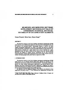
Fig.1 shows the steps of the methodology. It shows the relationship between WF design activities and the business context. WF design starts from the results of the analysis phase where business goals, business processes and external information systems are specified. A subsequent implementation phase maps the WF design into an executable WFMS using specific WF tools. The methodology does not deal directly with BPR. We assume the existence of welldefined processes, and consider that changes to these processes are needed only as a result of the introduction of the WFMS to support process execution. For example, the process could require some modifications due to the introduction of automated support, or the process could be decomposed in different ways according to assignment of activities to agents, distribution requirements, and so on. The analysis phase aims at defining the WF(s) that implement a given business process, the system boundary for each identified WF, and interactions with other WFs and with external information systems. WF analysis starts from a description of the business process to be implemented. A list of business goals is provided to guide WF development, by taking into account the context of the business process. The aim is to provide a list of candidate WFs to implement the business process and to show the correspondences between business goals and candidate WFs. Several modeling techniques have been proposed and adopted in the literature for describing the structure and the business processes of an enterprise, mainly for analysis and re-engineering purposes [9,11,12]. We adopt UML [13] as the supporting notation for describing business processes in an object-oriented way. The main reasons for adopting a UML description for the analysis phase are: 1) Object orientation has been recognized as a valuable mean to model reality, thus to model business processes [4]; 2) UML supplies a homogeneous framework where analysts and designers can move from requirements definition (business process description) to
Exceptions
WF Schema
Interactions with external applications
Mapping to Target WF Systems
Specifications in the WF models provided by the target systems
Figure 1: WIDE WF Development Methodology UML elements and notations have to be tailored to represent the typical business process concepts. We give some requirements on the use of UML for describing business processes in WF design. Moreover, since the business context lacks in all UML models [1], we require that a list of business goals be provided along with the UML description of the business process. All these requirements aim at ensuring that enough information is available to the subsequent development phases, and at minimizing the need of iterations between business process definition and the analysis phase. At the same time, the provided description should not impose a heavy burden on the user before the analysis. In the paper, we illustrate the WIDE methodology through an example dealing with the “travel arrangement” process of the (fictitious) travel firm Global Travel International (GTI) [7]. The GTI organization consists of a number of sale offices (front offices) where customers are advised on travel aspects, like transportation and accommodation, trips are booked, and administrative processes are initiated. The firm has two central departments (back offices): the travel department and the financial department. Front and back offices are interconnected by a computer network. When a
customer wants to book a trip, a sale person at the front office configures a travel package by selecting the appropriate transportation and accommodation with the client. Packages are uniquely identified by a number. Based on the cost calculation, the packages can be accepted, modified or discarded by the customer. If the package is accepted, the trip is booked and the travel and financial departments are notified. Booking requires the customer's data. Such data are required not earlier than this point, as a trip may also be canceled, based on the costs calculation. In case of cancellation, the data-entry activity would result in wasted time. The travel department acknowledges the trip booking with all relevant travel details. For this purpose, an acknowledgment letter is produced and sent to the customer. The financial department issues an invoice which, after a check, is sent to the customer. 10 days after invoice issuing the payment is checked. If the payment has not been received within 10 days, a reminder is sent to the customer. The checking process can be repeated for a limited number of times: after 30 days (3 checks), the booking is canceled. When the invoice payment has been acknowledged by the financial department, the travel documents (e.g., plane tickets and hotel vouchers) are prepared and forwarded to the customer. In the analysis phase, we assume that a description of the business process is available covering the following perspectives: 1) functional perspective, concerning the process activities and the involved information objects; 2) organizational perspective, concerning agents and roles involved in process execution; 3) business perspective, concerning business goals capturing the business rules and objectives of the process. In the following, the UML models to be provided for each perspective and their use in the analysis are described. 2.1 Input to the analysis phase 2.1.1 Functional perspective
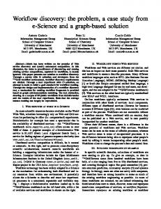
The functional perspective focuses on the operational structure of the business process. The core description of the business process deals with its generic representation through use case diagrams, and with examples of use of the business process (scenarios) through sequence diagrams. Use case and sequence diagrams are usually employed as basic notations for business process requirements [4]. They seem to provide a high comprehensibility for non-IT users [1], which is a relevant aspect during the analysis. The use case diagram representing the whole business process identifies: i) the system boundary, graphically shown by a rectangle, and ii) the actors involved in the business process, both internal and external, and their interactions with the system. Internal actors represent organizational roles or software applications that perform process activities. External actors are entities interacting with the process. These two kinds of actors are graphically represented with different icons. The use case diagram comprises also the representation of the main sub-processes of the business process and their relationships with actors, to express a use, an activation or a communication between the actor and the
use case. Each main sub-process in the use case diagram can be further detailed through another use case diagram. In Fig. 2, we show the use case diagram for the GTI process. A set of scenarios is associated with each sub-process to simulate the use case diagram. Scenarios allow the representation of control flow aspects, not derivable from the use case diagram. Scenarios are represented by means of sequence diagrams, which describe how the involved entities (actors, internal components) co-operate.
Select & book trip Customer Travel agent
P ayment management
Travel secretary
Travel Documentation
External accounting information system
Figure 2: Use-case Diagram for the GTI business process Scenarios are required to describe both the “normal” behavior and the “exceptional” behavior of a given subprocess. If several exceptional behaviors are identified in the same sub-process, different scenarios must be provided each describing an exceptional behavior of the sub-process itself. Exceptional scenarios should be defined to show how the system behaves in correspondence of decision points: possible alternative behavior(s), not considered in the “normal” scenario, must be supplied to explain how the process manages these exceptions. Sequence diagrams are preferred to collaboration diagrams since they emphasize the interaction along the time sequence, which is very relevant for WF design. The Select and book trip sub-process of the GTI example is further described through the sequence diagrams in Fig.3. We show a scenario for the normal behavior of the business process and an exceptional scenario (Cost not approved) describing the process behavior when a trip is canceled by the customer. Relevant business and information objects are represented through UML classes, or (at least) in a class-like style. The UML classes corresponding to the GTI business process are given in Fig. 4. Information about customers, bookings, invoices and payments is described and organized into classes. Additional UML descriptions may be useful, if the business process under analysis is complex. For example, one or several activity diagram(s) can be provided, at a high abstraction level, to better identify the sub-processes, their sequencing and/or parallelism.
GTI Exceptional scenario "Cost not approved"
Normal Scenario Travel Agent
External IS
Travel Agent
Customer
a
Accomodation request
a
b
Accomodation chosen
b
Travel request
c
c
Travel chosen
d
d
Trip cost
e f g
Accomodation chosen
Not OK
2.1.2 Organizational perspective
According to this perspective, UML models aspects related to actors and roles as well as organizational units involved in a business process. Agents are physical entities that play one or more roles, while roles express collections of responsibilities. We use the UML concept of actor to model the different roles involved in a business process. Actors can be seen as classes with a specific stereotype (icon), which means that business process roles are specified as entities with both a state and a behavior, if necessary. Actor classes can be inter-related through relationships. In this way, the different relationships (e.g., hierarchical) among business process roles can be represented. To model the different organizational units involved in the business process, the UML concept of package is used. The overall organization is represented through a set of co-operating packages (organizational units), each comprising a set of actors among the ones previously described. In Fig.5, actors and organizational units for the GTI example are shown, describing the organizational perspective of the GTI business process. 2.1.3 Business perspective
A business process has a set of associated goals that must be achieved by the process and, therefore, by the implementing WF(s). A sample goal for the GTI process is ``im1..*
1
1..*
1
Travel secretary
Travel agent
Trip cost
{ f-a < 10 min }
Customer Customer Id First name Last name Address ZIP code Phone number
External IS
Travel chosen
Figure 3: Examples of normal and exceptional scenarios for the Select & book trip sub-process
Booking Booking number 1 Date Destination Accomodation Transportation Cost
Front office
Travel request
Booking
{ f-a < 10 min }
Back office
Accomodation request
e f
OK
Customer
1..*
Figure 5: Actors and their organizational units for the GTI business process prove the quality of the relationships with the customer''. Goals are high-level objectives that require refinement before they can be mapped onto constraints/requirements for the business process elements (and eventually onto the WF). In general, it is difficult to formalize the goals associated with a business process; therefore, high-level goals need to be decomposed into sub-goals. The goal refinement process requires operationalization, which consists in refining goals so that the resulting sub-goals have an operational definition [2,11]. In our methodology, this means that a sub-goal should be associated with a sub-process of the business process. In particular, sub-goals should be related to the activities appearing in the use case diagram(s) (or the activity diagram(s), if used). A use case/goal matrix is used to show the correspondences between goals and use cases. It helps to find a suitable representation of the subprocesses during the design phase. Goals can be achieved by suitably structuring the flow of activities or by designing specific exceptions to control the achievement of the goal. Fig. 6 shows the goals associated with the GTI business process, which are related to time (goals 1.1 and 1.2) and quality aspects (goals 2.1 and 2.2) in process execution. Goals are associated with use cases. 2.2 Analysis process
The analysis process uses the UML description and associated goals to evaluate through the functional, organizational and business perspectives if the process can be implemented through WF technology. For this purpose, we first identify candidate WF(s) and then pre- and post-conditions and goals for each candidate WF. 2.2.1 Identification of candidate WF(s)
Invoice Invoice number Invoice Approved 1
1 Payment Currency change Payment approved Payment type Payment done
Figure 4: UML classes for the GTI case
The goal of this step is to understand whether a given business process can be supported by WF technology and, if so, how many WFs are required for its implementation. Basic criteria that can be considered for the WFMS analysis support are listed in Fig.7. According to these criteria, a WFMS support is suitable for a process if task execution, scheduling, and assignment can be automated. In general, in all circumstances where co-ordination among several organizational units and involved users plays a relevant role an automated WF support is required. Moreover, WF is suggested for processes characterized by several idle periods, to ensure automated control and management of deadlines.
Use case/Activity Goals
Criterion Predictability
Subgoals Select & book trip
1. Improve the quality of the relationships with the customer
2. Minimize waiting times
Payment mngt
Travel doc. Mngt
1.1 Customer satisfaction on travel path selection 1.2 Follow the customer's dossier in all phases 2.1 Meet payment deadlines 2.2 The customer must wait no more than T
Figure 6: Example of use case/goal matrix Another aspect demanding WF support is related to the number of involved persons and to their level of distribution in the organization. WF support is important when several different persons and several physically distributed organizational units are involved in the process, to ensure co-ordination and correct scheduling, and to guarantee synchronized document exchange. To establish if a process is “workflowable”, the criteria presented in Fig. 7 are considered for the whole process and for its sub-processes. It can be the case that WF support is not suitable for all sub-processes. For example, in presence of sub-processes with activities requiring computation presenting typical software engineering characteristics (e.g., procedures for processing the information in input to the sub-process performing a set of structured operations, with limited (or absent) interactions with the external world), WF support is not recommended. WF support may be also not suitable if the business process is very simple (e.g., a process consisting of only one activity), rarely used (e.g., a process used once a year), or if it is not practicable for process participants (e.g., the persons involved in the process work off-site and it is difficult to maintain their accesses to the WFMS) as discussed in [9]. Once it has been decided that the business process can be implemented using a WFMS, the second issue to be addressed is related to the number of candidate WFs required for a given business process. Criteria for deciding the candidates are related to the number and nature of connection points between sub-processes and to the number of different organizational units involved in their execution. Starting from sub-processes in the use case diagram(s) and the associated sequence diagrams, connection points between different sub-processes are identified, to understand how sub-processes communicate with each other. In particular, connection points are derived from scenarios that involve more than two actors. If the information given in the scenarios is not sufficiently detailed, further interactions with users can be necessary. The idea is that loosely coupled sub-processes (i.e., subprocesses with a limited number of connection points) may be implemented with different WFs.
Repeatability Automation
Work distribution
Opportunity Idling
Number of persons Amount of work Error
Control Electronic support Responsibility Tracking Quality Constraint Coverage
Description The process is clearly defined a priori and is structured (not ad hoc or bulk). The process corresponds to a repeated situation and is often used. The process can profit from an automated support; it is practical and economical to use the WF technology. The process involves several organizational units that are distributed and need to cooperate to achieve the process goals, and/or organizational units involve several users whose responsibilities in the process must be coordinated. The process involves applications that are easily implementable. The process contains idle moments and waiting periods that require automatic checking and deadline management mechanisms. The process involves a minimum number (greater than 10) of persons. The process requires a reasonably large amount of work per day. A manual performing of the business process involves participants making errors, activities being omitted or forgotten. Controls are complicated and difficult to do in a manual way. Need of electronic support in document management and handling (e.g., paperless office). Assignment of responsibilities to processes. Need of tracking and bookkeeping processes. Need of controlling the quality (e.g., timeliness). Constraints enforcement. Satisfaction of particular predefined business goals.
Figure 7: Process "workflowability" criteria The second criterion is related to the organizational units involved in sub-processes. A WF is generally recommended for co-ordination of sub-processes performed in different organizational units, while the implementation of a WF for a sub-process performed within a single unit is generally useless. To summarize, according to these two criteria, a WF is suggested for each group of sub-processes that are loosely coupled with the outside world and have a high number of connection points inside the group and which are performed within different organizational units. For example, in the GTI business process, three subprocesses are identified in the use case diagram (see Fig. 1) and analyzed for WF support. Each sub-process involves a single organizational unit. Moreover, well defined connection points exist among them, as exemplified for the Select & book trip sub-process sequence diagrams. In this case, one candidate WF is recommended implementing the whole business process, also due to the fact that only one actor (or actor group) is involved in each sub-process. 2.2.2 Identification of pre- and post-conditions and goals for candidate WF(s)
Once it has been decided to implement a WF, each candidate WF is described more precisely through pre- and postconditions, and the related business goals are identified. A
pre-condition specifies the event which starts a candidate WF. It is derived by analyzing sequence diagrams associated with the sub-process identified as the first one in the portion of the use case diagram related to the candidate WF. A post-condition specifies how the WF ends. It is derived by analyzing sequence diagrams associated with the sub-process(es) identified as ending points in the portion of the use case diagram related to the candidate WF. In the GTI example, the starting pre-condition is the arrival of a customer, which is derived from the sequence diagram describing the normal behavior of the Select & book trip subprocess (Fig. 3). The post-condition is the closing of the customer dossier, either because the reservation was not approved, or because all the sub-processes following the approved reservation have been performed. As for business goals, starting from the use case/goal matrix, a WF/goal matrix is defined specifying which goals are associated with each candidate WF. If only one candidate WF is suggested, the WF/goal matrix coincides with the use case/goal matrix as it is the case in the GTI example. Otherwise, a correspondence in the matrix is defined for each candidate WF and goal associated with the subprocesses constituting the WF. 3. WORKFLOW DESIGN
The design phase produces a WF schema where the normal flow of activities and the exceptional situations are represented. Moreover, the interactions of the WF with external applications and information systems are specified. The phase adopts the WIDE WF model [7]. The normal flow of activities in the WF is represented using the graphical notations of the WIDE model, while the evolutionary and exceptional situations are given as active rules. The WIDE exception model is described in Section 3.1. WF design is based on the use of predefined design patterns. Patterns are WF skeletons at different levels of detail (e.g., basic schema elements, whole WF fragments) that are stored in a catalog and can be selected and adapted to several different WFs. The WIDE model is composed of a process model, an information model, and an organizational model. The process model describes the behavioral aspect of a WF specification, such as the process evolution from its initial state to one of its final states. The main element is the task, i.e., the elementary unit of work inside a WF. Tasks are interrelated via connectors, such as join and split elements. Subprocesses allow the modularization of WFs in terms of selfcontained activity fragments. With respect to modular construction of WF specifications, a sub-process is the basis for producing reusable WF specifications. The WF engine is in charge of determining the execution of tasks, and of assigning each task to a proper agent. The execution of a case may be distributed over several sites, and the unit of distribution must always be a subprocess. The information model describes the documentation elements involved in a WF process definition and in its enactment. Such elements are information variables, available
to all tasks in the process model; documents, i.e., forms, documents, and folders. The organizational model describes the part of the organization involved in WF enactment, and how it relates to the definition of WFs, thereby determining how tasks are assigned to agents for execution. 3.1 Exception model
Exceptions are situations out of the normal flow of control of the WF, where asynchronous actions are fired to handle the anomalous situation. For instance, an exception could control a delay in performing a task, such as “60 days have elapsed since task start”, and manage the reaction (e.g., a notification to the task executor reminding that the task has to be finished as soon as possible). Exceptions can be defined in relation to a specific task, supertask, sub-process, or case. In the WIDE model, exceptions are specified by using a rule-based ECA (event, condition, action) paradigm. The event part of a rule indicates when the exception is raised; it is given by the composition of events representing WIDE object manipulation (data and WF objects), external events, or temporal events. The condition part of an exception is a predicate on the database state at the time of the condition evaluation which indicates whether the exception has effectively occurred, and hence must be managed. Thus, events signal anomalous situations, potentially leading to an exception, and conditions check that the anomalous situation is indeed an exception. For example, in the GTI example, considering an exception related to travel booking, the cancellation of a flight is an event, while the condition consists of checking whether the canceled flight was booked by any of the customers of the travel agency. The action (or reaction) part may consist of calls to the WFMS, requiring a particular service, or of manipulation of WF data, or of calls to external applications. Patterns are generalized descriptions of fragments of normal flows and of exceptions that can frequently arise in WF design. Patterns include parameterized parts and optional parts supporting pattern reusability and adaptation in WF design. A catalog of patterns has been built in WIDE. It contains a set of predefined patterns at different levels of detail, organized in a layered structure (see [7] for a detailed description of the categories of patterns in the catalog). In particular, we provide patterns for exceptions, which are often critical during the WF design phase. The design of a target WF schema through patterns occurs according to the following steps: Step1: Selection of candidate patterns. The designer exploits keywords associated with patterns in the catalog to identify the most suitable candidates. Step2: Pattern tailoring/instantiation. Candidate patterns are adapted (e.g., specialized, enriched) and instantiated (e.g., bound to values) to meet the requirements of the target WF. We have experienced the use of patterns for designing exceptions; however, this approach can be applied also to WF
design in general, when generic application structures are considered. In WIDE, a set of patterns for a specific application domain (hospital care) has also been developed [7].
− It is asynchronous;
3.2 Designing the normal flow
− It is part of the application semantics (such as integrity constraints).
Since top-down development is assumed during WF modeling, a candidate WF resulting from the analysis phase is now decomposed into sub-processes. A set of decomposition criteria is as follows: • Readability: sub-processes improve the understanding of the design documentation for the user; • Size reduction: if each sub-process contains, say, maximum 5 sub-processes/tasks, each can be designed easily and the resulting whole WF is modularized and more flexible; • High cohesion, low coupling: using these well-known software development principles, WFs result in internally more compact sub-processes/tasks which collaborate through a low number of connection points. Once a general structure for the WF is designed, we proceed in specifying details on the WF mainly using the pattern catalog, following the methodological steps illustrated previously. 3.3 Designing Exceptions
Exceptions are designed to specify only evolutionary and exceptional situations in WFs. A rule-based approach could be used to describe the complete flow of activities in the WF. In fact, it is possible to specify the flow of activities only with ECA rules, where the triggering event is the termination of an activity and, upon the verification of given conditions, new activities are started in the action part of the rule. On the other hand, it is also possible to provide a complete specification of a process completely based on specification of the WF structure, by considering all possible exceptions and particular situations in a graphical description of the flow of activities. Modeling separately the normal flow of activities and the evolutionary and exceptional situations has several advantages over a direct rule-based specification of the flow: • The normal flow is clearly represented, and therefore easily readable by the users; readability is often difficult to obtain in approaches where all aspects of the flow are represented graphically: in fact, an exception that may be raised during all activities requires a graphical indication of the exception affecting all the activities, resulting often in a heavily connected graph. The flow structure should define approximately the 95% of the process semantics. • Evolution, exception, starting and termination are more volatile aspects of the WF and may be frequently changed; a rule based approach for specifying them guarantees more flexibility. • The following criteria can be applied to identify a WF portion that can be specified through exceptions: − It does not belong to the normal flow;
− It alters the normal flow of the case; − It is substitutive (and not additive);
Exception design exploits patterns available in the catalog, properly tailoring and instantiating them according to the steps previously described. 3.4 Designing interactions with external information systems and applications
Information about External Information Systems (EIS) and external applications is considered both during the WF analysis and the design phases. During the analysis, the specification of the interaction between the EIS and the WF, i.e., the EIS Interface, is given in UML as a Class Diagram specified as a CRC Card. The Card name is the EIS name, the responsibility are the main tasks of the EIS and the collaboration indicates which are the UML classes of the WF the EIS needs to work with to fulfill its tasks. Moreover, actors specified in the WF use case are analyzed to check whether they are shared with some actors of the EIS. An example of an EIS connected with the GTI example is an administrative EIS dealing with invoice management. The CRC Card for this EIS is shown in Fig. 8. The collaboration objects are the Payment and Customer UML classes; some collaboration classes may be empty. The issue of dealing with converting data formats between the EIS and the WF is dealt with during the design. The UML EIS Interface class between the WF and the EIS is located as shown in Fig. 9. During the design, the UML EIS Interface is incrementally specified to detail the interaction between the EIS and the WF. Such interaction is specified by giving four interaction modes that allow the EIS to collaborate with the WF: Reaction points: these filter the WF events that have to be sent to the EIS to collaborate with an EIS procedure or with an external application. Data insert/cancel/convert points: these are methods that allow the WF to send/receive data to/from the EIS and to execute the conversion between EIS data and WF data. Such conversion is done by the EIS Interface class in order to achieve compatibility between the EIS data (which can be of various types) and WF data, which are simple variables or documents. Call points: these are entry points to the EIS procedures or external applications that can be invoked from the WF whenever needed, for example to acquire data from an EIS database, not automatically by an event. Exception points: these are exceptions rising in a WF task that require the invocation of an EIS procedure. For example, in the exceptional scenario "Cost not approved", a procedure of an EIS can be notified that a cost has not been approved and therefore the Cost database of the EIS has to be updated.
Invoice Entry Window
Invoice-Mgmt (EIS name) Collaboration (with WF objects) Check if invoice data already Payment exist Determine amount Payment Responsibility
Check for valid customer data
Customer
Check for valid payment
Payment
Dispatch bank money transfer order Figure 8: An example of CRC card for the GTI business process EIS interface WF system
EIS or external application events
EIS data/ events
EIS data WF data (variables, documents)
Figure 9: EIS Interface Diagram
An interaction diagram is given describing how groups of EIS objects collaborate with the WF, in terms of sequence diagrams to represent the EIS Interface Object life during the interaction with the WF (see Fig. 3). This helps the WF designer to identify the interaction points between the WF evolution and the EIS evolution and the points of data/control exchange. The output of the design of EIS is a wrapper module incorporating the EIS and the external applications in an objectoriented way, giving an EIS Interface class designed for collaboration between EIS applications and the WF. In the design phase, data conversion should be specified regarding the main data exchanged between the EIS and the WF. In particular, this can be done by analyzing the sample scenarios provided for the relevant WF sub-processes. For example, consider the scenarios of Select & Book trip subprocess, interacting with an external Cost relational database. Upon an exceptional situation, e.g., "cost not approved", the WF "cost" variable must be translated into an appropriate cost attribute or table according to the format of the Cost database. Example of WF design for the GTI business process For the GTI business process the WF schema resulting from the design is shown in Fig. 11. The general structure
an Invoice
a Customer
a Payment
register update create
Figure 10: Sequence diagram of the Invoice-Mgmt EIS of the WF is derived from the use case diagram of Fig. 2. The Sales sub-process represents the interaction with the customer who asks for a reservation. This is decomposed in the tasks Select Accommodation and Select Transport. The scenario shown in the figure indicates two possible decisions after the cost calculation. Different tasks are performed according to the decision, i.e., continuing the WF if the cost is accepted or terminating it, canceling the reservation if the cost is not accepted. Both scenarios can be represented as part of the normal flow, since they are part of a normal possible evolution of the flow and an alternative path is taken in the two situations. If the package is accepted, the trip is booked (Book sub-process) and the travel and financial departments are notified. In order to make the booking, the customer's basic data have to be entered using a form. After the invoice payment has been acknowledged by the financial department, the travel documents (such as plane tickets and hotel vouchers) are created and sent to the client. Concerning exceptions, four exceptions are associated to the WF schema to handle situations where there is a need to consider the occurrence of events which are not related to a specific task or a specific decision point. A general exception is associated to the global WF schema to handle the occurrence of cancellation by the customer of his/her trip. In this case, a different (recovery) WF is initiated, to send refunds to customers (when due) and to cancel reservations and tickets. The workflow shown in the schema of Fig. 11 is terminated. Another exception is a time related exception, named slowTaskExecution in Fig. 11. In this case, a message is sent as a remainder to the GTI employee handling a given customer if the Sales sub-process (during the execution of any of its tasks) has been in execution for more than 15 minutes. 4. MAPPING TO TARGET WORKFLOW SYSTEMS
The final step of the WF development methodology consists in mapping the WF schemas produced by the design phase onto the WF model provided by the WFMS selected for the implementation. Currently, several commercial WFMS are available on the market (see [11] for a review of the most widespread systems), and most of them have similar characteristics: they allow the definition of a WF as
composed of sub-processes and of elementary activities, and allow the (graph-based) specification of the control flow among activities. Furthermore, the designer may define the roles to which activities must be assigned and the information items required in order to complete them. The WFMS then executes a WF by scheduling tasks for execution and by assigning them to the proper executing agents, providing them with the required information in order to complete the task. The most critical aspect of translating the WF design schemas presented in Section 3 onto the WF models provided by commercial WfMSs is the support for exception handling. In fact, a feature that is typically limited or missing in current WfMSs is the capability of managing situations that are not part of the normal process execution. For instance, products such as IBM's FlowMark [10] or Hewlett Packard's Changengine [9] do not model nor capture external, temporal, or data events, and the only support for “exceptional” situations is given by the possibilities of defining deadlines for tasks and processes. In AdminFlow [9] the designer may set a task deadline and specify that as the deadline expires, the process should either terminate or proceed, possibly along a different path. FlowMark instead manages deadlines by sending warning messages to agents, regardless of the process state or other conditions. A few products, such as COSA, StaffWare, and InConcert, offer a richer model that allows one to capture and to react to exceptional situations. For instance, COSA, by Cosa Solutions [5] includes the notion of trigger, defined as an eventaction rule that can be triggered by external events, WF events, or upon deadline expiration, and can react to the exceptional event by starting a new activity or sub-process. Exceptions may be broadly divided into two main classes: those that occur synchronously with respect to the control flow (i.e., may be raised in correspondence of the start or completion of tasks and cases), and those that are instead asynchronous. Examples of synchronous exceptions are starting and termination exceptions, or data exceptions enforcing pre- or post-conditions for tasks and cases. Examples of asynchronous exceptions are those raised by external events, periodic events, or exceptions that are not bound to a specific process, such as those related to changes in the organization. In general, synchronous exceptions can be modeled by suitably modifying the control flow, adding exceptional paths. For instance, an exceptional condition to be checked at the start of a task T can be modeled by one of the two structures depicted in Fig. 12: the schema of Fig. 12(a) enables capturing a start task event and handles possible exceptions related to it in parallel with the execution of task T. Fig. 12(b) manages the exception before the start of T. The use of either of the mapping schemes depends on the semantics of the exceptional behavior that needs to be monitored and managed. For instance, if the exception should only send a warning message to an agent when some conditions over process data are verified, then the parallel scheme of Fig. 12(a) is to be preferred, while violations of task preconditions are better managed by the sequential approach of Fig. 12(b). Analogous techniques can
be adopted for mapping exceptions to be monitored at the completion of a task, and at the start and completion of a process.
Global Travel International (GTI) Sales
: Task
1
: Subprocess : OR-split
Select
Select Accomodation
1
: OR-join : AND-join / AND-split
Select Transport
: Start / End
Calculate Costs slowTaskExecution
Change !Approved Book
Approved
!Change
Book Trip
1
Send Ack. !Approved
Approved
Cancel Finance Invoice
Cancel Transport
Cancel Accomodation
Prepare Invoice
cancelDanglingTask
Check Invoice
Send Invoice Prepare Documents TimeDelay = 10 days
NotPaid
1 Payment
Check Payment
Send Documents
Paid
1
1 Paid countRemainders
NotPaid
Send Reminder
Figure 11: GTI WF schema If the target model provides specific constructs for modeling this kind of exceptions, (e.g., the possibility of defining preconditions for the task), these should be exploited, although often, even when the exceptional event can be captured, only a default reaction is allowed (e.g., the process is terminated). Asynchronous exceptions are more critical, because they cannot be effectively captured by modifications of the flow structure, since they are not strictly related to the progression of the WF. A few systems, such as COSA, StaffWare, and InConcert provide explicit constructs for capturing and managing these events. Where such constructs are not provided, adhoc external applications that capture the asynchronous exceptional event should be defined. For instance, an application monitoring external events should be capable of accepting notifications of user-defined events (possibly along with event parameters) and manage the event by interacting with the API provided by the WFMS (e.g., it may activate a new process instance or terminate an existing one). Reactions to events can be defined in a table associating to each external event the actions required to manage it. Temporal events can be handled in a similar way, by developing a time manager application that accepts specifica-
tion of temporal events, detect their occurrences, and reacts according to the specification provided by a table analogous to the one defined for external events.
ACKNOWLEDGMENTS We are thankful to the partners of the WIDE Consortium, and in particular to Len Winfield of Hospital General de Manresa (Spain) and to the WIDE team at the University of Twente (the Netherlands). REFERENCES
Exceptional condition
Otherwise Exception handling task
Exceptional condition
Task T
Otherwise
Normal WF execution
1
Exception handling task
1
Task T
Normal WF execution
(a)
(b)
Figure 12: Mapping of a synchronous exception to be monitored (a) at the start of the task, and managed in parallel with the task, or (b) before the activation of the task Further considerations as well as examples of mappings of WIDE exceptions onto several commercial systems, are given in [7]. 5. CONCLUDING REMARKS AND FUTURE WORK
The WIDE methodology described in this paper proposes a systematic approach to decide whether WFs are suitable for an organization, and to guide the designer from the analysis to the design and to the mapping phase onto a commercial product. UML is at the basis of the approach in the analysis phase, while the WIDE model is used to design a WF schema and its exceptions. The paper has illustrated the sample testbed used in the WIDE consortium to validate the approach. Further validation through test cases and tool support are among the goals of future work, for which a more formal approach is needed, in particular for automatic mapping of WF schemas onto various notations used by products and for providing skeletons of interfaces to external applications and EIS.
∗
1. J. Arlow, W. Emmerich, J. Quinn. Literate modelling Capturing business knowledge with the UML. UML'98. Toulouse, France. 1998. 2. A.I. Anton, W.M. McCracken, C. Potts. Goal decomposition and scenario analysis in business process reengineering. In Proc. of the 6th Int. Conf. CAiSE’94, Ultrecht, The Netherlands, June 1994. 3. V. R. Basili, L. C. Briand and W. Melo, How reuse influences quality and productivity in object-oriented systems, Communications of the ACM, Volume 39, n. 10, pp 104-116, October 1996. 4. Y. Bernard, A. Canals. Use of Cisi UML development process on GEDYS Project. UML 98, Toulouse, France. 1998. 5. Cosa Reference Manual, Software-Ley GmbH, September 1996. 6. R. Flores. The Value of a Methodology for Workflow, Action Technologies, Inc, 1997 Available from http://www.actiontech.com/market/marketingdocs/meth od5.html. 7. P. Grefen, B. Pernici, G. Sanchez, (eds.), Database Support for Workflow Management – The WIDE Project, Kluwer Academic Publishers, 1999. 8. Object-oriented strategies, the monthly newsletter for managers and developers of object-oriented systems. Vol. VII, No. 12. P. Harmon Ed. Dec. 1997. 9. Hewlett Packard. Changengine Admin. Edition (AdminFlow) Process Design Guide. Edition 1.0. 1998. 10. IBM FlowMark - Modeling Workflows, IBM Corporation, 1996. 11. H. Stark, L. Lachal. Ovum Evaluates: Workflow, Ovum Ltd., 1995. 12. A.G. Sutcliffe, N.A.M. Maiden. Bridging the Requirements Gap: Policies, Goals and Domains. Seventh International Workshop on Software Specification and Design '93 (IWSSD). 1993. 13. Unified Modeling Language summary, version 1.1, September 1997. Rational Software Corporation. 14. UML Extension for Business Modeling, vers. 1.1, Sept. 1997, www.rational.com/uml. 15. O. Wiegert. Business process modeling and workflow definition with UML. Working paper. SAP AG 1998. 16. D. Hollingsworth, Workflow management Coalition, the 1994 Workflow Reference Model, Technical Report n. TC00-1003, November 1994.
The research presented in this paper is partially funded by the WIDE Esprit Project N. 20280 and MURST 40% Project “Interdata”. + Silvana Castano is with University of Milano, via Comelico, 39 I-20135 Milano