Wireless infrared communication between two computers by MATLAB Al Shahriar, Manash Chakraborty, Sabir Hossain, Deshbandu Halder, Nahin Bahar Chowdhury Department of Mechanical Engineering Chittagong University of Engineering & Technology Chittagong, Bangladesh
[email protected] Abstract—Infrared (IR) technology is widely adopted and dominantly used for wireless communication. Relatively low distance communication system can be furnished by using IR communication as it is cheaper than widely used Bluetooth and Wi-Fi communication. A protocol has been researched to transfer data between computers by using IR technology and an apparatus also has been developed according to the protocol. MATLAB is used to manipulate data in a computer and transfers the data via serial port to the microcontroller of the apparatus. Mathematical and logical operations are performed in the controller according to programmed instructions in order to send the data as a signal of IR light beam which modulates at a frequency of 38 kHz. An IR receiver picks up the signal and the receiving module converts the modulated light beam to corresponding electric signal which is decoded & defragmented by an another microcontroller to generate corresponding data. Then the accrued data is sent to another computer through serial port where it is received by MATLAB. This apparatus works perfectly within 8 meters with viewing angle between 15 to 30 degrees.
before 2005. For unification of data and communication, Y. Hiranaka, H. Sakakibara and T. Taketa of Yamagata University present universal communication format (UCF) as a candidate bidirectional communication data format in 2005 [2]. Then IEEE developed UCF as a communication protocol for a multimedia communication which contains the object address and the data to be forwarded. II.
IR TECHNOLOGY & DATA FORMATS FOR IR WIRELESS COMMUNICATION
The electromagnetic spectrum classifies all kind of electromagnetic radiation according to the frequency. Frequency & wavelength of various electromagnetic radiations are illustrated in Fig.1.
Keywords—infrared, wireless communication, MATLAB, data format.
I.
INTRODUCTION
Wireless communication implies the exchange of data as electromagnetic energy between two devices without using any wire or cable. The development of wireless communications has occurred rapidly throughout the past decade. Optical wireless communications is also a dynamic area of research and development. Although radio waves are used in wireless communication, the remainder of the paper is devoted more specifically to infrared (IR) technology because of its current and potential usage in mainstream applications and its abundant presence over wireless communication. IR communication is one of the earliest types and cheapest technology of optical communication compared to any other technology. The infrared spectral region offers a virtually unlimited bandwidth that is unregulated worldwide [1]. IR can pass through glass, but not any other opaque barriers, so that infrared communications are limited to the room in which they generate. But this limitation secures transmissions against eavesdropping, and prevents from interference between any other links. Numerous intelligent devices are progressively developed to communicate with other devices. But data format that can be used as universal and almost eternally usable was not available
978-1-4799-6062-0/14/$31.00©2014 IEEE
Fig. 1. The electromagnetic spectrum is depicted with some familiar allocated radiation with frequencies and wavelengths.
Infrared radiation is the region of the electromagnetic spectrum between microwaves and visible light. The wavelength range between about 750nm to 1mm is called infrared region [3]. The infrared region is further divided into three parts [4] according to its wavelength: Far-infrared (1 mm to 10 μm), Mid-infrared (10 to 2.5 μm), Near-infrared, (2,500 to 750 nm). Fig. 2 depicts an infrared energy wave and a radio energy wave.
Fig. 2. A radio energy wave is superimposed upon an infrared energy wave.
The wavelength of IR is less than the wavelength of the radio wave. But infrared and visible light are close together in wavelength, and they exhibit similar behavior. Both are absorbed by dark objects, diffusely reflected by light-colored objects and directionally reflected from shiny surfaces. Wireless communications generally consist of transmitter, receiver & channel [5]. In any type of wireless technology, data is sent by transmitter and captured by receiver. The transmitter takes its input and creates energy waves that contains the data and sends the wave using an appropriate output device. The energy waves are taken by the receiver and process the waves to retrieve the data. The channel is a medium through which the transmitter output is sent, which could be a wire, a coaxial cable, an optical fiber, or a radio link, etc. A device can both transmit and receive data at the same time which depends upon its communication protocol. Several methods of modulation i.e. data formats have become well established. A reliable and power saving transmission method in which bursts of the carrier frequency are transmitted is called "Pulse Code Modulation" (PCM). There are three commonly used representations of one bit in remote control systems which are described in the following diagrams. The "Bi Phase Coding" has one rising or falling edge in the center of each time slot (Fig. 3) [6].
Fig. 3. Manchester (Bi–phase) coding (a rising edge within a time window is equivalent to a ”1”, a falling edge represents a ”0”).
In the "Pulse Distance Modulation Coding", all bursts have the same length but the time between the bursts is different depending on the value of the bit (Fig. 4).
Fig. 4. Pulse–distance modulation.
In the "Pulse Length Modulation Code", there are two kinds of burst lengths depending on the bit value (Fig. 5).
Fig. 5. Pulse–length modulation.
SIRC, NEC, RC-5 & RC-6 are the well known protocols for infrared communication. The Infrared Data Association (IrDA) has standardized some optical data links. The IrDA link transceivers or ports appear on many portable devices including notebook, computers, personal digital assistants (PDA) and computer peripherals such as printers. The current version of the physical layer standards is IrPHY 1.3 where data
rates from 2.4 kb/s to 4 Mb/s are supported [7]. Most of the transmission standards are for short range (5m-10m). The transmitter half angle must be between 15 and 30 degrees and the receiver field-of-view half angle must be at least 15 degrees. The transmitter must have a peak-power wavelength between 850 nm and 900 nm. In this device, an IR LED (Light Emitting Diode) transmits the signal as a bursts of non-visible IR light of 980nm wavelength. IR light is so omnipresent that interference can take place because of the other IR-light sources e.g. sunlight, fluorescent bulbs, human body etc. A filter is placed on the receiver to avoid interference. As a result, the receiver only responds to a particular wavelength of IR light. Still, sunlight can confuse the receiver because it contains IR light of 980nm wavelength. To address this issue, the light from IR LED is typically modulated to a frequency and a demodulator is placed in the receiver, so it only responds to 980nm modulated light. Then the captured modulated light pulses are processed to retrieve the data they contain. III.
DESIGN & FABRICATION OF THE APPARATUS
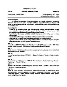
This section contains a brief description about circuitry and supporting accessories. The apparatus mainly consist of a microcontroller, IR receiver, IR transmitter, IC MAX232, USB to serial converter and battery. A 9V Lithium ion battery is used to supply power to the circuitry. LM7805 (voltage regulator) used to regulate a constant power supply of 5V to the circuitry and the microcontroller (PIC18F2550). PIC18F2550 is 28 pin, high performance, enhanced flash, USB microcontroller [8]. The CCP module of microcontroller is used to create pulse-widthmodulation (PWM). PWM is mainly responsible for modulating the IR light beam. The frequency of the PWM is depends on the value of registers of CCP module. The values of those registers are set by programming to generate the carrier frequency of 38 kHz for modulation. PWM generates on the CCP1 pin of the microcontroller which is connected to an IR LED. A 470Ω resistor is connected with the IR LED to limit the current supply. A 20 MHz crystal oscillator is also connected with the microcontroller. Full circuit diagram is presented in Fig.6. A direct 5V power supply is provided to the receiver. The output pin of the receiver is connected with RA1 pin which works as digital input to send received data into the controller. RC6/TX and RC7/RX pins are connected with MAX232 to communicate with the computer via USB to serial converter. The MAX232 is a dual driver/receiver that includes a capacitive voltage generator to supply TIA/EIA-232-F voltage levels from a single 5-V supply. Each receiver converts TIA/EIA-232-F inputs to 5-V TTL/CMOS levels [9]. MAX232 is interfaced with a USB to serial converter. USB to serial converter helps to convert a USB port to a serial communication port (COM port) as serial port is not provided in modern computers. A driver is also necessary to install in the computer for proper functioning of USB to Serial Converter.
microcontroller. Detail description about this programing algorithm is given in the following subsections. A. Interfacing with MATLAB MATLAB serial objects are used to interact with external device which is connected to the computer. At first a serial port object is created and the parameters of that object are set using serial function. Then a command is send to the device to be ready for receiving or sending data. To send data, first MATLAB manipulates the data and then write data using fprintf function by placing adequate delay in the stream of data using pause function. To receive data, first it is checked that is any data are available in the buffer. If it is then the buffer is cleared and then when data is reached, it is read from the buffer by using fread function [10].
Fig. 6. Circuit diagram of the device.
B. Interfacing with microcontroller Initially the microcontroller prepares itself for serial communication through enhanced universal synchronous asynchronous receiver transmitter (EUSART) which is a serial I/O module. TXSTA, RCSTA and BAUDCON registers control this module [8]. After assigning appropriate values into those register, controller waits for the command to send or receive data which will come through the serial port from computer. Based on this command, the device prepares itself to send or receive data. IR light beam is modulated at 38 kilo Hertz with 33% duty cycle. Equation (1) is used to calculate PWM Period (t) where TMR2T & PR2 are Timer 2 Prescale value & Timer2 period register respectively. CCP1CON register of CCP1 module is mainly control this PWM and (2) is used to calculate PWM duty cycle (R). t = [(PR2) + 1] * 4 * TOSC * (TMR2T)
(1)
R = (CCPR1L: CCP1CON) * TOSC * (TMR2T) (2) At first, data is read from the EUSART module and then some mathematical operations are performed on it to send the data as IR pulse. Let the number 159 is read from the module and (3) & (4) are used in a for loop to separate the number 159 into digits 1, 5 & 9.
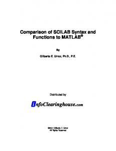
Fig. 7. Photo of the apparatus. Various parts of the apparatus are leveled on the picture.
IV.
INTERFACING AND PROGRAMMING
Programing is done at two stages in this project. Data is manipulated by MATLAB in the first stage and then in the second stage the data is fragmented and analyzed in the
digit[i] = n-{(n/10)*10}
(3)
n = n/10
(4)
Here, all the variables are integer type and in (3) variable ‘i’ is the looping variable and n = 159. We will find digit[] = [1,5,9] after computing. This means that the elements of the array ‘digit[]’ will be 1 , 5 & 9 respectively. Then corresponding time durations are calculated in microseconds (μs) for each element individually by (5). time[i] = (digit[i] * 225) + 150
(5)
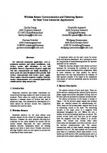
Those time durations are used as a delay to create modulated IR light beam. Transmission begins with a start bit which is followed by 3 data bits & an end bit. The length of the data bits (375, 1275 & 2175μs) are calculated by (5) for the corresponding number 1, 5 & 9 respectively. First modulated IR light is emitted for 600μs mark period as start bit and then IR LED stop blinking for 375μs space period to send the first data bit followed by 1275μs marked period to send second data bit and turned off for 2175μs as space period to send third data bit. Finally an end bit of 200μs is also added with the signal. This process is shown graphically in the Fig. 8.
Fig. 8. Data frame stucture (waveform) for sending the number 159. This graph acually represent the voltages of the pin connected to IR LED with respect to time.
Usually the output pin of the receiver is stayed high (approximately 5V). But when the receiver detects any signal/pulses, its output pin becomes low (almost 0V). For the signal send above (shown in Fig. 8), we will get the following output shown in the Fig. 9.
Fig. 10. Flowchart of the program for microcontroller
Fig. 9. The waveform that will be found at the time of receiving the number 159 is depicted here (600,375,1275,2175 & 200 μs represents Start bit,1,5,9 & End bit respectively).
In this algorithm, the apparatus takes the command from the MATLAB and it prepares itself whether it will receive or send the data according to the command. Then step by step it executes the logical & mathematical operations that were discussed above.
It is programmed that when RA1/AN1pin of the microcontroller finds low voltage, it runs a timer and a counter to measure how long the pin is stayed low. If the measured time is around 600μs, then it enters into an infinite loop otherwise it will reset the timer and counter value to zero and wait for receiving new pulse again. When voltage of the pin becomes high, we count the time to measure how long the pin stayed high and stores the counter value into a variable. Then again it put the value of the counter in another variable when the status of that pin changes from low to high. It stores the value this way for three times. Time duration is measured by analyzing the values stored in these variables. The corresponding numbers are found by applying conditional statement on the time durations. The numbers are bring together to generate the data and send it to the computer through serial port by using USART module. MATLAB serial objects pick up the data from the buffer. Flowchart of the program for microcontroller which is illustrated in Fig.10, will give more clear idea about programing algorithm.
Fig. 11. Snapshot of the whole system at the time of communicating between two computers.
V.
ERRORS AND LIMITATIONS
An average speed of 1.4 kbps is obtained by using this proposed protocol. We can easily gain a higher speed by solving some limitations of this traditional receiving module. The receiver can’t response a pulse less than 100μs. The receiver can’t detect any signal more than 10 meters away. It gives around 50% error when receive signals from the range 810 meters. Within the range 8 meters, this device can transfer data perfectly with a viewing half-angle of between 15 and 30 degrees. We can achieve higher data transfer rate by using advanced IR receiving module.
VI.
CONCLUSION
This type of wireless infrared communication systems will provide a useful complement to communication between computers, particularly for systems requiring low cost, light weight and moderate data rates in short ranges. Infrared communication is successfully competing in the market for general indoor purposes. This protocol can be used for wireless communication between computers, computer accessories & indoor home appliances in short distances. REFERENCES [1] [2]
Joseph M. Kahn, John R. Barry, “Wireless Infrared Communications”, Proceedings of the IEEE, Vol. 85, No. 2, February 1997. Y. Hiranaka, H. Sakakibara and T. Taketa, “Universal Communication Format for Multimedia Data”, Proc. of IEEE, ICCIMA 2005, 338-339, 2005.
[3]
D. Finkenthal, B. Greco, R. Halsey, L. Pena, S. Rodecker, B. Simms, R. Lee, J. Lohr, M. Schaffer and D. Schissel, “Introduction to the Electromagnetic Spectrum”, General Atomic, pp. 46, 1996. [4] B. Stuart, Infrared spectroscopy, 1st ed. Chichester, Eng.: J. Wiley, 2004. pp. 46-48 [5] David Tse,Pramod Viswanath,Fundamentals of wireless communication, Cambridge University Press, 2005.pp. 1-2. [6] D. Morris, Pulse code formats for fiber optical data communication, 1st ed. New York, CRC Press, 1983. pp- 198. [7] Jeffrey B. Carruthers, “Wireless Infrared Communications”, Wiley encyclopedia of telecommunications, 2002, USA. [8] PIC18F2455/2550/4455/4550 microcontroller datasheet, Microchip Technology Incorporated, 2006. [9] MAX232 Dual EIA-232 Drivers datasheet, Texas Instruments Incorporated, 2006. [10] Sergey E. Lyshevski, Engineering and Scientific Computations Using MATLAB, John Wiley & Sons Inc., Hoboken, New Jersey, Canada, 2003.