4.2 Per-Source Multicast: Wireless extension of DVMRP . . . . . . . 73 ..... takes advantage of inherent wireless transmission property and is very suitable for.
University of California Los Angeles
Wireless Network Multicasting A dissertation submitted in partial satisfaction of the requirements for the degree Doctor of Philosophy in Computer Science by
Ching-Chuan Chiang
1998
c Copyright by Ching-Chuan Chiang 1998
The dissertation of Ching-Chuan Chiang is approved.
Lixia Zhang
Mani B. Srivastava
Jack W. Carlyle
Mario Gerla, Committee Chair
University of California, Los Angeles 1998
ii
To my family
iii
Table of Contents
1 Introduction : : : : : : : : : : : : : : : : : : : : : : : : : : : : : : : :
1
1.1 Motivation . . . . . . . . . . . . . . . . . . . . . . . . . . . . . . .
1
1.2 Previous Work . . . . . . . . . . . . . . . . . . . . . . . . . . . .
3
1.3 Research Overview and Contributions . . . . . . . . . . . . . . . .
5
1.3.1 Network Infrastructure . . . . . . . . . . . . . . . . . . . .
5
1.3.2 Routing . . . . . . . . . . . . . . . . . . . . . . . . . . . .
6
1.3.3 Multicasting . . . . . . . . . . . . . . . . . . . . . . . . . .
6
1.3.4 Simulation and Performance Evaluation . . . . . . . . . .
7
1.4 Organization of the Dissertation . . . . . . . . . . . . . . . . . . .
7
2 Multihop, Mobile Wireless Network Infrastructure : : : : : : :
9
2.1 Cluster and Token Infrastructure . . . . . . . . . . . . . . . . . . 10 2.2 Clustering (Least Clusterhead Change (LCC) Algorithm) . . . . . 12 2.3 MAC layer (Token Scheduling Channel Access Scheme) . . . . . . . 15 2.4 Gateway Code Scheduling (GCS) . . . . . . . . . . . . . . . . . . 16 2.5 Routing Protocols . . . . . . . . . . . . . . . . . . . . . . . . . . . 17 2.6 MAC and Routing Experiments . . . . . . . . . . . . . . . . . . . 20 2.6.1 Mobility Model . . . . . . . . . . . . . . . . . . . . . . . . 20 2.6.2 Simulation Parameters . . . . . . . . . . . . . . . . . . . . 21 2.6.3 Performance Evaluation . . . . . . . . . . . . . . . . . . . 22
3 Multicasting with RP : : : : : : : : : : : : : : : : : : : : : : : : : : 25 iv
3.1 Core Based Tree Multicast . . . . . . . . . . . . . . . . . . . . . . 25 3.1.1 Multicast Tree graft and prune . . . . . . . . . . . . . . . 26 3.1.2 Multicast Tree recon guration . . . . . . . . . . . . . . . . 27 3.1.3 Simulation & Performance Evaluation . . . . . . . . . . . . 29 3.2 Hard State versus Soft State Tree Maintenance . . . . . . . . . . 34 3.2.1 Hard State Protocol . . . . . . . . . . . . . . . . . . . . . 35 3.2.2 Soft State Protocol . . . . . . . . . . . . . . . . . . . . . . 37 3.2.3 Simulation & Performance Evaluation . . . . . . . . . . . . 38 3.3 RP Tree Multicast Strategies . . . . . . . . . . . . . . . . . . . . 45 3.3.1 Shared Tree Multicast . . . . . . . . . . . . . . . . . . . . 49 3.3.2 Adaptive Tree Multicast . . . . . . . . . . . . . . . . . . . 51 3.3.3 Per-Source Tree Multicast . . . . . . . . . . . . . . . . . . 54 3.3.4 RP Dynamic Relocation . . . . . . . . . . . . . . . . . . . 55 3.3.5 Simulation & Performance Evaluation . . . . . . . . . . . . 59
4 Multicasting without RP : : : : : : : : : : : : : : : : : : : : : : : : 71 4.1 Flooding . . . . . . . . . . . . . . . . . . . . . . . . . . . . . . . . 71 4.1.1 Reverse Path Forwarding (RPF) . . . . . . . . . . . . . . . 72 4.1.2 Packet ID duplicate detection . . . . . . . . . . . . . . . . 73 4.2 Per-Source Multicast: Wireless extension of DVMRP . . . . . . . 73 4.2.1 Leaf Node Detection . . . . . . . . . . . . . . . . . . . . . 74 4.2.2 Dynamic Grafting/Pruning . . . . . . . . . . . . . . . . . 75 4.2.3 RPF vs. Packet ID duplicate detection . . . . . . . . . . . 77
v
4.2.4 Protocol Overhead . . . . . . . . . . . . . . . . . . . . . . 78 4.3 Forwarding Group Multicast Protocol (FGMP) . . . . . . . . . . 79 4.3.1 FG Maintenance via Receiver Advertising (FGMP-RA) . . 83 4.3.2 FG Maintenance via Sender Advertising (FGMP-SA) . . . 84 4.3.3 Protocol Overhead . . . . . . . . . . . . . . . . . . . . . . 85 4.4 Simulation Environment & Performance Evaluation . . . . . . . . 86 4.4.1 Simulation Environment . . . . . . . . . . . . . . . . . . . 86 4.5 Performance Evaluation . . . . . . . . . . . . . . . . . . . . . . . 87 4.5.1 Throughput & E�ciency . . . . . . . . . . . . . . . . . . . 87 4.5.2 Forwarding Group Size . . . . . . . . . . . . . . . . . . . . 89 4.5.3 Channel & Storage Overhead . . . . . . . . . . . . . . . . 89 4.5.4 Light Load Tra�c Performance . . . . . . . . . . . . . . . 92
5 On-Demand Multicast : : : : : : : : : : : : : : : : : : : : : : : : : 95 5.1 Motivation . . . . . . . . . . . . . . . . . . . . . . . . . . . . . . . 95 5.2 On-Demand Routings . . . . . . . . . . . . . . . . . . . . . . . . . 97 5.3 On-Demand FGMP . . . . . . . . . . . . . . . . . . . . . . . . . . 100 5.3.1 On-Demand Request phase . . . . . . . . . . . . . . . . . 100 5.3.2 Next hop Recovery phase . . . . . . . . . . . . . . . . . . . 101 5.3.3 Refresh Strategy . . . . . . . . . . . . . . . . . . . . . . . 103 5.3.4 Optimal next hops . . . . . . . . . . . . . . . . . . . . . . 104 5.4 Simulation & Performance Evaluation . . . . . . . . . . . . . . . . 105 5.4.1 Performance Evaluation . . . . . . . . . . . . . . . . . . . 106
vi
5.4.2 Channel Utilization . . . . . . . . . . . . . . . . . . . . . . 107 5.4.3 Storage Overhead . . . . . . . . . . . . . . . . . . . . . . . 110 5.4.4 Throughput & E�ciency . . . . . . . . . . . . . . . . . . . 111 5.4.5 Forwarding Group Size . . . . . . . . . . . . . . . . . . . . 112 5.4.6 Delay & Hops . . . . . . . . . . . . . . . . . . . . . . . . . 113
6 Reliable Multicast : : : : : : : : : : : : : : : : : : : : : : : : : : : : 116 6.1 The Reliable Multicast Problem . . . . . . . . . . . . . . . . . . . 117 6.2 Scalable Reliable Multicast (SRM) . . . . . . . . . . . . . . . . . 117 6.2.1 Session Messages . . . . . . . . . . . . . . . . . . . . . . . 118 6.2.2 Loss Recovery Algorithm . . . . . . . . . . . . . . . . . . . 119 6.3 FGMP + SRM . . . . . . . . . . . . . . . . . . . . . . . . . . . . 120 6.4 Unicast patching for FGMP-RA . . . . . . . . . . . . . . . . . . . 121 6.5 Simulation & Performance Evaluation . . . . . . . . . . . . . . . . 122 6.5.1 Performance Evaluation . . . . . . . . . . . . . . . . . . . 122
7 Conclusions and Future Work : : : : : : : : : : : : : : : : : : : : : 128 7.1 On-demand and Hierarchical Multicast . . . . . . . . . . . . . . . 129 7.2 Quality of Service (QoS) and RSVP . . . . . . . . . . . . . . . . . 129 7.3 Wireless Multicast Flow Control . . . . . . . . . . . . . . . . . . . 129 7.4 Reliable Multicast . . . . . . . . . . . . . . . . . . . . . . . . . . . 130
A RP Trees Multicast Protocols : : : : : : : : : : : : : : : : : : : : : 131 A.1 Shared Tree Multicast : Unicast Sender Mode . . . . . . . . . . . 132
vii
A.2 Shared Tree Multicast : Multicast Sender Mode . . . . . . . . . . 133 A.3 Adaptive Tree multicast . . . . . . . . . . . . . . . . . . . . . . . 134 A.4 Examples of RP Dynamic Relocation . . . . . . . . . . . . . . . . 136
B FGMP Protocols : : : : : : : : : : : : : : : : : : : : : : : : : : : : : 140 B.1 FGMP-RA . . . . . . . . . . . . . . . . . . . . . . . . . . . . . . . 140 B.2 On-Demand FGMP: Join Request . . . . . . . . . . . . . . . . . . 141
Bibliography : : : : : : : : : : : : : : : : : : : : : : : : : : : : : : : : : 144
viii
List of Figures 2.1 Cluster changes vs. Transmission Power . . . . . . . . . . . . . . 13 2.2 Clustering among 100 hosts, Transmission Power=120 . . . . . . . 14 2.3 Average delay of CGSR+PTS+GCS with multiple radio . . . . . 17 2.4 Routing examples (from node 1 to node 11) . . . . . . . . . . . . 18 2.5 Mobility Model . . . . . . . . . . . . . . . . . . . . . . . . . . . . 20 2.6 Throughput of CGSR� and DSDV . . . . . . . . . . . . . . . . . 24 3.1 Performance comparison of ACK tree and REQ tree . . . . . . . . 27 3.2 Loop example . . . . . . . . . . . . . . . . . . . . . . . . . . . . . 29 3.3 Initial multicast tree . . . . . . . . . . . . . . . . . . . . . . . . . 30 3.4 Recon g. & control pkts vs group size . . . . . . . . . . . . . . . . 31 3.5 Total # of transient loops . . . . . . . . . . . . . . . . . . . . . . 32 3.6 Recon g. & control pkts vs group size . . . . . . . . . . . . . . . . 33 3.7 Control packet O/H . . . . . . . . . . . . . . . . . . . . . . . . . . 34 3.8 Average JOIN latency . . . . . . . . . . . . . . . . . . . . . . . . 35 3.9 Soft State: impact of Trefresh and mobility . . . . . . . . . . . . . 40 3.10 Ttimeout = N * Trefresh @ mobility = 0.45 km/hr . . . . . . . . . . 41 3.11 Trefresh @ mobility = 0.45 km/hr . . . . . . . . . . . . . . . . . . 41 3.12 Ttimeout = N * Trefresh @ mobility = 72 km/hr . . . . . . . . . . . 42 3.13 Trefresh @ mobility = 72 km/hr . . . . . . . . . . . . . . . . . . . 42 3.14 Join Latency . . . . . . . . . . . . . . . . . . . . . . . . . . . . . 44 3.15 Control Messages . . . . . . . . . . . . . . . . . . . . . . . . . . . 45 ix
3.16 Throughput . . . . . . . . . . . . . . . . . . . . . . . . . . . . . . 46 3.17 Example of unicast sender mode . . . . . . . . . . . . . . . . . . . 50 3.18 Example of multicast sender mode . . . . . . . . . . . . . . . . . 50 3.19 Examples of adaptive tree multicast . . . . . . . . . . . . . . . . . 53 3.20 Examples of per-source tree multicast . . . . . . . . . . . . . . . . 54 3.21 Heavy load experiments; uniform mobility . . . . . . . . . . . . . 63 3.22 Light load; uniform mobility . . . . . . . . . . . . . . . . . . . . . 65 3.23 Heavy load; 2-level mobility . . . . . . . . . . . . . . . . . . . . . 66 3.24 Light load; 2-level mobility . . . . . . . . . . . . . . . . . . . . . . 67 3.25 Light load; 2-level mobility (only senders move) . . . . . . . . . . 68 3.26 Performance Evaluation . . . . . . . . . . . . . . . . . . . . . . . 70 4.1 Example of upstream change . . . . . . . . . . . . . . . . . . . . . 76 4.2 Throughput of adaptive vs. non-adaptive DVMRP . . . . . . . . 77 4.3 Throughput of DVMRP . . . . . . . . . . . . . . . . . . . . . . . 79 4.4 An example of FGMP . . . . . . . . . . . . . . . . . . . . . . . . 80 4.5 Example of Forwarding tables (FGMP-RA) . . . . . . . . . . . . . 85 4.6 Throughput . . . . . . . . . . . . . . . . . . . . . . . . . . . . . . 89 4.7 Performance of Flooding, DVMRP, and FGMP (Type 1, Load A)
90
4.8 Forwarding Group Size comparison . . . . . . . . . . . . . . . . . 91 4.9 Control Channel Overhead . . . . . . . . . . . . . . . . . . . . . . 92 4.10 Multicast Storage O/H (Type 2 con guration) . . . . . . . . . . . 93 4.11 Performance in Light Load Multicast Tra�c (mean = 50 ms) . . . 94
x
5.1 Channel Usage by RTU . . . . . . . . . . . . . . . . . . . . . . . . 97 5.2 Total number of transmissions of RTU . . . . . . . . . . . . . . . 97 5.3 An example of On-Demand Routing . . . . . . . . . . . . . . . . . 99 5.4 Example of Forwarding tables for FGMP-RA . . . . . . . . . . . . 106 5.5 Channel Utilization of FGMP-SA (Bellman-Ford) [One-to-Many] . . . . . . 108 5.6 Channel Utilization of FGMP-SA (On-Demand) [One-to-Many] . . . . . . . 108 5.7 Control Messages of FGMP-SA (Bellman-Ford) [One-to-Many] . . . . . . . 109 5.8 Control Messages of FGMP-SA (On-Demand) [One-to-Many] . . . . . . . . 109 5.9 Throughput [One-to-Many] . . . . . . . . . . . . . . . . . . . . . . . 110 5.10 Multicast E�ciency [One-to-Many] . . . . . . . . . . . . . . . . . 110 5.11 Size of Forwarding Group (jFGj) [One-to-Many] . . . . . . . . . . . 112 5.12 Average number of RTE [One-to-Many] . . . . . . . . . . . . . . . . 112 5.13 Average Delay [One-to-Many] . . . . . . . . . . . . . . . . . . . . . . . 113 5.14 Average Hops [One-to-Many] . . . . . . . . . . . . . . . . . . . . . . . 113 5.15 Throughput [One-to-Many] . . . . . . . . . . . . . . . . . . . . . . . 114 5.16 Average number of RTE [Many-to-Many] . . . . . . . . . . . . . . . 114 5.17 Throughput [Many-to-Many] . . . . . . . . . . . . . . . . . . . . . . . 115 5.18 Average Delay [Many-to-Many] . . . . . . . . . . . . . . . . . . . . . . 115 6.1 SRM Loss Recovery: upon hearing B's response to A's request, S does not respond. . . . . . . . . . . . . . . . . . . . . . . . . . . . 119 6.2 Performance Evaluation of SRM . . . . . . . . . . . . . . . . . . . 123 6.3 Patch O/H . . . . . . . . . . . . . . . . . . . . . . . . . . . . . . 124
xi
6.4 Performance Measure of Patch . . . . . . . . . . . . . . . . . . . . 125 6.5 Patch Comparison of SRM vs. Unicast Patching . . . . . . . . . . 126 6.6 Patch Comparison of SRM vs. Unicast Patching (2-level Mobility) 127 A.1 Examples of multicast protocols . . . . . . . . . . . . . . . . . . . 136 A.2 Total Length . . . . . . . . . . . . . . . . . . . . . . . . . . . . . 137 A.3 Max Height . . . . . . . . . . . . . . . . . . . . . . . . . . . . . . 138 A.4 Total Link . . . . . . . . . . . . . . . . . . . . . . . . . . . . . . . 139
xii
List of Tables 2.1 Simulation Topology and Parameters . . . . . . . . . . . . . . . . 22 3.1 parameters of higher throughput . . . . . . . . . . . . . . . . . . . 43 4.1 Re ooding period . . . . . . . . . . . . . . . . . . . . . . . . . . . 78 4.2 Format of join request packet . . . . . . . . . . . . . . . . . . . . 82 4.3 Format of member table at the sender . . . . . . . . . . . . . . . 83 4.4 Format of forwarding table FW . . . . . . . . . . . . . . . . . . . 84 4.5 Multicast Tra�c Load . . . . . . . . . . . . . . . . . . . . . . . . 87 5.1 Format On-Demand routing table entry . . . . . . . . . . . . . . . 102 5.2 Format of on-demand join request/sender info packet . . . . . . . 102 5.3 Routing table of node 12 for gure 4.5 . . . . . . . . . . . . . . . 105 5.4 Routing table of node 12 for gure 5.4 . . . . . . . . . . . . . . . 105 5.5 Routing table of node 12 with next hop list . . . . . . . . . . . . . . 105 5.6 Soft state parameters . . . . . . . . . . . . . . . . . . . . . . . . . 107
xiii
Acknowledgments I owe the deepest gratitude to Professor Mario Gerla, my advisor, for his guidance, support, and kindness throughout my years at UCLA. He motivated and inspired me during every stage of the writing process. I am thankful to Professor Lixia Zhang who provided me with additional advice and insights into several aspects of this thesis. I would like to thank Professor Jack Carlyle and Mani Srivastava for their patience and willingness to be on my committee. I greatly thank Professor Mani Srivastava for agreeing to be on my committee at an extremely short notice. I am grateful to Professor Jack Carlyle for his help during my rst year at UCLA. I am indebted to many friends and colleagues (Jei-Chen Wu, Winston Liu, Tsuwei Chen, Ronn Ritke, William Su, Hsiao-Kuang Wu, Guangyu Pei, Gurpreet Multani, and James Stepane) for their contributions to my work. Finally, the acknowledgments would not be complete without mention of my wife, Ya-Ching Wang, whose encouragement and love has always supported me during my most productive period, and of my parents whose faithful support has continued over the years. This research has been supported by the fellowship from Chung-Cheng Institute of Technology.
xiv
Vita 1964
Born, PingTung, Taiwan, R.O.C.
1983{1987
B.S. (Applied Mathematics), Chung-Cheng Institute of Technology, TaoYuan, Taiwan, R.O.C.
1987{1989
Teaching Assistant, Computer Science Department, ChungCheng Institute of Technology, TaoYuan, Taiwan, R.O.C.
1989{1991
M.S. (Computer Science and Information Engineering), National Taiwan University, Taipei, Taiwan, R.O.C.
1991{1994
Instructor, Computer Science Department, Chung-Cheng Institute of Technology, TaoYuan, Taiwan, R.O.C.
1994{present
Ph.D, Computer Science Department, UCLA.
xv
Publications
Ching-Chuan Chiang, Mario Gerla and Lixia Zhang, \Forwarding Group Multicast Protocol (FGMP) for Multihop, Mobile Wireless Networks", in Special Issue of Cluster Computing: the Journal of Networks, Software Tools and Applications, Vol. 1, No. 2, 1998.
Ching-Chuan Chiang and Mario Gerla, \Routing and Multicast in Multihop, Mobile Wireless Networks", in IEEE International Conference on Universal Personal Communications (ICUPC'97), San Diego, California, 1997.
Ching-Chuan Chiang, Mario Gerla and Lixia Zhang \Shared Tree Wireless Network Multicast", in IEEE 6th International Conference on Computer Communications and Networks (ICCCN'97), Las Vegas, Nevada, 1997.
Ching-Chuan Chiang, Eric Hsiao-Kuang Wu, Winston Liu, and Mario Gerla, \Routing in Clustered Multihop, Mobile Wireless Networks with fading channel", in The IEEE Singapore International Conference on Networks (SICON97), Singapore, 1997.
Ching-Chuan Chiang and Mario Gerla, \Routing in Clustered Multihop, Mobile Wireless Networks", in Proceedings of 11th International Conference on Information Networking (ICOIN11), Taipei, Taiwan, R.O.C., 1997. Winston Liu, Ching-Chuan Chiang, Hsiao-Kuang Wu, Vikas Jha, Mario Gerla
xvi
and Rajive Bagrodia, \Parallel Simulation Environment for Mobile Wireless Networks", in 1996 Winter Simulation Conference Proceedings (WSC'96), San Diego, CA, 1996.
xvii
Abstract of the Dissertation
Wireless Network Multicasting by
Ching-Chuan Chiang
Doctor of Philosophy in Computer Science University of California, Los Angeles, 1998 Professor Mario Gerla, Chair Wireless networks provide mobile users with ubiquitous communicating capability and information access regardless of location. Conventional ground radio networks are the \last hop" extension of a wireline network, thus supporting only single hop communications within a \cell". In this dissertation we address a novel type of wireless networks called \multihop" networks. As a di�erence from \single hop" (i.e., cellular) networks which require xed base stations interconnected by a wired backbone, multihop networks have no xed based stations nor a wired backbone. The main application for mobile wireless multihopping is rapid deployment and dynamic recon guration. When the wireline network is not available, as in battle eld communications and search and rescue operations, multihop wireless networks provide the only feasible means for ground communications and information access. Multihopping poses several new challenges in the design of wireless network protocols. We focus on multicasting in this thesis. The multicast service is critical in applications characterized by the close collaboration of teams (e.g., rescue patrol, battalion, scientists, etc.) with audio/video conferencing requirements and sharing of text and images. Multicasting in a multihop wireless network is much more complex than in cellular wireless xviii
networks where all mobiles in a cell can be reached in a single hop. In fact, one or more multicast structures (e.g., trees) are maintained in the multihop network to e�ciently deliver packets from sources to destinations in the multicast group. Multicast solutions similar to those used in mesh wireline networks such as the Internet might be considered. Yet, these solutions are not directly applicable to wireless networks because of the mobility of the users and the dynamically changing topology. In this dissertation we evaluate various popular multicast protocols via simulations and propose new protocols which are well suitable for multihop networks. This dissertation mainly covers ve areas: (1) Cluster-Token infrastructure and cluster routing; (2) Shared tree wireless multicast routing protocols; (3) Wireless multicast routing without Rendezvous Points; (4) On-demand wireless multicast; (5) Reliable wireless multicast.
xix
CHAPTER 1 Introduction 1.1 Motivation Data transmission between multiple senders and receivers is becoming increasingly important in today's networks. There are many applications for sending data from a single source to multiple destinations (e.g., audio/video broadcasting), or from multiple senders to multiple receivers (e.g., teleconference). Multicasting reduces the communication costs for applications that send the same data to multiple recipients. Instead of sending data via multiple unicasts, multicasting minimizes the link bandwidth consumption, sender and router processing, and delivery delay. In addition, multicasting provides a simple and robust communication mechanism when the receivers' individual addresses are unknown or changeable. In wireless networks, it is very important to reduce transmission overhead and power consumption, due to the limitation of the wireless channel. Multicasting can improve the utilization of the wireless link when sending multiple copies of messages, and exploit the inherent broadcast property of wireless transmission. Each multicast group has a unique multicast identi er. Each multicast address identi es a host group [CD85], namely a group of hosts that should receive a packet sent to that address. Membership management protocols, e.g., IGMP [Dee89], provide the membership information for data forwarding. The multicast group maintenance protocols should be adaptive to the dynamic change
1
of the group membership. Such management protocols are especially important and challenging in a mobile environment because group members need to be traced. This dissertation covers the topic of multicast, speci cally for wireless networks. Wireless terrestrial networks provide mobile users with ubiquitous communicating capability and information access regardless of the location. Broadly speaking, we can de ne two types of wireless networks: (a) cellular networks, and (b) instant infrastructure, multihop networks. In cellular radio networks [TIA92, Goo90] mobile users communicate in a single hop with a base station, which is in turn connected to a wired backbone. In multihop wireless networks, in contrast, there are no xed base stations. Transmissions to the intended destination must travel one or more wireless hops. The main application of wireless multihop networks is rapid deployment in areas where there is no wired infrastructure (e.g., the battle eld) or where the infrastructure has failed (e.g., earthquake, re, ood relief, etc.). Examples of multihop implementations are ad-hoc networks [Joh94, PB94] and packet radio networks [CE95, JT87]. Multihopping poses new challenges in wireless network protocol design. For example, mobile-IP routing protocols developed for cellular-type networks [IDJ91] cannot be directly applied to the multihop case since there is no xed home agent to serve as routing reference. Multicasting, in particular, is very challenging in a multihop environment. Again, traditional wired network multicast protocols [BFC93, DC90] cannot be directly applied to this environment. For example, in the Internet multicast backbone (MBone) application, the multicast protocol DVMRP [DC90] uses the reverse path forwarding (RPF) protocol to deliver multicast packets. In reverse path forwarding, a router forwards a broadcast packet originating at source S if and only if it has arrived via the shortest
2
path to S . If source S moves rapidly, it is possible that its packet arrives from a direction di�erent than indicated by the the local routing table (which has not yet been updated). Thus, the router will fail to forward the packet [ABB96]. In addition, periodic full broadcasts in DVMRP introduce costly overhead on the low bandwidth wireless channel and is not suitable for a sparsely distributed membership. Mobility is clearly the main challenge in wireless multicast, posing the following problems: (a) sources move, making source-oriented protocols ine�cient; (b) multicast group members move, thus requiring an easily recon gurable multicast tree topology; (c) transient loops may form during tree recon guration; (d) channel overhead caused by tree recon guration updates tends to increase very rapidly with mobility, network size and membership size.
1.2 Previous Work In wired network such as the Internet, there are two popular wired network multicast schemes: per-source shortest tree and shared tree. The per-source tree scheme consists of broadcasting the packet from the source to all destinations along the source tree using \reverse path forwarding". An arbitrary network node will accept the packet broadcast by source S as long as the packet is received from the shortest path emanating from S . This provision is required in order to avoid endless looping. Examples of per-source tree multicast protocols are DVMRP [DC90] and PIM dense mode [DEF97]. Per-source tree multicasting has many attractive properties. To begin, the shortest tree information from each source to all destinations generally comes for free since it is embedded in the routing tables of the most common routing algorithms such as Distance Vector and Link State. Furthermore, source tree multicast distributes the tra�c evenly 3
in the network (assuming that sources and receivers are evenly distributed); it requires minimal initialization and maintenance; and it does not rely on a central control point (e.g., rendezvous point). In mobile networks, however, the persource tree approach presents a problem. Suppose a source moves faster than the routing tables can track it. In this case, some of the nodes have obsolete routing tables which point in the \wrong direction". Following the \reverse path forwarding" principle, multicast packets are dropped at such nodes and may never reach some of the receivers. Another popular wired network scheme is shared-tree multicast. In this scheme, a single tree rooted at a Rendezvous Point (RP ) is maintained (instead of many per-source trees). Examples of shared-tree approach are CBT [BFC93, CZ95] and PIM sparse mode [DEF96]. The shared tree is less sensitive to source mobility and can in part overcome the above mentioned fast moving source problem. Namely, a very fast source will send its packet to the RP in unicast mode. Packets are correctly delivered to the RP on the shortest paths, irrespective of the speed of the source. The RP will then multicast the packet on the shared tree to the intended destinations. This works as long as the shared tree is stable. If ALL the nodes are moving fast (relative to routing table updates), the shared tree solution also fails. Some wireless multicast protocols have been proposed [ABB96, CB95, PR97]. Protocol of [ABB96] modi es IP multicast and is designed for single hop wireless networks. The scheme proposed in [CB95] is a RP -based multicast combining resource reservation and admission control. A link level reliable broadcast scheme, per-source tree based, is studied in [PR97], which is able to provide reliable broadcast services to all members and is more exible than spanning tree and more e�cient than ooding.
4
1.3 Research Overview and Contributions Most multicast protocols work well with static networks. However, to support an e�cient and adaptive multicasting for a very dynamic network (especially multihop) is very challenging. In this dissertation we work on this \ad-hoc" network and evaluate various existing multicast schemes. New multicast strategies are proposed to achieve better performance. Protocol evaluations are performed via a detailed simulator which provides an exible way to verify and monitor the protocol behavior.
1.3.1 Network Infrastructure The infrastructure proposed in this dissertation is a clustered multihop infrastructure [CWL97, GT95]. A number of mobile nodes are grouped into a cluster according to a distributed clustering algorithm. Clustering provides an e�cient access control for wireless channel and spatial reuse, which increases the capacity and the utilization of a wireless channel. We propose a clustering scheme (LCC) which has better stability than previous clustering schemes, and thus provides a more stable infrastructure for upper layer protocols such as routing and multicasting. Within a cluster, the channel access is controlled by a token which is scheduled by the clusterhead. Nodes are moving based on a three-state Markov chain probability model. The cluster structure is automatically maintained according to the clustering algorithm when nodes move and topology changes. The clusterhead monitors and schedules the token. A new token is created when the clusterhead detects a token loss. A 2-level mobility model is used to improve the scalability of cluster and/or multicast structure in some experiments, where nodes are subdivided in two classes, slow and fast, at network initialization.
5
1.3.2 Routing Most multicast protocols are designed independent of the underlying routing scheme. Some multicast schemes like DVMRP need routing information to detect the duplicate packets and to direct packet forwarding. A distance vector type routing protocol, Destination-Sequenced Distance-Vector (DSDV), is used for most experiments. DSDV has the same complexity as Bellman-Ford or RIP, but with better protection against loops. A hierarchical cluster routing protocol has been proposed to take advantage of the cluster-token infrastructure. On-demand routing strategies are also exploited for supporting on-demand multicasting.
1.3.3 Multicasting The major focus of this dissertation is on the multicasting for wireless networks. Various existing multicast protocols have been studied to explore their problems in mobile wireless networks. Variants of CBT, DVMRP, and PIM are modi ed in order to apply to our infrastructure. Two multicast maintenance schemes, soft state and hard state, are evaluated for mobile environments. The soft state scheme is more exible and e�cient than the hard state scheme and adapts well with mobility, making it very suitable for dynamically changing environments. A new multicast protocol, FGMP, is proposed for mobile wireless networks. FGMP takes advantage of inherent wireless transmission property and is very suitable for dynamic network topologies. The forwarding group concept is adopted in FGMP which maintains and forwards multicast tra�c based on forwarding nodes rather than on multicast tree links like most multicast schemes. We also propose an On-Demand multicast which uses on-demand routing to reduce the storage and channel overhead of routing tables. Without routing table updates, on-demand multicast is able to scale well with increasing network and multicast member size. 6
In addition, on-demand multicast achieves better performance at high mobility. Reliable multicast, which provides a con dential delivery of multicast packets, is very important for the wireless channel. An application level reliable multicast strategy, SRM, has been adopted and simulated with FGMP.
1.3.4 Simulation and Performance Evaluation In order to evaluate the performance of various protocols, a simulator based on a parallel simulation language, Maisie, has been developed. The Maisie simulation environment has been implemented on a variety of workstation systems (SunOs, Solaris, and Linux etc.), on distributed memory multiprocessor systems like IBM/SP2, and on a shared memory system (Sparc 1000). This simulator provides a fancy graphic interface which is very useful in debugging, verifying, and re ning the protocols. Statistical values for the simulation are collected to measure the performance. The performance metrics include throughput, duplicate packets, average delay, average hops, loss rate, channel overhead, and storage overhead.
1.4 Organization of the Dissertation This dissertation focuses on the multicast protocol design and performance evaluation for multihop, mobile wireless networks. In chapter 2, we present the network infrastructure we envision; clustering, MAC scheme, and routing strategies are described as well. Chapter 3 discusses multicast protocols using Rendezvous Point(s). Shared tree multicast schemes belong to this category. An adaptive multicast scheme is proposed for mobile environments. Per-source tree multicast schemes and multicasting without a Rendezvous Point are studied in chapter 4,
7
and. FGMP is described and compared with other schemes. Chapter 5 introduces the On-demand multicast and shows the performance results. Chapter 6 addresses the Scalable Reliable Multicast (SRM) [FJM95] and presents the implementation on our simulator. Chapter 7 contains the conclusions and directions for future research.
8
CHAPTER 2 Multihop, Mobile Wireless Network Infrastructure Wireless networks provide mobile users with ubiquitous communicating capability and information access regardless of the location. Cellular networks [TIA92, Goo90] or personal communication services (PCS) [LCN95] provide mobile users with continuous network connectivity under the coverage of base stations (sometimes called Mobile Support Stations, MSS, or Mobility Support Routers, MSR). Mobile users communicate directly via wireless channel with base stations which are interconnected by a wired backbone (single hop). The network architecture under study is a wireless, mobile, multihop architecture. Unlike cellular or PCS systems, there are no xed base stations connected by a wireline network. All nodes communicate via wireless channel with possible multihopping over several mobile stations. The main motivation for mobile wireless multihopping is rapid deployment and dynamic recon guration. When the wireline network is not available, as in battle eld communications and search and rescue operations, multihop wireless networks provide the only feasible means for ground communications and information accesses. Examples of such networks are ad-hoc networks [Joh94, PB94] and packet radio networks [CE95, JT87]. The dynamic feature in multihop mobile wireless networks leads to the problem of keeping track of the topology connectivity [PB94]. The network protocols such as MAC layer
9
(channel access), routing, multicasting, etc., are more complicated than single hop wireless networks. There have been various protocols proposed during the past years [GT95, LG95, Lin96]. This research focuses on multicast in multihop, mobile wireless networks. The network infrastructure, MAC layer, and routing strategies are introduced in this chapter.
2.1 Cluster and Token Infrastructure The aggregation of nodes into clusters under clusterhead control provides a convenient framework for the development of e�cient protocols both at the MAC layer (e.g., code separation among clusters, channel access, bandwidth allocation) and at the network layer (e.g., hierarchical routing) [GT95]. At the MAC layer, the main objective of clustering is e�cient use of the medium, while at the network layer the hierarchical routing induced by clustering provides scalability and robustness to mobility. In our distributed clustering algorithm, nodes are elected as clusterheads based on preferential criteria (e.g., lowest ID number, etc.). All nodes within transmission range of a clusterhead belong to the same cluster. That is, all nodes in a cluster can communicate directly with a clusterhead and (possibly) with each other. Nodes belonging to more than one cluster are called gateways. Gateways support communications between adjacent clusters. Clustering provides an e�ective way to allocate wireless channels among di�erent clusters. Across clusters, we enhance spatial reuse by using di�erent spreading codes (i.e. CDMA [GJ91]). Within a cluster, we use a clusterhead controlled token protocol (i.e. polling) to allocate the channel among competing nodes. The token approach allows us to give priority to clusterheads in order to maximize channel utilization and minimize delay. A clusterhead should get more chances to transmit because it is in charge of broadcasting within the cluster and 10
of forwarding messages between mobile hosts which are not "connected". The channel access scheme is as follows: 1: Initially, the clusterhead gets the permission token to access the radio channel. It transmits any messages it has in its transmission queue. 2: The clusterhead passes the token to one of its neighbors according to a separately de ned scheduling algorithm. 3: The cluster node (regular node2 ) or gateway returns the token to its clusterhead after it has transmitted its message(s) (if any). 4: Repeat 1 to 3. For each cluster only one node, which gets the permission token, can access the channel with an assigned code (CDMA). In some cases the permission token may be lost. Such a case occurs when the node with the permission token moves outside the cluster. Another case is when the host is a gateway. The gateway might be tuned to a di�erent code (i.e. di�erent cluster), thus missing the permission token which is then lost. To overcome these problems, the clusterhead reissues the permission token after timeout. We can use a heuristic token scheduling algorithm (described in section 2.3) to choose the next neighbor host to get more e�cient channel utilization and message delivery performance. Also we can reserve some channel accesses (more chances) for real time or multimedia tra�cs. Polling was chosen here for several reasons. First, polling is consistent with the IEEE 802.11 standard (Point Coordination Function) [CWK97]. Secondly, polling gives priority to the clusterhead, which is desirable since routes are forced 2
A regular node is a node which is neither a clusterhead nor a gateway
11
to go through clusterheads in the 2-level cluster routing. Third, polling permits easy support of real time connections (which can be scheduled at periodic intervals by the clusterhead). Fourth, in our experiments each cluster has on average six neighbors (which is the optimal value in a uniform multihop architecture [KS78]); thus polling latency is not a critical concern. For larger cluster size the polling scheme can be replaced by a polling/random access scheme, to reduce latency. This is accomplished by de ning a two phase cycle. In the rst phase, the clusterhead transmits its packets and polls nodes with real time connections; in the second phase, backlogged nodes access the channel using the CSMA/CA protocol [Kar90]. This latter scheme is also consistent with IEEE 802.11 (Distributed Coordination Function). In this thesis we only consider polling for simplicity.
2.2 Clustering (Least Clusterhead Change (LCC) Algorithm) In a mobile network, an important criterion in cluster algorithm design is stability. Frequent clusterhead changes adversely a�ect the performance of other protocols such as scheduling and allocation. In our clustering algorithm (Least Cluster Change (LCC) clustering algorithm), only two conditions cause the clusterhead to change. One is when two clusterheads come within range of each other, and the other is when a node becomes disconnected from any other cluster. This is an improvement (in stability) over existing algorithms which select the clusterhead every time the cluster membership changes. Following is our clustering algorithm speci cation. 1 : At the start we use lowest-id cluster algorithm or highest-connectivity cluster algorithm to create initial clusters. 12
Number of clusterhead changes
70000 highest-connectivity lowest-id LCC-highest-connectivity LCC-lowest-id
60000 50000 40000 30000 20000 10000 0 0
100 200 300 400 500 600 700 800 900 1000 Transmission Power (meter)
Figure 2.1: Cluster changes vs. Transmission Power 2 : When a non-clusterhead node in cluster i move into a cluster j , no clusterhead in cluster i and j will be changed (only cluster members are changed). 3 : When a non-clusterhead node moves out of its cluster(s) and does not enter into any existing cluster, it becomes a new clusterhead, forming a new cluster. 4 : When clusterhead C (i) from cluster i moves into the cluster j , it challenges the corresponding clusterhead C (j ). Either C (i) or C (j ) will give up its clusterhead position according to lowest-id or highest-connectivity (or some other well de ned priority scheme). 5 : Nodes which become separated from a cluster will recompute the clustering according to lowest-id or highest-connectivity. Figure 2.1 shows that LCC further reduces clusterhead changes with respect to the existing schemes. We note that using LCC with lowest-id or highestconnectivity as the underlying mechanism does not make much di�erence. 13
Figure 2.2 shows an example of clustering using LCC with lowest-id among 100 nodes. clusterhead gateway regular node
79 39 09
89
69 59
49
19
99
78
29
98
88
38
08 18 28
57 36
67
1526 25
55
45
84
65
94 83
64
54
1324
93
44 53
33
02
74 63
23 12
22
82 62 73
52
91
31
11
81 61
21
00
41 20 30
92
43
32 42
10
95
75 34
01
85
35
14
03
76
66 46
96
86
56
05
04
87
77
47
27
16
97
37
17
06
68
58
48
07
40
50
51 60
72 71 80
90
70
Figure 2.2: Clustering among 100 hosts, Transmission Power=120 One may also introduce the \preferential" condition that clusterheads are chosen among \slow moving" nodes. This way, the stability of hierarchical routing (and, consequently, of the forwarding group) is greatly improved. Beside the clusterhead election, additional procedures are required to manage clusters. For example, if spreading codes are used, the nodes must agree on a common control 14
code for initialization and for recon guration [GT95]; and on the selection of orthogonal codes in adjacent clusters, etc. Cluster maintenance protocols run continuously in the background in order to adjust to node movements and dynamically recon gure the cluster structure accordingly. Average convergence time of the clusterhead election algorithm is O(1), that is, it does not depend on network size N and thus scales well [GT95]. In fact, clusters are recon gured as quickly as links are added/deleted. This property implies that the convergence of the routing algorithm (which operates above clustering) is not \slowed down" by the presence of clusters.
2.3 MAC layer (Token Scheduling Channel Access Scheme) In this clusterhead-token infrastructure, we can use various token schedule schemes to improve the routing e�ciency. One way to do this is to give higher priority to neighbors from which a packet was recently received. The clusterhead gives the permission token to the upstream neighbor (gateway) in such a way that the packets will be sent with the least delay. Here is a simple way to implement priority-token-scheduling (PTS).
� Initially every neighbor of a clusterhead has the same priority to receive the token from the clusterhead.
� When a data packet is transmitted by node i, the clusterhead increases the priority of node i.
� When the token returns from an empty queue at neighbor j , the clusterhead decreases the priority of node j .
15
More generally, priority token scheduling allows us to forward high priority traf cs with the least delay. Moreover, dynamic scheduling permits us to reserve a portion of the channel by o�ering more transmission opportunities to real time and multimedia sources. Previous cluster oriented schemes, such as cluster TDMA [GT95] and cluster token [LG95], did not take full advantage of clusterheads. In our clusterhead oriented token scheme, the clusterhead plays an important role both in clustering and in dynamic channel scheduling. As a result, LCC clustering is more stable than previous clustering schemes, and token scheduling is more exible. It is easy for a clusterhead to forward (broadcast) packets to downstream nodes, since a clusterhead has more chances to transmit, and all its neighbors can receive the packets if their codes are selected correctly.
2.4 Gateway Code Scheduling (GCS) On the other hand, we can use some heuristic code scheduling schemes for gateways to improve packets delivery from clusterheads to gateways. One better way to improve the forwarding is to use a more heuristic code scheduling rather than random scheduling. In this experiment, we give more priority to upstream clusterhead of a gateway after this gateway transmits a packet to its downstream clusterhead. The principle is that the gateway must switch its code to hear the upstream clusterhead in order to receive a packet after it sends out a packet to its downstream clusterhead. In the same way, the gateway will switch its code to the downstream clusterhead in order to receive the permission token to forward the packet after it receives a packet from its upstream clusterhead. Current radio interface technology can't switch code at will. Multiple radio
16
Average Delay (simulation clock)
18000 16000 14000 12000 10000 8000 6000 4000 2000 1
1.2 1.4 1.6 1.8 2 2.2 2.4 2.6 2.8 Number of Radio Interface
3
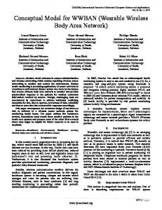
Figure 2.3: Average delay of CGSR+PTS+GCS with multiple radio interfaces provide another possible way to improve the gateways' performance. With multiple radio interfaces, a gateway can access multiple clusters simultaneously by using di�erent codes. Figure 2.3 shows the simulation result of multiple radio interfaces. For the best cost/performance tradeo�, two radio interfaces is the best choice.
2.5 Routing Protocols Routing is a critical component in any multihop wireless network. It is also a key element of multicasting. Thus, particular attention was given to routing in our research. One important requirement in mobile networks is the avoidance of loops which are caused by stale routing tables. Several adaptive, loop free routing schemes have been recently proposed speci cally for wireless, mobile networks [PB94, Gar89]. In our proposed scheme we use as a basis the Destination Sequenced Distance Vector (DSDV) routing scheme [PB94] which was recently
17
12 8
(1)
2
6
(3)
1
15
10
9
(2)
5
13
7
11
14 16
3
4
18 23
21
19
17
22 20 24
(1) (2)
CGSR DSCR
(3) DSDV
Figure 2.4: Routing examples (from node 1 to node 11) implemented in cluster TDMA [GT95] and cluster token [LG95] schemes. DSDV stamps increasing sequence numbers on routing updates relative to a given destination. This way, stale updates can be easily detected and loops avoided. In our project, we modify the DSDV scheme by exploiting the clusterheads. Namely, we use hierarchical routing to route packets. Each node maintains a cluster member table which records the destination clusterhead for each node, and broadcasts it periodically. A node will update its cluster member table when it receives a new one from its neighbor. Here again we use destination sequence numbers as in DSDV to avoid stale tables. There are two tables for each node to route packets. One is the cluster member table which is used to map destination address to the destination clusterhead address, and the other is the routing table which is used to select the next node to reach the destination cluster. We call this cluster (hierarchical) routing scheme DSCR. There are ways to improve the e�ciency of DSCR by optimizing the interaction between routing and MAC layer. The rst strategy we consider consists of routing packets alternatively through clusterheads and gateways. That is, a
18
packet will be routed via C1, G1,C2,G2 ,C3,G3 .., where Ci are clusterheads and Gi are gateways. We call this routing strategy Clusterhead-Gateway Switch Routing (CGSR). Figure 2.4 shows routing examples for DSDV, DSCR, and CGSR. Node 1 is the source and node 11 is the destination. The main di�erence with respect to the previous schemes is that the packet is forced to pass through the clusterhead, avoiding gateway to getaway shortcuts as from node 5 to node 7 in gure 2.4. At rst glance, this may seem to be a drawback rather than an advantage since it increases path length. However, recalling that clusterheads have more chances to transmit than other nodes, and that a gateway-to-gateway transmission requires that both gateways rendezvous on the same code, we realize that the presence of a clusterhead between two gateways is well worth the cost of the extra hop. Experiments verify this conjecture. We can further reduce packet delay by combining CGSR with priority token scheduling (CGSR+PTS), as discussed in section 2. We can go one step further and also add gateway code scheduling (CGSR+PTS+GCS). In the two latter cases, the delay improvement is due to MAC layer features, rather than routing features. In both case, the improvement is obtained by exploiting the knowledge that steady tra�c exists on certain paths in the network, and by assuming that this tra�c will persist in the future. However, in a mobile situation, the paths change continuously, nullifying the advantage of tra�c pattern driven schedules and priorities. To keep the tra�c pattern more stable, we may attempt to reserve the path for a connection (in a virtual circuit fashion) until it becomes disconnected, instead of selecting the new shortest path after each move. Once the rst packet selects the path, all the subsequent packets will follow this path until it breaks. We call this path reservation scheme CGSR+PTS+GCS+PR.
19
0.5
0.7
0.7
0.5
(2)
(0) X’ = X
(1) X’ = X - 1
X’ = X + 1
0.3
0.3
0.5
0.5
(2)
(0) Y’ = Y
(1) Y’ = Y - 1 0.3
Y’ = Y + 1
0.7
0.7
0.3
X : current x coordinate X : current y coordinate
X’ : next x coordinate Y’ : next y coordinate
Figure 2.5: Mobility Model
2.6 MAC and Routing Experiments The MAC and routing strategies described in the previous section have been evaluated via simulation. To this end, a multihop, mobile wireless network simulator was developed using an existing process-oriented, parallel simulation language called Maisie [BL94, CWL97]. This simulator provides an e�cient and exible solution for verifying and measuring multicast protocols. In this section we describe the detailed simulation structure which is used throughout the whole thesis.
2.6.1 Mobility Model Instead of using random mobility model, we explore a probability model which provides a more stable node movement. The probability model is controlled by
20
a three-state Markov chain. Figure 2.5 shows the state-transition diagrams of X-direction and Y-direction. Initially, both X-direction and Y-direction are on state (0). The transition probability matrix P used in our simulator is
P
2 6 6 = 666 4
0 0:5 0:5 0:3 0:7 0 0:3 0 0:7
3 7 7 7 7 7 5
The node move behavior is a�ected by the P and is able to be adjusted by changing P . The node velocity is simulated by triggering the movement every moving period which is speci ed at each run. Each move unit is one pixel which represents one meter. The moving period, for example, of velocity 30 km/hr is 120 ms.
2.6.2 Simulation Parameters The simulation environment consists of 100 mobile hosts roaming uniformly in a 1000x1000 meter square. Each node moves randomly at a preset average speed. Radio transmission range is 120 meter. A free space propagation channel is assumed unless otherwise speci ed. Data rate is 2 Mb/s. Packet length is 10 kb for data, 2 kbit for routing tables and 500 bits for control packets (MAC, polling, etc.). Channel overhead (e.g., code acquisition time, preamble etc) is factored in packet length. Thus, data packet transmission time is 5 ms, 1 ms for routing table, and 0.25 ms for control packet. Routing tables and control messages have higher priority over data. Routing tables are updated every second. This low update rate is consistent with typical wired network operation and is adequate for a static network. As node mobility increases, however, the topology starts changing rather rapidly. In order to maintain accurate routing information, changes in local link status and new routing tables from neighbors trigger new 21
Number of nodes, N Area of movement, A Initial inter-node distance, D Velocity, V Mobility Model Radio transmission range Channel bandwidth Routing table size Data packet size Control packet size Simulation clock
100 1000x1000 meter square Uniform 2 [30m,95m] variable gure 2.5 120 meters 2 Mb/sec 2K bits 10K bits 500 bits 1 tick = 50 �s
Table 2.1: Simulation Topology and Parameters updates. Table 2.1 lists the simulation parameters which are used as default values unless otherwise speci ed.
2.6.3 Performance Evaluation The experiment consists of transmitting a le of 100 packets from one source to one destination (using a free-wheeling protocol such as UDP), and measuring the e�ective throughput (i.e. bits transmitted/total transfer time) for various routing and MAC layer options, with mobility ranging from 0 to 72 km/hr. Figure 2.6 reports the results. It is clear that the combination of cluster (hierarchical) routing, clusterhead/gateway alternation, tra�c pattern driven token scheduling and gateway code scheduling (i.e., CGSR+PTS+GCS) yields a remarkable throughput improvement (typically, between 3 and 4-fold) with respect to the \ at"
22
routing scheme (DSDV), for a broad range of node speeds. Path Reservation, on the other hand, does not appear to improve performance in a consistent manner. Furthermore, path reservation is not easy to implement, since it requires saving the \state" of each connection. For these reasons, in the sequel we use CGSR+PTS+GCS (referred to as CGSR for brevity) as the basic routing algorithm. Figure 2.6 also permits us to assess the throughput degradation caused by mobility. For zero mobility, the CGSR throughput is 450 kbps (i.e., less than one fourth of the maximal channel speed, 2 Mbps). Here, the degradation is attributed to single transmitting/receiving radio multihop, token overhead and code switching overhead. At 72 km/hr, CGSR throughput has dropped to 60 kbps. At high mobility, additional throughput loss is caused by delays and link level retransmissions due to path changes. Average end to end delays were also monitored. The delay results are correlated with throughput results (high throughput ! low delay). In particular, for the CGSR+PTS+GCS case we observed 0.229 s delay for zero mobility. Since the average number of hops was 13 in this case, the average delay per hop is 17.6 ms, which accounts for transmission delay, token latency and code switching. At 20 m/s, the average end to end delay was 2.7 s. The main delay contribution in this case is link retransmission delay. In summary, the results show that the proposed CGSR routing scheme improves the e�ciency of packet delivery and is better applicable to the clusterheadtoken infrastructure which is used as the basic network structure in the following simulations. While the multicast strategies are independent of the particular wireless infrastructure (i.e., routing, MAC and cluster layers) in use, they have been developed on top of a novel wireless, multihop infrastructure for the purpose of evaluating its performance. The underlying infrastructure itself is innovative and
23
Throughput (kbps)
500 450 400 350 300 250 200 150 100 50 0
CGSR+PTS+GCS+PR CGSR+PTS+GCS CGSR+PTS CGSR DSDV
0
10
20
30 40 50 60 Node Mobility (km/hr)
70
80
Figure 2.6: Throughput of CGSR� and DSDV in many aspects improves upon existing architectures. In particular, the LLC clustering algorithm was proven to be more robust to mobility than existing schemes. The clusterhead controlled token MAC layer allows exible priorities and powerful heuristics. The hierarchical routing scheme provides a solution with low overhead and potential for scalability to very large networks.
24
CHAPTER 3 Multicasting with RP Various multicast schemes have been proposed by researchers. Some of the schemes use one or multiple Rendezvous Points (RP ) to maintain multicast structures. In this chapter we explore RP -based multicast schemes and propose an \adaptive" multicast protocol which is able to adapt to the changing environment. Two tree maintenance schemes, namely soft state and hard state, are evaluated via simulations for the RP -rooted multicast trees. RP relocation mechanisms and 2-level mobility models are proposed to improve the performance. Multicast schemes without using any RP s are studied in the next chapter.
3.1 Core Based Tree Multicast The multicast protocol is inspired by the Core Based Tree (CBT) scheme [BFC93]. Each multicast group has a unique multicast identi er (Mid). Each multicast address identi es a host group, the group of hosts that should receive a packet sent to that address. Each multicast group is initialized and maintained by a multicast server (MS) which becomes the core of the CBT for this multicast group. Initially the multicast server broadcasts the Mid and its own node id (MSid) using a ooding algorithm. When a node receives this information, it records the pair Mid and MSid into its multicast database which can be used to join or quit this multicast group. Alternatively to avoid ooding, the multicast
25
server registers the Mid on a directory server. Any node which wants to join a particular multicast group can query the directory server.
3.1.1 Multicast Tree graft and prune The construction and maintenance of the core-based tree is receiver-oriented. When node i wants to join a multicast group G, it rst gets the corresponding Mid and MSid either from its database or from the directory server. Then, it sends a JOIN REQUEST to MSid. The JOIN REQUEST will be routed to MSid (core), using CGSR, until it reaches any node j which is already a member of the host group of G. Node j terminates the JOIN process by sending a JOIN ACK back to node i. A node joins the multicast group and grafts a branch to the multicast tree (core-based tree) upon being traversed by JOIN ACK. Since CGSR routing is used, the internal nodes of the multicast tree are all clusterheads and gateways. Regular nodes can be found only at the leaves of the tree. When internal node n (a clusterhead or gateway) is traversed by JOIN ACK, it records the upstream and downstream node of JOIN ACK. This information will be used to reconstruct the tree when the links in the tree break due to mobility or crash. The clusterhead of node i will record node i as a member of G after it forwards JOIN ACK to node i. When a leaf node wants to quit the group G, it sends a QUIT REQUEST to its clusterhead. The clusterhead will update its membership information and then acknowledge this request with a QUIT ACK. A leaf clusterhead leaves G and sends a QUIT REQUEST to its upstream member when all of its downstream members have quit G. A non-leaf node cannot quit until it becomes a leaf. The above scheme is somewhat di�erent from the CBT scheme proposed in [BFC93], where JOIN ACK must follow the same path as JOIN REQUEST. 26
throughput-duplicate
7800 7600 7400 7200 7000 6800 6600 6400 6200 6000 5800 0.1
ACK tree REQ tree
1 Mobility (km/hr)
10
Figure 3.1: Performance comparison of ACK tree and REQ tree We allow JOIN ACK to follow a di�erent path (from JOIN REQUEST), if so provided by routing tables; and use JOIN ACK to graft links into the tree. The JOIN ACK strategy is more adaptive to a higher mobile situation where routes may change between REQ and ACK. In this case, we want to choose the most current route. Figure 3.1 compares the performance of the two schemes. The tree created by ACK messages achieves higher throughput performance (throughput is the number of packets received by members) under high mobility. The improvement is relatively small, however, since the mobility is not high enough to cause signi cant route changes during the REQ-ACK round trip.
3.1.2 Multicast Tree recon guration The core-based tree is not static since the core and the host group may move. The multicast tree will be recon gured in the following cases: (1) The member of a host group moves and changes node type. (2) Tree links break and transient
27
loops are created.
3.1.2.1 Member migration It is necessary to recon gure the multicast tree when its group members move or change node-type. A group member can detect the change of its multicast tree by monitoring its connectivity to upstream and downstream members. A member node reconnects to the tree by sending a JOIN REQUEST to its multicast server (core) when its upstream member moves out of range or changes node type. For example a clusterhead member will send a JOIN REQUEST to the MSid in order to reconstruct the tree, if its upstream member (a gateway) changes to a regular node, or becomes disconnected. When a regular node member (a leaf) moves out of a cluster Ci and enters into a cluster Cj , the clusterhead of Ci will drop it from its descendant list. The regular node will send a JOIN REQUEST to its new clusterhead of Cj . The clusterhead of Ci will send a QUIT REQUEST to its upstream member if it has become itself a leaf.
3.1.2.2 Loops When a node i wants to join a multicast tree G, it sends a JOIN REQUEST to the core. The JOIN REQUEST will be acknowledged by the rst member in G, which sends back a JOIN ACK to node i. If node i has moved in the interim, the JOIN ACK may trace a di�erent path than the JOIN REQUEST. Thus a loop may be formed. Figure 3.2 shows an example of loop caused by the move of node i. Node i, before the move, sends the JOIN REQUEST to the core on the path a, b, and c. Node c, the rst member in G on the path to the core, returns the JOIN ACK to node i. However, since node i has moved, the new path m, k, o, and p is traced, thus forming the loop c, d, e, f , g, h, k, 28
core g
f
e
h
d k
m
c
Multicast tree o
b
p
a
JOIN_REQUEST JOIN_ACK
i i
i move
Figure 3.2: Loop example and m. To avoid loops, it is required that an established group member, upon receiving a JOIN ACK, return a QUIT REQUEST to the node which sent this JOIN ACK while forwarding the JOIN ACK on the new path. In gure 3.2, for example, node k will send a QUIT REQUEST to node m after it receives a JOIN ACK. At the same time node k will forward JOIN ACK to node o on the new path creating a loop-free branch to node i. We can generalize this loop avoidance method as follows: a group member already connected to the multicast tree will acknowledge a JOIN ACK with a QUIT REQUEST, if this JOIN ACK does not come from its upstream member. Since each group member in a tree can only have one upstream member, a necessary and su�cient condition for loop avoidance is to allow only one upstream member.
3.1.3 Simulation & Performance Evaluation We have implemented the multicast protocol in our wireless simulator in order to evaluate its performance in terms of : (a) control packet overhead; (b) robustness to mobility; (c) scaling properties with respect to multicast group membership, and; (d) response time (i.e., JOIN latency). The environment consists of 100 mobile hosts roaming in a 1000x1000 meter square (as described in section 2.6). 29
The wireless network operates using the LCC clustering algorithm and the cluster token access protocol. As for routing, CGSR is used, unless otherwise speci ed. group members core
Figure 3.3: Initial multicast tree Figure 3.3 shows the initial multicast tree layout, with 7 members plus core. The core is hand-picked. Based on CGSR and clustering properties, the core is a clusterhead and never gives up this role. That is, the core will not change to a non-clusterhead node. Unless otherwise speci ed, we assume that membership is xed. As members move, they leave one branch of the multicast tree and join 30
# of packets; # of reconfig.
2500 ACK pkts JOIN pkts reconfig. events quit pkts
2000 1500 1000 500 0 0
5
10 15 20 Node Mobility (km/hr)
25
30
Figure 3.4: Recon g. & control pkts vs group size another. Furthermore, as nodes move, the routes change, thus causing a dynamic recon guration of the tree topology. It is thus important to measure the control packet overhead caused by these recon gurations as a function of node speed. In these experiments, the main focus is on algorithm response time and control packet overhead. Thus, the network does not carry any user tra�c (only control tra�c) to avoid interference between user packets and control packets. Figure 3.4 shows total number of tree recon gurations during the experiment lifetime as a function of node speed (up to 30 km/hr). We note that the number of recon gurations (i.e., changes in the tree) grows about linearly with speed. In gure 3.4 we also report the number of JOIN, ACK and QUIT packets. While the rst two grow almost linearly with speed, the third is not very speed sensitive. Also, the QUIT event is much less frequent than JOIN/ACK. The reason is that QUIT is issued by a clusterhead or a gateway only when it has no members below it. Figure 3.5 shows the number of temporary loops detected and removed. This 31
# of transient loop
20
15
10
5
0 0
5
10 15 20 Node Mobility (km/hr)
25
30
Figure 3.5: Total # of transient loops number grows with speed, but in an erratic fashion due to the very small sample size. In any event, loop detection and recovery does not cause signi cant overhead. Figure 3.6 reports the recon guration and control packet measurements as a function of membership size. Node speed is assumed xed at 18 km/hr. Control tra�c grows with membership size, as expected, but less than linearly, since the tree route recon guration is independent of membership size. Furthermore, the number of JOIN/ACK packets generated when a member moves from one cluster to another decreases when size increases since there are more members in the tree and the JOIN packet must traverse fewer hops up the tree. On the other hand, the number of moves from one cluster to another increases linearly with the number of members. In balance, we have slightly increasing control packet (ACK/JOIN) tra�c for membership ranging from 7 to 80. The number of QUIT packets decreases with membership size, since, when almost all nodes participate in the multicast, no clusterhead or gateway will ever become childless and thus be forced to quit. In summary, the control packet overhead required to maintain
32
# of packets; # of reconfig.
3000 ACK pkts JOIN pkts reconfig. events quit pkts
2500 2000 1500 1000 500 0 0
10
20
30 40 50 60 Group member size
70
80
90
Figure 3.6: Recon g. & control pkts vs group size the multicast tree does not increase signi cantly with member group size. Figure 3.7 shows packets O/H growth with node speed. Packet overhead is computed using the formula (T � NP )=(ST � NC ), where NP = number of control packet transmission (ACK, JOIN, QUIT); T = control packet transmission time (5ms); NC = average number of clusters (' 27), and; ST = total simulated time (62:5s for our experiments). Thus, the overhead represents the fraction of bandwidth used up by control packets. We note that the growth is less than linear, consistent with gure 3.4 results. Furthermore, the overhead is only a few percent, even at top speed. The responsiveness of a multicast scheme with dynamic join can be measured by the latency of a JOIN operation, i.e. the time between the issue of a JOIN request by a new member and the receipt of an ACK. Intuition suggests that latency should increase with speed. The results in gure 3.8, however, seem to indicate that latency is rather insensitive to speed, at least for the range of speeds considered in our study. For example, using the CGSR routing scheme, JOIN 33
Control packets overhead (%)
3 2.5 2 1.5 1 0.5 0 0
5
10 15 20 Node Mobility (km/hr)
25
30
Figure 3.7: Control packet O/H latency is less than 600 ms for the entire range of speeds. Figure 3.8 also reports latency under the conventional DSDV routing scheme. It is interesting to notice that CGSR performs considerably better than DSDV. The latency reduction in CGSR can be attributed to the clever token and code scheduling heuristics. In summary, the result show that the proposed multicast scheme meets the target performance goals. Namely, it is robust to mobility (latency is insensitive to speed; overhead increases less than linearly with speed); it has low overhead (less than a few percent at top speed); it scales well with member group size, and; it has very low latency (less than 1 s).
3.2 Hard State versus Soft State Tree Maintenance In shared tree multicast protocols, the tree maintenance protocol must keep track of downstream and upstream links at each node, for each multicast group. When a node in the tree receives the multicast packet, it will forward it only to down-
34
Average latency of JOIN (ms)
1100 DSDV CGSR
1000 900 800 700 600 500 400 0
5
10 15 20 Node Mobility (km/hr)
25
30
Figure 3.8: Average JOIN latency stream links, if any (except, of course, the link the packet came from). Thus each intermediate node must keep the state of its downstream members. E�cient updating of link states has a critical impact on the performance of multicasting. For graft-based multicast [BFC93], nodes wishing to join the group send a JOIN REQUEST message to the RP. All nodes traversed by the JOIN REQUEST will save the join state to maintain the downstream links. There are two major schemes to maintain the shared tree. One is \hard state", and the other is \soft state".
3.2.1 Hard State Protocol In the hard state protocols, when a node wants to join a multicast group, it must send an explicit JOIN REQUEST and wait until it is acknowledged to become a member. A member will keep its membership until it intends to quit or the connection is broken. Namely, the upstream node in the multicast tree keeps a link in "downstream" state until it receives an explicit QUIT REQUEST from 35
the downstream node or when the downstream link is disconnected. The hard state protocol relies on the underlying MAC protocol to provide the link connectivity information. Only if the MAC layer provides reliable, periodic link state information, can the hard state protocol adjust to connectivity change (i.e., it can e�ciently prune broken links and establish new connections to the tree). For example, in the mobile wireless networks, when a downstream member of node i moves out of the transmission range of node i, it will send a new JOIN REQUEST to setup a new link to the tree. The original downstream link is disconnected. Since hierarchical routing is used, the internal nodes of the multicast tree are all clusterhead or gateway types. A regular node type (i.e., neither gateway or clusterhead) can be found only at the leaves of the tree. In this cluster infrastructure, the multicast tree structure in hard state will be recon gured only in the following cases: (1) The member of a host group moves and changes node type. (2) Tree links break (potentially creating loops).
3.2.1.1 Member migration It is necessary to recon gure the multicast tree any time a group member moves or changes node-type. A group member can detect changes in the multicast tree by monitoring its connectivity to upstream and downstream members (as mentioned before, this must be done by MAC layer). A member node reconnects to the tree by sending a JOIN REQUEST to the RP when its upstream path becomes disconnected (e.g., the upstream node moves out of range or changes node type from clusterhead/gateway to regular node). For example, a clusterhead member will send a JOIN REQUEST to the RP in order to reconstruct the tree, if its upstream member (a gateway) becomes a regular node, or becomes disconnected. When a regular node member (a leaf) moves from cluster Ci to cluster Cj , the
36
clusterhead of Ci will drop it from its descendant list. The regular node will send a JOIN REQUEST to its new clusterhead in Cj . The clusterhead of Ci will send a QUIT REQUEST to its upstream node if it has itself become a leaf.
3.2.1.2 Multicast Tree Recovery In the multicast tree, an internal node has one parent and one or more children. If the parent link is disconnected, the internal node can recover either by resending JOIN REQUEST message to connect to the tree via a new parent, or by sending FLUSH TREE message to its children. The FLUSH TREE message propagates to the entire subtree, forcing all downstream leaf-members to rejoin the tree individually. A rejoin by the internal node will be quicker than by leafmembers, but it may occasionally create a temporary loop (rejoin to its own downstream node). In a mobile environment, we prefer to use the ush scheme to avoid temporary loops.
3.2.2 Soft State Protocol In the soft state protocol, a node which wants to remain in a multicast group must periodically send a JOIN REQUEST to the RP. No ACK is required. The node receiving a JOIN REQUEST from its neighbor will store a state for this neighbor as a downstream member and will attach a time stamp to it. The upstream node will update the state timer when it receives another join request (state-driven refresh). The downstream node is automatically expelled from membership when its timer expires. There is no need to keep track of the upstream node. Every node receiving the JOIN REQUEST just forwards it to the RP using the underlying routing scheme. This is di�erent from Hard State, where the state of the upstream node must also be kept. Soft state provides a fail-safe method for a dynamically 37
changing environment and relaxes the link connectivity dependency on MAC layer. Note that reliable link connectivity maintained at the MAC layer is also required for cluster and route maintenance. However, there are nodes (e.g., low power or high mobility) which would never be used as clusterheads or gateways in the hierarchical routing scheme. Thus, the connectivity of these nodes will be updated only sporadically (to save power for example). The sporadic MAC layer connectivity maintenance of low power nodes, say, causes potential problems for Hard State, but, is compensated by the periodic refresh in Soft State. The time periods for refresh (Trefresh) and timeout (Ttimeout ) must be carefully chosen taking into account mobility and channel access overhead. In a highly mobile network, a short refresh period is desirable, but it will increase the channel overhead. If the timeout period is long, there will be stale links and wasted duplicate transmissions on such links. If the timeout period is short, branches are prematurely cut o� and data may be lost. In order to achieve low overhead and yet maintain connectivity, it is very important to judiciously (possibly, dynamically) select the time period for refresh and timeout. These tradeo�s are explored in the experiments described in the following sections.
3.2.3 Simulation & Performance Evaluation Simulation environments described in section 2.6 are used to evaluate the performance of hard state and soft state schemes. The RP is hand-picked and does not change throughout the experiment. Dynamic relocation of the RP could improve the e�ciency of the tree algorithm. This option, however, is not considered in our study since it would not a�ect the Hard State vs. Soft State tradeo�s. Members are randomly selected to join and quit the multicast group. On average,
38
seven members are part of the group. Figure 3.3 shows a typical multicast tree con guration. There is a single source of multicast tra�c, placed at the RP. Tra�c input rate is high enough to fully load the network. Nodes have a nite bu�er. Packets are dropped when bu�ers over ow, or when there is no route to the intended destination, because the topology is disconnected or the routing tables have not yet been updated. For the sake of simplicity we also assume that nodes (and in particular gateways) can receive on multiple codes simultaneously (e.g., using multiple receivers). This property does not enhance communications within a cluster, since all wireless nodes are tuned to the same code anyway. It does, however, permit con ict free communications with the gateways, and in particular con ict free multicast from clusterhead to gateways. Without the multiple code reception, the gateway must tune on di�erent codes (of the adjacent clusters) and can receive correctly only if it is tuned to the transmitting clusterhead code. For example, in [LG97] we assume that each gateway takes turns in tuning to the codes of the adjacent clusters for a fraction of time dependent on the tra�c pattern. For the purpose of this study, however, the overhead penalty of any of the above remedies will a�ect equally the multicast schemes we are comparing without changing the ranking. Thus, for simplicity, we have opted for the multiple code reception. Total simulation time for each experiment is 2x10⁶ simulation ticks. One simulation tick corresponds to 10 �s. Thus, each run represents 20 seconds of simulated time. In this section, we rst evaluate the soft state scheme and select the values Trefresh and Ttimeout which optimize its performance (for the given systems parameters). Then, using these values, we compare the performance of hard state and soft state using as criteria throughput, join latency, and control overhead.
39
3.5 mobility 72.00 km/hr mobility 36.00 km/hr mobility 18.00 km/hr mobility 7.20 km/hr mobility 3.60 km/hr mobility 1.80 km/hr mobility 0.90 km/hr mobility 0.45 km/hr
6 3
2.5 duplicate (Mbps)
throughput (Mbps)
5
4
3 mobility 0.45 km/hr mobility 0.90 km/hr mobility 1.80 km/hr mobility 3.60 km/hr mobility 7.20 km/hr mobility 18.00 km/hr mobility 36.00 km/hr mobility 72.00 km/hr
2
1 1
2
1.5
1
0.5
0 10 T_refresh (ms)
100
1
10 T_refresh (ms)
100
Figure 3.9: Soft State: impact of Trefresh and mobility
3.2.3.1 Soft State Parameter Optimization The performance of the soft state scheme depends critically on the selection of refresh and timeout intervals. We will evaluate the e�ect of Trefresh and Ttimeout for various parameter settings. To this end, we rst de ne total throughput performance as the total tra�c received by members. Some of the received packets however may be duplicates, as described in section 3.2.2. Thus, we de ne throughput as (total received packets) - (duplicate tra�c).
Mobility vs. Trefresh : First we study the relationship between Trefresh and mobility. Recognizing that for stability the timeout must be larger than the refresh period, we set Ttimeout = 10 � Trefresh. We then evaluate throughput and duplicates for various values of Trefresh and mobility. From gure 3.9 we note that high mobility causes more duplicates and lower throughput. To improve higher throughput at high mobility, Trefresh must be reduced so as to adapt to the rapidly changing topology. However, as Trefresh is reduced, Ttimeout is also becoming smaller, eventually causing throughput degradation due to frequent timeout and tree disconnects. When Trefresh is large, Ttimeout tends to become too
40
3 2.5
6.2
duplicates (Mbps)
throughput (Mbps)
6.4
6 5.8 5.6 5.4
2 1.5 1 0.5
5.2 5
0 2
4
6
8
10
12
14
16
2
4
6
8
N
10
12
14
16
700
800
N
Figure 3.10: Ttimeout = N * Trefresh @ mobility = 0.45 km/hr 3 2.5
6.2
duplicates (Mbps)
throughput(Mbps)
6.4
6 5.8 5.6 5.4
2 1.5 1 0.5
5.2 5
0 0
100
200
300
400 500 T_refresh
600
700
800
0
100
200
300
400 500 T_refresh
600
Figure 3.11: Trefresh @ mobility = 0.45 km/hr long, thus increasing the duplicate overhead. The system is particular sensitive to Trefresh at high speed.
Trefresh vs. Ttimeout : Next, we vary Trefresh and Ttimeout simultaneously to nd the best combination. Starting with low mobility, gure 3.10 shows throughput and duplicates with mobility = 0.45 km/hr and Trefresh= 400 ms. The throughput is not a�ected by large timeout since the topology does not change too rapidly and thus few duplicates are created anyway. In gure 3.11 we x the timeout interval to 1600 ms and vary Trefresh. Again, we note that throughput and duplicates are not very sensitive to refresh interval. Next we study the high mobility case (72 km/hr). Now, throughput and duplicates are much more sensitive to Trefresh and Ttimeout (see gure 3.12 and 3.13). 41
3
3.5
2.5 duplicates (Mbps)
throughput (Mbps)
4
3 2.5 2 1.5
2 1.5 1 0.5
1 0.5
0 0
5
10
15 N
20
25
30
0
5
10
15 N
20
25
30
3
3
2.8
2.5 duplicates (Mbps)
throughput(Mbps)
Figure 3.12: Ttimeout = N * Trefresh @ mobility = 72 km/hr
2.6 2.4 2.2
2 1.5 1 0.5
2
0 0
50
100
150 200 250 T_refresh
300
350
400
0
50
100
150 200 250 T_refresh
300
350
400
Figure 3.13: Trefresh @ mobility = 72 km/hr From the above results it is clear that both Trefresh and Ttimeout must be modi ed as mobility varies, in order to optimize throughput. Table 3.2.3.1 presents the optimal results for various mobility values obtained via repeated simulations. We note that the optimal value of Trefresh is inversely proportional to speed. For example, a 100 fold reduction of speed (from 72 km/hr to 0.9 km/hr) requires an increase of Trefresh from 25 ms to 2000 ms. This was expected since the higher the speed, the lower the refresh period to track the changes in topology. The timeout also must decrease as speed increases. However, it should not decrease so rapidly as Trefresh, in order to avoid unnecessary tree disconnects. We use the parameters in table 3.2.3.1 for soft state scheme to compare the performance evaluation with hard state.
42
Mobility (km/hr) Trefresh(ms) Ttimeout 72 25 250 36 50 300 18 100 450 7.2 250 600 3.6 500 850 1.8 1000 1100 0.9 2000 2100 0.45 4000 4100 Table 3.1: parameters of higher throughput
3.2.3.2 Join Latency Next, we evaluate the join latency, namely, the time required for a new member to join. For soft state, there is no explicit JOIN ACK like in the hard state protocol. Thus, we measure the join latency as the delay time between the rst JOIN REQUEST and the rst multicast data arrival. For hard state, we de ne two measures for join latency, namely: ACK delay (time between JOIN REQUEST and JOIN ACK) and data delay (time between JOIN REQUEST and rst multicast data arrival). Figure 3.14 shows the average join latency for various mobility values. As expected, the join latency of soft state is lower than the data delay of hard state. This is because the hard state protocol requires the issue of JOIN ACK before data is sent. Conversely, soft state join latency is higher than hard state ACK delay because the ACK packet is much shorter than the data packet.
43
average initial join delay (ms)
100 80 60 40 hard state:data soft state hard state:ack
20 0 1
10 Mobility (km/hr)
Figure 3.14: Join Latency
3.2.3.3 Control Packet Overhead In hard state, the control messages required to maintain the multicast tree are: JOIN REQUEST, JOIN ACK, QUIT, and CLEAR messages. For soft state protocol, only JOIN REQUEST is required. Figure 3.15(a) shows the individual control tra�c components of hard state, and gure 3.15(b) compares the total control tra�c of hard state and soft state. The control tra�c of hard state increases with node mobility, because higher mobility causes more tree disconnects and therefore triggers more join requests. For soft state, control tra�c is independent of mobility as long as Trefresh is a constant. The explicit control messages in hard state are much fewer than in soft state, but the hard state protocol requires the underlying MAC layer protocol to continuously probe link connectivity.
44
1400
100000
# of control messages
1000
# of control messages
join ack join request clear quit
1200
800 600 400
10000
1000
100
200 0
10 1
10 Mobility (km/hr)
1
soft state:T_refresh = 10ms soft state:T_refresh = 200ms hard state soft state:T_refresh = 3200ms 10 Mobility (m/s)
(a) Hard State (b) Total Control Messages Figure 3.15: Control Messages
3.2.3.4 Throughput Comparison Figure 3.16 compares the throughput of hard state and soft state. The soft state experiment uses the best choice of refresh and timeout timers found in our simulations. Soft state performs better than hard state at high mobility This is mainly due to two reasons: (a) in soft state, the join delay is lower than in hard state, thus, fewer packets are dropped during disconnect. (b) when the tree becomes disconnected, hard state su�ers the additional delay of ushing the subtree, before the members have the chance to create a new subtree.
3.3 RP Tree Multicast Strategies Tree multicast is a well established concept in wired networks. Two versions, per-source tree multicast (e.g., DVMRP) and shared tree multicast (e.g., Core Based Tree), account for the majority of the wireline implementations. In this paper, we extend the tree multicast concept to wireless, mobile, multihop networks for applications ranging from ad hoc networking to disaster recovery and battle eld. The main challenge in wireless, mobile networks is the rapidly changing environment. We address this issue in our design by: (a) using \soft state";
45
6.5
throughput (Mbps)
6 5.5 5 4.5 4
soft state hard state
3.5 3 2.5 2 1
10 Mobility (km/hr)
Figure 3.16: Throughput (b) assigning di�erent roles to nodes depending on their mobility (2-level mobility model); (c) proposing an adaptive scheme which combines shared tree and persource tree bene ts, and; (d) dynamically relocating the shared tree Rendezvous Point (RP ). A detailed wireless simulation model is used to evaluate various multicast schemes. The results show that per-source trees perform better in heavy loads because of the more e�cient tra�c distribution; while shared trees are more robust to mobility and are more scalable to large network sizes. The adaptive tree multicast scheme, a hybrid between shared tree and per-source tree, combines the advantages of both and performs consistently well across all load and mobility scenarios. The multicast service is critical in ad hoc network scenarios characterized by the close collaboration of teams (e.g., rescue patrol, battalion, scientists, etc.) because of the audio/video conferencing requirements and the sharing of text and images. Multicasting in a mobile, multihop wireless network is much more 46
complex than in wired networks because of node mobility, broadcast radio channel and hidden terminal e�ects. There are many di�erent ways to attack this problem. In this paper we approach the problem by transferring and adapting to the wireless environment the multicast solutions used in wireline networks such as the Internet. We modify and extend these solutions to account for mobility, dynamically changing topology and radio channel characteristics. To set the stage, we review in the sequel two popular wired network multicast schemes, namely, per-source shortest tree and shared tree. We identify their limitations when applied to a wireless, mobile environment, and preview possible solutions. The per-source tree scheme consists of broadcasting the packet from the source to all destinations along the source tree using \reverse path forwarding". An arbitrary network node will accept the packet broadcast by source S as long as the packet is received from the shortest path emanating from S. This provision is required in order to avoid endless looping. Examples of per-source tree are DVMRP [DC90] and PIM dense mode [DEF97]. Per-source tree multicasting has many attractive properties. To begin, the shortest tree from each source to all destinations generally comes for free since it is embedded in the routing tables of the most common routing algorithms such as Distance Vector and Link State. Furthermore, source tree multicast distributes the tra�c evenly in the network (assuming that sources and receivers are evenly distributed); it requires minimal initialization and maintenance; and it does not rely on a central control point (e.g., rendezvous point). In mobile networks, however, the per-source tree approach presents a problem. Suppose a source moves faster than the routing tables can track it. In this case, some of the nodes have obsolete routing tables which point in the \wrong direction". Following the \reverse path forwarding" principle, multicast packets are dropped at such nodes and may never reach some of the receivers. 47
Another popular wired network scheme is shared-tree multicast. In this scheme, a single tree rooted at a Rendezvous Point (RP ) is maintained (instead of many per-source trees). Examples of shared-tree approach are CBT [BFC93, CZ95] and PIM sparse mode [DEF96]. The shared tree is less sensitive to source mobility and can in part overcome the above mentioned fast moving source problem. Namely, a very fast source will send its packet to the RP in unicast mode. Packets are correctly delivered to the RP on shortest paths, irrespective of the speed of the source. The RP will then multicast the packet on the shared tree to the intended destinations. This works as long as the shared tree is stable. If ALL the nodes are moving fast (relative to routing table updates), the shared tree solution also fails. In many practical applications however it turns out that only a fraction of the nodes is fast moving, while the remaining nodes are static or relatively slow moving. This 2-level mobility model, further elaborated in section 3.3.5.1, allows us to de ne a stable routing scheme and therefore a shared tree which is robust to mobility. The shared tree approach has some drawbacks of its own with respect to the per-source scheme. First, paths are non optimal and tra�c is concentrated on the backbone tree, rather than evenly distributed across the network. This leads to lower throughput e�ciency. To reduce path costs and distribute tra�c more evenly in the network we allow a receiver to request, under certain conditions, that a source deliver the multicast messages to it on the shortest path rather than on the shared tree path. This feature, inspired by the PIM protocol [DEF96] and referred to as \adaptive tree multicast", is described in section 3.3.2. Secondly, as the entire network moves and the membership changes dynamically, the RP may be \o� center", thus further aggravating the non optimality of the paths. To overcome this problem, a dynamic relocation strategy is proposed in section 3.3.4.
48
Related research on multicasting for ad hoc wireless networks has been reported in [CB95]. In particular, the Reservation Based Multicast scheme [CB95] also uses the notion of Rendezvous Point and the concept of combining distributed routes and shared tree. However, the main emphasis there is on resource reservation and allocation in a large wireless network rather than on throughput ef ciency in the presence of mobility. The interaction of network protocols with lower layer protocols and the e�ect of control tra�c have not been modeled in detail.
3.3.1 Shared Tree Multicast As previously discussed, the shared tree scheme is of interest in wireless, mobile networks for its potential of low overhead and adequate stability even in the presence of fast moving sources. The shared tree scheme supports many-to-many casting, with several senders and receivers. In each multicast group, packets sent by sender members will be delivered to all receiver members. The shared tree approach is based on the notion of a rendezvous point (RP ) [DEF96, CB95]. Sender members send multicast packets towards the RP , and receiver members send join requests to RP . Multicast packets will be forwarded to receiver members along the multicast forwarding tree. The RP-rooted tree is created by receiver members which periodically send join requests to RP . The join request contains the forward list which is initially set to \all senders f�g". This makes the scheme very scalable to large number of senders. All internal nodes traversed by the join request are enpowered to forward the multicast packets (from RP ) to the receivers as speci ed by the forward list instructions. Active members periodically refresh the forwarding list. We use a soft state approach in which branches are deleted if not refreshed within a
49
join requests (from R to RP)
R2 RP
join requests (from R to RP)
R2 RP
multicast data
multicast data
encapsulated unicast date
Nj
Nj fs1
f* R1
f* S1
R1
Figure 3.17: Example of unicast sender mode
S1
Figure 3.18: Example of multicast sender mode
timeout. An alternate approach is to maintain "hard state" forwarding lists and to require explicit leave requests in case members leave or relocate. A previous study has shown that the soft state tree maintenance scheme performs better than the hard state one for a mobile environment in which the shared tree must be continuously recon gured [CG97]. Within the general shared tree protocol framework, there are several variants which can be implemented. In this paper, we examine and compare two di�erent schemes as discussed below.
Unicast sender mode: A sender does not know (nor does it need to know)
all the receiver addresses. It only knows the RP address and the multicast address. The simplest way for it to send a packet to the group is encapsulating it and unicasting it to RP . Then, RP will forward the packet to all receive members. The internal nodes along the path to the RP cannot intercept the packet and forward it in multicast mode since the multicast address is hidden, i.e., encapsulated within the unicast address to RP . Figure 3.17 shows the shared tree maintained by the join requests. Packets sent by sender S 1 will be unicast to RP (unicast sender mode) and then forwarded to receivers R1 and R2. The
50
detailed protocol for unicast sender mode is shown in appendix A.1.
Multicast sender mode: Bandwidth e�ciency is improved if the packet can be forwarded directly to the members on the tree without looping back through the RP . If the packets are not encapsulated (i.e., use multicast address), the internal node Nj in gure 3.17 can forward the packets directly to R1. To enable the "multicast" sender mode, the RP after receiving the rst packet from sender Sk , automatically registers Sk and periodically sends a join message to Sk (soft state). As a results, all nodes traversed by the join message will now include Sk in the multicast address list. Thus, they will be able to forward packets from Sk in multicast mode. After receiving the join message, Sk broadcasts unencapsulated multicast packets. Figure 3.18 illustrates the multicast sender mode. Appendix A.2 describes the detailed protocol. In general, multicast sender mode improves performance, as shown in section 3.3.5.3 results. Note however that as source Sk moves, the RP must continuously refresh the path to Sk with join requests. If Sk moves too fast for RP to keep track of it, some of the receivers will miss the packets. To overcome this problem, a \fast source" feature as discussed in section 3.3.5.1 forces a fast source to use unicast sender mode. Another limitation of this scheme is scalability, since intermediate nodes now must keep track of senders.
3.3.2 Adaptive Tree Multicast The multicast sender mode previously described allows senders to broadcast packets directly using the multicast group address instead of encapsulating them in a unicast address. This is a major improvement with respect to unicast addressing. There is still a potential ine�ciency, however. There may be packets traveling from source sk to receiver rj on paths which are much longer than the
51
shortest path between sk and rj . It would be desirable for a receive member to receive packets directly from a sender without being forced to travel on the RP tree, especially if the sender is nearby [DEF96]. Another important incentive to switchover to the per-source tree is to reduce the load at the root of the shared tree. More generally, it would be desirable to switch between RP-rooted shared tree and per-source tree dynamically on a receiver/sender pair basis, using relative path-length/link-load tradeo�s as criteria. Selective per-source multicasting improves throughput and reduces delay and multicast cost (in terms of total link transmissions), the latter depending on the amount of sharing on RP tree vs. per-source tree. In the proposed adaptive tree multicast scheme, receiver rj can elect to receive packets sent by sender sk either from the RP-rooted shared tree or from the persource tree based on path length comparison. Note that the path from sk to rj on the RP rooted tree is shared among many receivers. Thus, the incremental savings may be lower than the cost of establishing and using a separate shortest path. Likewise, RP bottleneck load is relieved only if there is a decrease in the number of RP neighbors charged with forwarding sk packets. If the set of receivers is dense, this may require several receivers to switchover to the persource tree simultaneously. Clearly, it is di�cult to capture all of these tradeo�s in a single link metric and path length comparison. With simplicity in mind, we propose the following heuristic. First, the receiver checks if the hop count carried in the header of the packet from sk is larger (by a given margin) than the distance (as per routing table) from rj to sk . Then, it checks if the distance from rj to sk is shorter (by another margin) than the distance from rj to RP . This check gives an approximate measure of the link cost savings after switchover: if the distance to sk is much
52
RP
RP Sk
Rj
Sk
Rj
(a) switch (b) no switch Figure 3.19: Examples of adaptive tree multicast larger than the distance to RP , there is little incentive in creating a new, largely non shared path. If both checks are satis ed (within margins which are adjusted for the speci c application), rj can switch from the RP rooted tree to sk -rooted tree (per-source tree). To accomplish this, the receiver issues a join request with forwarding list FLj = fsk g to sk to establish a forward path from sk to rj , and suppresses sk in the join requests to RP , i.e., FLj = f� ? sk g. Soft state eliminates stale branches in the shared tree (timeout timer). After timeout, the forwarding of packets from sk on the RP rooted tree to rj will cease. If nodes move and path lengths change, rj may switch back to the RP rooted tree. To do this, rj stops sending join requests to sk and adds sk in the join requests to RP . By measuring path length, receiver members can adaptively switch between RP rooted tree and per-source tree. Note that the Adaptive Tree Scheme requires intermediate nodes to keep track of the sources elected for per-source tree delivery. This impacts the scalability to large number of sources. Figure 3.19 illustrates the switchover process. Let P = hop count and D = distance (assume the margin to be zero). In gure 3.19(a) Pj;k > Dj;k and Dj;k < Dj;RP . Rj will switch from RP rooted tree to per-source tree for receiving data from Sk . In gure 3.19(b), Pj;k > Dj;k but Dj;k > Dj;RP . Rj will not switch since receiving from RP is more e�cient and avoids an increase in control overhead. 53
fS2
R2 f*
f*-S1
join messages (from RP to S)
f*
RP
join messages (from RP to S)
f*-S2
multicast data
multicast data
S2
fS1 f*
f*
f*
fS2
R4
R4 R1
join requests (from R to RP & S)
RP
S2 f*
R2
R3
join requests (from R to RP)
R3
R1
S1
S1 fS1
(a) multicast sender mode (b) Per-Source Trees Figure 3.20: Examples of per-source tree multicast Appendix A.3 shows the detailed protocol for adaptive tree multicasting.
3.3.3 Per-Source Tree Multicast To evaluate the performance of adaptive tree multicast, a per-source tree mechanism is formed by always switching over to per-source mode in the switchover process of adaptive tree scheme. Namely, when receiver rj receives packets sent by sk from the RP -rooted shared tree, it issues a join request to sk to establish the path from sk to rj and suppresses the tra�c of sk from RP by removing sk from the forwarding list FLj in the join request to RP . There is no switch back to RP in all situations. Figure 3.20 shows an example of per-source trees after switcher. Note that although all receivers switchover to per-source mode, senders still need to send packets to RP because the RP needs to maintain the up-todate information of senders in order to serve any new joining members. Without updated information, senders would be removed from RP 's member list after timeout and then new joining members cannot get any packets. This per-source tree scheme, which is assisted by the RP , is di�erent from DVMRP which uses
ooding and prune/graft messages to maintain the per-source trees.
54
3.3.4 RP Dynamic Relocation In the shared tree scheme, a xed RP location can be a problem when the membership changes dynamically. Consider rst a wired, wide area network. In a particular multicast workgroup application, the RP is initially placed in New Jersey since most of the members in the early hours of the morning are on the East Coast. At the end of the day, the members are all on the West Coast, and yet are supported by an RP thousands of miles away! An o� center RP causes two types of ine�ciencies: (a) extra tra�c overhead, since multicast messages are delivered to the RP (and in some cases must loop back around the RP ), and; (b) poor routing (and therefore higher delays) since the messages must travel on a tree rooted at a far o� RP . In wireless, mobile networks, the RP o� center problem is even more likely to occur since user nodes and RP may move. Prior research on RP relocation is reported in [WE95] and in [CZ95], where, the relationship between RP choices and performance is addressed. In [CZ95] the static RP location optimization problem is addressed. Namely, for a broad range of topologies and applications, and under various performance criteria (bandwidth, delay and tra�c concentration) three RP selections strategies are de ned: random, topology based and membership group based. The strategies are compared among each other and to the per-source multicast tree solution. The main conclusion is that from the bandwidth cost point of view the topology based and membership based RP solutions perform as well as (and in some cases surpass) the per-source rooted solution. From the delay point of view, the per-source rooted solution is still superior, as expected. Another important observation is that the performance is rather insensitive to RP speci c location, as long as the RP is reasonably centered. The above studies have addressed a static topology and multicast member55
ship. In our case, both topology and membership change dynamically. As a consequence, we must implement a \dynamic" RP relocation strategy. Two types of strategies can be pursued: (a) centralized, where a network control center constantly monitors the global network status (using for example a Link State type topology monitoring and routing scheme) and periodically evaluates all RP candidates, or; (b) distributed, where each RP candidate independently computes its e�ectiveness as RP and competes with the neighbors for the RP role. In this paper, we follow the second approach, which is more compatible with the distributed nature of wireless multihop architectures and routing schemes. Before introducing the actual distributed RP relocation algorithm, we must de ne the performance measure to be optimized. A key concept in these de nitions is the shortest path tree from the RP to the multicast group members, henceforth referred to as RP shortest tree. Four performance measures can be de ned for this tree [CZ95]: (a) average hop distance from the RP to all members (this measure is minimized by selecting the center of mass); (b) height of the RP shortest tree (i.e., max hop distance from RP to any member, which is proportional to max end to end delay); (c) total number of links in the RP shortest tree, proportional to bandwidth overhead since each multicast message must traverse all the links of the tree; (Note: the number of links varies from tree to tree since the number of internal nodes varies); and (d) tra�c concentration i.e., number of messages per link. Tra�c concentration is proportional to tra�c congestion and therefore queueing delay on each link. Di�erent objective functions will lead generally to di�erent RP locations. In the sequel, we will present optimization schemes for di�erent measures. First, we introduce the algorithm for measures (a) and (b), which are the easiest to implement with typical Routing Table setups. We assume (without
56
loss of generality) that cluster routing is used and that only clusterheads are RP candidates.
RP relocation algorithm 1. Current RP evaluates its own cost. Either (a) or (b) measure can be directly computed from routing tables and from member list. Note: RP knows source and receiver IDs because of periodic refresh. 2. Current RP distributes the current member list to the neighbor clusterheads. 3. Neighbor clusterheads compute their own costs (from their routing tables) and return such costs to the RP . 4. Current RP delegates RP role to lowest cost clusterhead, if such cost is lower than its own. (within a threshold, to avoid oscillations) 5. Newly elected RP refreshes the paths to all sources and triggers a refresh (to itself) from all receivers. This procedure is carried out periodically, in a background mode. Note that this procedure can also be used to recover from RP failure. The \runner up" in the last election can take charge if the current RP has been silent beyond a given timeout. Generally, a downhill procedure like the above will lead to a local minimum. However, for measures (a) and (b) we have shown that for regular topologies (e.g., rectangular grid with cross links, circular grid. with rings and spokes) the function is convex over the discrete set of candidates [GC98]. Thus, a local minimum is also a global minimum. This property is hard to prove for general topologies. However, we have examined the behavior of the above measures 57
for several randomly generated topologies, and have experimentally veri ed that there is only one local minimum, which is also the global minimum (see gures A.2 and A.3 for examples). As for measure (c), i.e., number of links in the RP shortest tree, the problem is a bit more complex since such information cannot be directly extracted from the routing tables (it could, however, be easily computed from the global topology information maintained by a Link State routing algorithm). With a Distance Vector type algorithm, this goal can still be achieved using a \parent tree" data structure which is constructed in a distributed fashion in parallel with the routing vector [HS90, GKA83]. The parent tree representation of a tree is an N dimensional vector (N = number of nodes) where the i-th entry is the parent of node i. Parent tree vectors are exchanged between neighbors at the same time as routing vectors. Using the parent vectors and routing vectors received from the neighbors, each node constructs the parent vector of the shortest tree with itself as the root by merging the parent trees from the neighbors. Each RP candidate can compute the number of links as required in (c) by \walking" up the parent tree from each group member. Details are found in [GC98]. Note that this scheme introduces extra O/H in the network. In fact the routing overhead is practically doubled. The RP relocation algorithm for measure (c) is identical to the one reported above for (a) and (b), except for the new objective function. As for the global optimum property, this is hard to prove even in regular topologies. The reason is that regular topologies (e.g., rectangular grid) o�er many alternate shortest paths between each node pair. To minimize link cost, one must select these paths so that they overlap as much as possible. This is in itself a combinatorial problem. Nevertheless, we were able to show global optimality for the circular
58
grid topology [GC98]. Moreover, we have veri ed global optimality in several randomly generated topologies (see gure A.4 for an example). As for measure (d), tra�c concentration, the \parent tree" data structure proposed for measure(c) can again be used for this computation, by tracing the paths from the sources and counting the ows on each link. Alternatively, the routing tables received from the neighbors can be used to identify the loads incoming from the neighboring clusters. In summary, RP dynamic relocation is feasible and practical in wireless networks. As a side bene t, it provides automatic RP failure recovery. The complexity of the relocation strategy depends on the objective function used. In the following we will evaluate the performance improvement yielded by RP relocation and the cost e�ectiveness of di�erent objective criteria.
3.3.5 Simulation & Performance Evaluation Performance of above schemes has been evaluated via the simulation. We measure the performance of RP -based multicast using unicast sender mode, multicast sender mode, adaptive tree scheme, and per-source trees for di�erent mobility models and tra�c loads. A distributed RP relocation mechanism has been implemented into the simulator to measure its e�ciency.
3.3.5.1 Mobility : Models and Countermeasures To understand the limits of our proposed multicast solutions with respect to mobility, it is important to develop a realistic and yet manageable mobility model. By examining various fast deployable, wireless multihop environments such as ad hoc networking, disaster recovery and battle eld, we observe that while some
59
nodes are moving very fast (e.g., helicopters, aircraft, ambulances, etc.), others are static or relatively slow moving (e.g., command posts, observation vehicles, etc.). This suggests the establishment of a 2-level mobility model: some nodes are stationary or move at speed below routing maintenance threshold, and other nodes move too fast to maintain accurate routes to them and to be relied upon for store and forward routing. Let us assume that the \slow node" population is dense enough to form a connected topology spanning the entire area. Furthermore, fast nodes are in radio contact with one or more slow nodes at all times. In this case, some of the previous protocols can be \customized" so that the impact of mobility is minimized. To this end, we assume that each mobile node can measure its velocity and determine its status (slow or fast). To begin, the 2-level mobility model can be easily matched with the 2-level routing algorithm based on clusters and clusterhead routing as de ned in 3.3.5.1 [GT95]. Clusterheads and gateways are xed or slow moving nodes. The assumption of dense population of slow nodes guarantees the existence of a connected solution. Only clusterheads (and gateways between clusters) support the high level routing and store and forwarding. This provides a fairly stable backbone supported by slow nodes through which peripheral nodes (including fast nodes) can be reached. The mobility model is exploited also in the multicast protocol design. In the shared tree scheme, the fast source uses the \unicast sender" option beyond a certain speed (say, 30 km/hr) to avoid routing table misdirections as mentioned in section 3.3.1. In the adaptive tree scheme, the fast source informs all receivers of its status (by stamping a \fast" bit in the header, for example). The receivers will not switch to the per-source tree if the source is fast.
60
3.3.5.2 Simulation Environment The simulator described in section 2.6 is used and A 2-level mobility model is involved in some of the experiments, where nodes are subdivided in two classes, slow and fast, at network initialization. In the 2-level mobility model, fast nodes move at speed up to 90 km/hr. Slow nodes move at walking speed (1.4 km/hr). Node bu�er size is 10 packets. Multicast members are randomly selected to join and quit the multicast group. In heavy load experiments, tra�c input rate is high enough to fully load the network. Total simulation time for each experiment is 4x10⁶ simulation ticks. One simulation tick corresponds to 50 �s. Thus, each run represents 200 seconds of simulated time.
3.3.5.3 Performance Evaluation Throughput is probably the most comprehensive and meaningful measure for comparing di�erent schemes. In our experiments, throughput is measured by counting the total number of received packets (excluding duplicates) during the entire simulation time. Since simulation times may vary from experiment to experiment, only relative throughput are meaningful for comparison. Throughput is a�ected by many factors. First, we recall that in our simulation model we have not implemented reliable multicast (i.e., retransmission of dropped packets) nor congestion control. Thus, packets may be dropped and are not retransmitted. Packet drop reduces throughput. Packets may be dropped for several reasons. First, since nodes move randomly in the 1000x1000 meter square, it is possible that the topology becomes temporarily disconnected; thus, there is no physical path from some sources to some destinations, causing packet loss. This packet drop rate is independent of load and speed. It a�ects all multicast schemes identically. In our experiments this loss is rather small given the density of the 61
nodes and the transmission range. A second cause of packet drop is mobility. As nodes move, it becomes di�cult to maintain correct, stable routes from sources to destinations. Thus, packets are lost because the correct route is not available (although a physical path may exist from source to destination). This packet drop rate depends on speed and on the speci c multicast scheme. It is rather insensitive to load. A third cause of packet drop is due to bu�er over ow. This drop rate goes up as the load increases. It is clearly dependent on the ability of the multicast scheme to evenly distribute the load over many paths. Thus, it will a�ect shared tree more than per-source trees. Channel load, and therefore bu�er over ow, is also impacted by the control overhead introduced by the di�erent multicast schemes. In comparison, in light load (i.e., no bu�er over ow), packets are dropped mostly because of mobility (i.e., the routing and multicast infrastructure cannot keep up with fast moving nodes). Thus, throughput in light load is a measure of the ability to withstand mobility. In heavy load, on the other hand, packets are dropped mostly because of bu�er over ow at bottlenecks. Thus, throughput in heavy load is a measure of the ability of the multicast scheme to evenly distribute the tra�c across the network. In our study, we carry out both light and heavy load experiments. Throughput is measured by counting the number of packets received by the members. Duplicate packets are excluded from the count. Beside throughput, we also measure average number of hops, average end to end delay (sum of transmission and queueing delays along the path) and total number of joint request messages transmitted on the links for various multicast schemes.
62
12 per-source mcast Adaptive mcast mcast senders ucast senders
120000 100000
10 Average hops
Throughput (total received packets)
140000
80000 60000 40000
8 6 4 2
20000 0
0 0
10
20
30 40 50 60 Mobility (km/hr)
70
80
90
1000 800
ucast senders mcast senders Adaptive mcast per-source mcast
600 400 200 0 0
10
20
30 40 50 60 Mobility (km/hr)
70
0 Total # of join request link transmissions
1200 End to end queueing delay (ms)
ucast senders mcast senders Adaptive mcast per-source mcast
80
90
600000
10
20
30 40 50 60 Mobility (km/hr)
70
80
90
70
80
90
per-source mcast Adaptive mcast mcast senders ucast senders
500000 400000 300000 200000 100000 0 0
10
20
30 40 50 60 Mobility (km/hr)
Figure 3.21: Heavy load experiments; uniform mobility
Heavy Load The rst set of experiments was carried out in heavy o�ered load (see gure 3.21). Uniform mobility is assumed, from 0 up to 90 km/hr. As expected, per-source shortest path scheme performs best in this environment since it can spread out the load evenly, and will use the minimal number of hops, thus economizing resources. In comparing shortest path with adaptive scheme, we note that adaptive approaches the performance of per-source which is optimal in our experiment since it has the shortest path (only some packets go to the RP before the switchover). In the shared tree case, the multicast sender scheme outperforms the unicast sender scheme under any measure and for any speed, as expected, because of the reduction in average path length and the reduction of tra�c load on the RP . 63
Mobility a�ects performance, as expected. Note that uniform mobility is assumed here. As speed increases, throughput decreases rapidly for all schemes, due to failure of the routing and multicast protocols to keep up with node movements. Thus, packets cannot be delivered and must be dropped. Average hop number and delay decrease with mobility simply because the packets directed to distant destinations are more likely to be dropped. Of interest to note is the increase in number of join requests with mobility for adaptive and shortest path cases. The overhead is much higher than for the other schemes. It is due to the need to continuously adjust the multicast forwarding tables (i.e., join requests) from receivers to fast moving sources. The higher the mobility, the higher the refresh rate. For the shared tree based schemes, the scope of the refresh is limited to the nodes on the shared tree. Thus, the overhead is much lower, making shared trees more attractive in this respect.
Light Load The next set of experiments reports the behavior in light load. In this case, there is no bu�er over ow and therefore the main cause of packet drop (and thus throughput reduction) is the failure of routing and multicasting because of mobility. Here we assume uniform mobility. In gure 3.22, examining the throughput curves, we note that all schemes deliver the same throughput at zero mobility (i.e., no packet loss) as expected. As speed increases, the per-source shortest path and adaptive schemes still outperform the shared tree schemes. This is because in presence of uniform mobility the maintenance of the shared tree is still more problematic then that of routing tables and per-source shortest trees. The other measures (hops, delays, control request O/H) show the same trends as in gure 3.21 (heavy load).
64
14
per-soruce mcast Adaptive mcast mcast senders ucast senders
2500
12 Average hops
Throughput (total received packets)
3000
2000 1500
ucast senders mcast senders Adaptive mcast per-source mcast
8 6
1000
4
500
2
0
0 0
10
20
30 40 50 60 Mobility (km/hr)
70
80
90
200
150
ucast senders mcast senders Adaptive mcast per-source mcast
100
50
0 0
10
20
30 40 50 60 Mobility (km/hr)
70
0 Total # of join request link transmissions
250 End to end queueing delay (ms)
10
80
90
600000
10
20
30 40 50 60 Mobility (km/hr)
70
80
90
70
80
90
per-source mcast Adaptive mcast mcast senders ucast senders
500000 400000 300000 200000 100000 0 0
10
20
30 40 50 60 Mobility (km/hr)
Figure 3.22: Light load; uniform mobility
2-level Mobility In the next set of experiments we assume 2-level mobility. The slow nodes move at 1.41 km/hr while the remaining nodes move at a higher speed, which varies with each experiment. The rst set of experiments in gure 3.23 assumes heavy load. In this case 50% of the nodes are slow (including senders and receivers). If we compare these results with the results in gure 3.21 (heavy load, but uniform mobility), we note the same general behavior in the sense that the per-source, shortest path scheme still dominates the shared tree schemes. In other words, the per-source tree advantage of distributing ows in heavy load cannot be o�set by the degradation caused by source mobility. However, we also note that, as speed increases, the performance of the shared tree schemes (in particular, unicast scheme) degrades much less with 2-level mobility 65
Throughput (total received packets)
160000 per-source mcast Adaptive mcast mcast senders ucast senders
140000 120000 100000 80000 60000 40000 20000 0
10
20
30 40 50 60 70 Fast node Mobility (km/hr)
80
90
Figure 3.23: Heavy load; 2-level mobility than with uniform mobility. 2-level mobility provides a much more stable shared tree backbone. The adaptive tree scheme performs as well as per-source tree, as expected. Next, we show light load results in gure 3.24, for the 50/50, 2-level mobility model (50% of the nodes are slow). First, by comparing gure 3.24 with gure 3.22 (uniform mobility) we note that 2-level mobility improves performance dramatically across the board, for high mobility. The adaptive scheme performs best as expected. Note that in gure 3.24 the vertical scale is o�set, so that the relative di�erence in performance among all schemes is only about 1%. In practice, all schemes perform very well under the 2-level mobility model. Even the per-source tree performs well, and in fact surpasses the shared tree schemes, in part for the relative stability of routes in the 2-level mobility model, and in part because of the improvements introduced in the per-source tree scheme, as described in section 3.3.3.
66
Throughput (total received packets)
3200
3150
3100
per-source mcast Adaptive mcast mcast senders ucast senders
3050
3000 0
10
20 30 40 50 60 70 Fast Nodes Mobility (km/hr)
80
90
Figure 3.24: Light load; 2-level mobility Another reason why the per-source tree does not show major degradation with speed in the above light load experiments is the fact that even 90 km/hr is not fast enough to trigger the \fast source" problem discussed in section 3.3. Recall that when the source moves faster than routing can track it, then the per-source join requests will not permit the receivers to refresh the paths to the source. Consequently, the packets issued by the source are dropped since the new neighbors do not recognize the multicast address and source ID, and thus cannot forward them. In order to estimate the critical speed which triggers the \fast source" problem, consider the fact that a node must move about 100 m to join a new cluster, and that routing is updated every second. If speed is above 100 m/s, i.e. 360 km/hr, we can easily see that the node moves faster than the routing tables can track it. Based on the above observation, we have carried out another light load experiment with a carefully selected 2-level mobility model in order to isolate and
67
Throughput (total received packets)
3000 2500 2000 per-source mcast Adaptive mcast mcast senders ucast senders
1500 1000 500 0
50
100 150 200 250 300 Fast Nodes Mobility (km/hr)
350
400
Figure 3.25: Light load; 2-level mobility (only senders move) amplify the e�ect of source mobility. Namely: only sources move, while all other nodes are static. Furthermore, speed now grows up to 400 km/hr. The throughput results in gure 3.25 clearly show the collapse of the per-source shortest tree scheme for speeds between 150 and 250 km/hr. This is exactly what we predicted. The unicast shared tree performs extremely well, as expected: packets from the fast moving source are reliably delivered to the RP via the static tree almost irrespective of speed. The multicast sender shared tree shows higher degradation than unicast because the multicast tables become unstable when the source moves too fast. Yet, even in this case, performance is nearly optimal up to considerable speeds (250 km/hr). The adaptive tree performs best, and maintains good performance up to 400 km/hr.
RP Dynamic Relocation Two sets of measurements are reported, without RP relocation ( gure 3.26(a)) and with RP relocation ( gure 3.26(b)). In the experiments in gure 3.26(a), the RP is \o� center". In gure 3.26(b), the RP has been kept \centered" by the RP relocation algorithm. In both cases, heavy 68
load and uniform mobility are assumed. First, we compare gure 3.26(a) and gure 3.26(b) to evaluate the e�cacy of the RP relocation algorithm (based on average path length from RP to members). We note that the unicast server model stands to gain the most (with respect to all measures) from RP relocation: throughput is almost doubled over the entire speed range from 10 to 90 km/hr. This is due to the fact that with an o� center RP a single link (the one in and out of the RP ) must carry almost all the m-cast tra�c. With a centered RP , the unicast sender load is distributed over several tributary links, thus decreasing the load and accounting for the increase in throughput. As expected, the adaptive per-source tree scheme does not bene t (with respect to throughput or delay) from RP relocation. This is because with the xed \o� center" RP , receivers systematically switch to the per-source multicast trees. When the RP relocation algorithm is on, the RP is optimally positioned, and the conditions for switchover are rarely met (in part because of the thresholds). Thus, the adaptive scheme is not as aggressive as with the o� centered RP , and behaves almost like the multicast sender scheme, missing the load spreading bene ts o�ered by per source trees. This explanation is consistent with the join request overhead. With RP relocation, only relatively few per-source reroutings are pursued, reducing the number of join requests to the same order as the other schemes. With xed RP on the other hand, the number of join requests is much higher. Figure 3.26(a) reports also the results for the per-source, shortest path multicast scheme. In comparing shortest path with adaptive scheme, we note that performance is practically identical for the two schemes. This con rms our observation that the adaptive scheme aggressively uses shortest paths almost everywhere when the RP is o� center. Figure A.2 shows the location of the RP following the optimization. Note that the RP path length value is minimum over all other nodes. Furthermore, there are no other local minima, con rming convexity of the solution. 69
Throughput (total received packets)
Throughput (total received packets)
140000 per-source mcast Adaptive mcast mcast senders ucast senders
120000 100000 80000 60000 40000 20000 0 10
20
30 40 50 60 Mobility (km/hr)
70
80
80000 60000 40000 20000 0
10
20
30 40 50 60 Mobility (km/hr)
70
80
90
80
90
70
80
90
70
80
90
12 ucast senders mcast senders Adaptive mcast per-source mcast
8
ucast senders mcast senders Adaptive mcast
10 Average hops
10 Average hops
100000
90
12
6 4 2
8 6 4 2
0
0 0
10
20
30 40 50 60 Mobility (km/hr)
70
80
90
0
10
20
30 40 50 60 Mobility (km/hr)
70
1200 End to end queueing delay (ms)
1200 End to end queueing delay (ms)
Adaptive mcast mcast senders ucast senders
120000
0 0
1000 800
ucast senders mcast senders Adaptive mcast per-source mcast
600 400 200 0
1000 800
ucast senders mcast senders Adaptive mcast
600 400 200 0
600000
10
20
30 40 50 60 Mobility (km/hr)
70
80
90
per-source mcast Adaptive mcast mcast senders ucast senders
500000 400000 300000 200000 100000 0 0
10
20
30 40 50 60 Mobility (km/hr)
0 Total # of join request link transmissions
0 Total # of join request link transmissions
140000
70
80
90
600000
10
20
30 40 50 60 Mobility (km/hr)
Adaptive mcast mcast senders ucast senders
500000 400000 300000 200000 100000 0 0
10
20
30 40 50 60 Mobility (km/hr)
(a) Fixed RP location (b) Dynamic RP relocation Figure 3.26: Performance Evaluation 70
CHAPTER 4 Multicasting without RP RP -based multicast is e�cient if the location of RP is optimal and xed. For a moving environment, RP mobility may a�ect multicast e�ciency. Some schemes use sets of RPs [CE95] to direct multicast routing and resource reservation. To maintain good performance and reliability, RP selection or relocation mechanisms are required to work with. The mobile RPs tend to increase the overhead of RP selection and thus reduce multicast e�ciency. We explore multicast schemes without RP s in this chapter. Flooding and DVMRP [DC90] are studied rst. Modi ed variants for our network infrastructure are evaluated for comparison. A new wireless multicast protocol, FGMP, is proposed to take advantage of wireless transmissions and to adapt to mobile environments. Various performance metrics are measured from the simulator.
4.1 Flooding The simplest way to multicast packets to all receiver members without RP assistance is to ood the packets. The scope of ooding can be speci ed by the value of TTL (Time To Live). However, the channel overhead is large and increases with the number of senders, and thus limits the scalability to large multicast member size. The multicast packets is forwarded to the network boundary (leaf nodes) or until hop count reaches TTL. The packet is forwarded by an internal
71
node if it is not a duplicate and there are more than one neighbors. The inherent broadcast property of wireless transmission makes ooding more e�cient in wireless networks than in wireline networks. Unlike other multicast schemes such as CBT, PIM, DVMRP etc., there is no storage and control channel overhead for ooding. Another advantage of ooding is the less sensitivity to mobility (see gure 4.6). In the case of very high mobility, ooding might be the only solution for multicast. Flooding can achieve good performance if multicast membership is very dense. For sparse mode member group, many transmissions are useless and the multicast e�ciency 1 is low (see gure 4.7). The redundant transmissions incur many duplicates which must be detected and discarded to avoid further deterioration. Here we explore two schemes to detect duplicate multicast packets. One is using Reverse Path Forwarding (RPF) algorithm [DC90] and the other is to detect the duplicates by checking the packet ID numbers.
4.1.1 Reverse Path Forwarding (RPF) According to RPF algorithm, a packet is forwarded only if it comes from the shortest path to the sender. The shortest path information is provided by the underlying routing protocol. Multicast packet header contains the sender ID and multicast address which are examined by the eligible nodes to decide the forwarding. Flooding using RPF to forward the packets does not need any bu�ers to detect duplicates. However, the shortest path routing information is required. Furthermore, RPF cannot completely avoid duplicates when the network topology changes. 1
Multicast E�ciency is de ned in section 4.5.1
72
4.1.2 Packet ID duplicate detection When a source moves faster than the routing tables can track it, the routing tables may point in the \wrong direction". In this case, Reverse Path Forwarding (RPF) does not work well as a technique to detect duplicate. A better technique is to use packet ID numbers (e.g. sender ID and sequence number). The rst packet delivered by ooding is accepted and forwarded to neighbors. A large number of bu�ers, storing the multicast addresses, sender IDs, and sequence numbers, are required in order to detect the duplicates. Without depending on any routing information, packet ID duplicate detection is less sensitive to mobility and thus is more suitable for mobile networks. Any routing schemes can be used without a�ecting the forwarding. For example, on-demand routings which do not track every node cannot be used for RPF ooding. In the sequel we use packet ID detection for multicast ooding.
4.2 Per-Source Multicast: Wireless extension of DVMRP In DVMRP, each sender selectively \ oods" multicast packets to all nodes within a speci ed range (de ned by TTL) using the reverse shortest path forwarding scheme [DC90]. Periodically, non-member leaf nodes and nodes without any downstream members send prune messages upstream to prune o� branches to non-member nodes. After timeout, pruned branches become alive and get ooded again. A new receiver member can also send a graft message to upstream nodes in order to speed up the connect process. There are some problems in the use of DVMRP in mobile wireless networks. One problem is the leaf node detection. In a wireless network, all nodes can function as routers. Thus, there is no explicit subnet. IGMP is not suitable for
73
this environment. In section 4.2.1, we explore two alternative schemes to detect the leaf nodes in a wireless network and compare their performance via simulation. The second problem is the data ooding overhead. Since upstream nodes may change or be disconnected due to mobility, each source must periodically re ood and explore pruned branches in order to reestablish the upstream connection, reconnect lost members, or allow new members to join. This periodic re ooding causes considerable transmission overhead for the low bandwidth wireless channel. In section 4.2.2 we describe an adaptive grafting/pruning scheme which alleviates the problem. The third problem is Reverse Path Forwarding (RPF). Since DVMRP uses the RPF mechanism, packets are accepted only from the shortest path. If the shortest path changes and no multicast packets arrive on the new path, the node becomes disconnected from the tree (since it will not accept packets from the old path). Section 4.2.3 presents an alternative to RPF which improves performance in high mobility. Finally, a problem with per-source tree is scalability to large number of senders. Each internal tree node stores the list of sources and associated timers. Storage and processing overhead grows linear with jS j. The shared tree eliminates this problem.
4.2.1 Leaf Node Detection In DVMRP, leaf routers are responsible for sending prune messages to upstream routers when multicast packets arrive and there is no member on the leaf subnet. For the wireline network, each router has explicit link information to decide which links are child links for a given source. Multicast packets are forwarded only to child links. For a wireless node, it is not trivial to decide if it is a leaf node. Namely, each node is a router and there is no explicit link interface information to determine the leaf status. Here we propose two schemes for detecting the leaf
74
nodes for a source. One is using ACK to detect the leaf node. When a node N receives a multicast packet from source S via the \reverse path", it broadcasts the packet and all neighbors will hear it. Neighbors which are on the reverse shortest path via N to S will accept the packet and send ACK to N . Node N is a leaf node if there is no ACK coming back (from its neighbors) after a timeout interval T . T is large enough to accommodate the round-trip delay for all neighbors. The main cost of this scheme is extra ACK tra�c. Another scheme is to use neighbors' routing tables. Node N is able to nd out if there exists any downstream neighbor for source S by checking its neighbors' routing tables (which are periodically exchanged). A neighbor is the downstream node if it has longer distance to S via N or if it advertises N as the next node to destination S . Node N is a leaf node if there is no downstream neighbor. Prune messages can be sent upstream with lower delay than with the ACK scheme. However, the overhead of this scheme is the space required to store all neighbors' routing tables. We will use the neighbor routing table scheme in the sequel.
4.2.2 Dynamic Grafting/Pruning DVMRP routers set a timer for each pruned-o� downstream and upstream link. Multicast packets are re ooded to pruned-o� downstreams when the timer expires. Re ooding is necessary for the following reasons : (1) to pick up new members who do not have source information, (2) to update per-source tree information, and (3) to refresh source status. A router sends a prune message to its upstream if it is the leaf router and all its downstreams are pruned o�. When a node receives a multicast packet from source S , it stores (or updates) the upstream link and the timer for S . If a node not on the tree wants to join this group, it can send graft messages directed to the senders of this group. In a mobile en-
75
S
S l
n
n
m
l
m k
k
j
j i
i
R
R
(a) (b) Figure 4.1: Example of upstream change vironment, it is frequent to nd nodes without upstreams (new entering nodes, disconnected nodes, etc.). Re ooding is necessary to pick up new members. For a node on the tree, it is possible that the multicast tra�c stops due to upstream link changes. For example, in gure 4.1(a) the multicast tree from source S to receiver member R is S ! n ! m ! j ! i ! R. When the topology changes from 4.1(a) to 4.1(b), node i will not accept packets from j but from k (new shortest path). However, there is no tra�c coming from k because l and k are not forwarding any packets from S (they are pruned o� branches). Re ooding will correct this situation by establishing the new path S ! l ! k ! i ! R (even if node k deletes its pruned states due to a change in topology, node k still cannot recover because node l has no knowledge about the topology change). Thus, in the mobile environment frequent re ooding is needed to recon gure the multicast trees. At the same time, reducing the re ooding overhead is very important for the bandwidth-limited wireless channel. We propose a variant of DVMRP called \dynamic" DVMRP, which reduces the re ooding frequency yet maintaining accuracy. Dynamic DVMRP monitors the routing information. If 76
Throughput (total received packets)
80000 Adaptive Non-adaptive
70000 60000 50000 40000 30000 20000 10000 0 0
10
20
30
40 50 60 Mobility (km/hr)
70
80
90
Figure 4.2: Throughput of adaptive vs. non-adaptive DVMRP the shortest path to the source changes, the node sends a graft message to the new upstream node and a prune message to the old upstream node. For the example in gure 4.1(b) node i detects the change and sends a graft message to k and a prune message to j . This reduces the need of re ooding for topology adjustment. We still need re ooding however to pick up new members. In addition, status of the senders (live or expired) must be refreshed via re ooding. A scheme similar to \dynamic" DVMRP has been proposed in [Dee91], but it provides only dynamic grafting, not pruning. Figure 4.2 shows the improvement of dynamic DVMRP. The dynamic version will be used in all subsequent experiments, unless otherwise speci ed.
4.2.3 RPF vs. Packet ID duplicate detection As explained in section 4.1.1, RPF is not very e�cient for a mobile environment. Packet ID duplicate detection is also explored for DVMRP. The rst packet delivered by ooding is accepted and the corresponding transmitter is marked as 77
the upstream node. Figure 4.3 compares the throughput of the two schemes in a light load (100 nodes) experiment. ID number checking is superior to RPF for medium and high mobility. It will thus be used in all the subsequent experiments. Table 4.1: Re ooding period Mobility Re ooding period (ms) (km/hr) non-Adaptive Adaptive 0.02 20000 2000 0.70 4000 2000 1.41 2000 2000 2.81 1000 2000 5.62 800 2000 11.25 700 2000 22.50 600 2000 30.00 500 2000 45.00 400 2000 60.00 300 2000 90.00 200 2000
4.2.4 Protocol Overhead To compare with our new protocol, we address the overhead of DVMRP in mobile wireless networks. There are two types of overhead: channel and storage. The channel overhead comes from redundant ooding. The frequency of ooding is dependent on the timers of pruned o� branches. For each pruned o� branch, there is a timer associated with it and multicast packets will be forwarded after the timeout. The channel overhead is worse for wireless networks than wireline 78
Throughput (total received packets)
4000 3500 3000 2500 2000
Adaptive without RPF Adaptive with RPF
1500 1000 500 0 0
10
20
30
40 50 60 Mobility (km/hr)
70
80
90
Figure 4.3: Throughput of DVMRP networks since one branch's timeout will cause packet ooding. The storage overhead corresponds to the storage space for tree status. For each sender source, each node needs to store information of upstream, downstreams, and some maintenance status. The information includes timers and status ags. If there are S senders for a group and D downstreams on average, the storage overhead of a node is S � (D + 1) � N bytes, where N is number of bytes for each link. In section 4.5.3.2 we evaluate the storage overhead in our simulation.
4.3 Forwarding Group Multicast Protocol (FGMP) In a wireless broadcast channel, there is no notion of explicit link interface like in a wired point to point channel. Multicast forwarding is based on nodes (routers) which are going to accept multicast packets rather than on outgoing links on which multicast packets are forwarded. Traditional multicast protocols are based on upstream and downstream links (e.g., CBT [BFC93, CZ95], PIM [DEF96],
79
R
S
S
Sender node
R
Receiver node
R
S
S
R
Forwarding node Multicast link
Figure 4.4: An example of FGMP DVMRP [DC90]). These links form one or more multicast trees. Links and tree based multicasting is not very e�cient here because upstream and downstream link maintenance in a wireless mobile network is costly and imprecise. The proposed multicast protocol keeps track not of links but of groups of nodes which participate in multicast packets forwarding. Each multicast group G is associated with a forwarding group, FG. Any node in FG is in charge of forwarding (broadcast) multicast packets of G. That is, when a forwarding node (a node in FG) receives a multicast packet, it will broadcast this packet if it is not a duplicate. All neighbors can hear it, but only neighbors that are in FG will rst determine if it is a duplicate and then broadcast it in turn. Figure 4.4 shows an example of a multicast group containing three senders and three receivers. Three forwarding nodes take the responsibility to forward multicast packets. This scheme can be viewed as \limited scope" ooding. That is, ooding is contained within a properly selected forwarding set. It is interesting to note that with proper selection of the forwarding group, the FG scheme can emulate any of the conventional multicast schemes. For example, to produce global ooding, the FG must include all nodes in the network. For CBT, the FG is restricted to the nodes on the shared tree except the leaf nodes. In DVMRP and PIM dense mode, the FG for a particular source includes all the non-leaf nodes on the source tree. 80
Only one ag and a timer are needed for each forwarding node. When the forwarding ag is set (as described in following subsections), each node in FG forwards data packets belonging to G until the timer expires. Regardless of member group size, one forwarding ag is enough to guarantee e�cient delivery of multicast packets. Storage overhead, a major problem in traditional multicast protocols, is minimal, thus improving the scalability. The timer is refreshed by the forwarding group updating protocol. Stale forwarding nodes are deleted from FG after timeout. The major problem in FGMP is how to elect and maintain the set FG of forwarding nodes. The size of FG should be as small as possible to reduce wireless channel overhead, and the forwarding path from senders to receivers should be as short as possible to achieve high throughput. The key to e�cient multicasting is a mechanism which allows the network to forward packets e�ciently from senders to receivers without resorting to global
ooding. Unless the senders have full membership information, some limited
ooding is required to discover the members. For example, in DVMRP each source periodically oods multicast packets to update the multicast information (upstream, downstreams, and source information). However periodic ooding of packets is not cost-e�cient especially for wireless channel. We use a new scheme which has lower overhead (both in channel and storage) than DVMRP, thus improving the performance. To reduce the overhead, we propose to ood explicit sender or receiver membership (rather than data packets as in DVMRP). Namely, instead of ooding data packets like DVMRP, we only ood small size control messages and with less frequency. In DVMRP, ooding from the sender is needed to refresh senders' status and re-establish multicast states (upstream and downstream). To adapt to the changing environment (mobility), the ood-
81
Mcast Group id Receiver Id Sequence # TTL Table 4.2: Format of join request packet ing frequency must be increased as mobility increases. Thus, high mobility needs high frequency ooding to maintain and reestablish the multicast status, but this will increase the channel overhead and degrade the performance. Our proposed membership advertising scheme only refreshes the membership. Channel overhead is much lower than DVMRP, making this scheme e�ective in a mobile wireless environment. In the proposed scheme, the decision to forward multicast packets depends on a forwarding ag. The forwarding ag is associated with a timer (\soft state"). When a node in FG learns of a receiver member (described in detail in the following sections), it resets its forwarding timer. A node with enabled forwarding
ag (i.e., timer has not expired) is responsible for forwarding the multicast packets for that group. Due to the inherent broadcast property of wireless transmission, it is not necessary to store the downstream link status as in DVMRP. When a node with an enable ag receives a multicast packet, it just broadcasts it to its neighbors. Only neighbors with an enabled forwarding ag will accept the packet. In DVMRP, every node needs to store the upstream and downstream link information for each sender, thus reducing the scalability. Here, instead of storing all downstream links (live or pruned) as in DVMRP, only the forwarding
ag and timer are stored, thus reducing the storage overhead and increasing the
exibility and performance.
82
Mcast Group id Refresh Timer receiver member id timer ... ... Table 4.3: Format of member table at the sender
4.3.1 FG Maintenance via Receiver Advertising (FGMP-RA) One way to advertise the membership is to let each receiver periodically and globally ood its member information formatted as in table 4.2. Each sender maintains a member table as shown in table 4.3. When a sender receives the join request from receiver members, it updates its member table. Expired receiver entries will be deleted from the member table. Non-sender nodes simply forward the request packet. The sender will broadcast multicast data packets only if the member table is not empty. After updating the member table, the sender creates from it the forwarding table FW shown in table 4.4. The next hop on the shortest path to the receiver is obtained from pre-existing routing tables. The forwarding table FW is broadcast by the sender to all neighbors; only neighbors listed in the next hop list (next hop neighbors) accept this forwarding table (although all neighbors can hear it). Each neighbor in the next hop list creates its forwarding table by extracting the entries where it is the next hop neighbor and again using the pre-existing routing table to nd the next hops, etc. After the FW table is built, it is then broadcast again to neighbors and so on, until all receivers are reached. The forwarding table FW propagation mechanism essentially activates all the nodes on the source tree which is rooted at the sender. These nodes become part of the FG. At each step, after receiving the forwarding table, nodes on the
83
next hop neighbor list enable the forwarding ag and refresh the forwarding timer. Soft state dynamic recon guration provides the ability to adapt to a changing topology. Mcast Group id receiver member id next hop ... ... Table 4.4: Format of forwarding table FW Appendix B.1 describes the detailed protocol and gure 4.5 shows an example of multicasting the forwarding tables. Node 12 is the sender. Five nodes are forwarding nodes, FG = f4; 12; 16; 22; 25g, because they are in the next hop list. Only the sender and the internal nodes, in our case 12 and node 22, need to create a forwarding table ( gure 4.5(a),(b)) and broadcast it. Forwarding nodes 4, 16, and 25 do not need to create their forwarding tables since they are \leaves", i.e., all receiver members are immediate neighbors. It is critical to note that the forwarding tables are NOT STORED like routing tables. They are created and broadcast to the neighbors only when new forwarding tables arrive. When forwarding nodes receive new forwarding tables, their forwarding timers are refreshed; in absence of refreshes, the forwarding ag will automatically time out and the forwarding node is deleted from FG.
4.3.2 FG Maintenance via Sender Advertising (FGMP-SA) Another way to advertise the membership is to let senders ood sender information. Sender advertising is more e�cient than receiver advertising if the number of senders is less than the number of receivers. Most multicast applications be-
84
2
1
5
3 6
8
7 12
15
17
16 20
Receivers
14
13
11
10
Forwarding Table of Node 12:
9
4
18
22
21
26
19 23
4
5
4
15
16
18
22
27
22
25
24
Next hop
3
(a)
27 Forwarding Table of Node 22:
Sender = {12} Receivers = {3,5,15,18,27}
Receivers
FG = {4,12,16,22,25}
Next hop 25
27
Forwarding Tables flow (b)
Mcast data flow
Figure 4.5: Example of Forwarding tables (FGMP-RA) long to this category. Like in receiver advertising, senders periodically ood the sender information. Receivers will collect senders' status, then periodically broadcast \joining tables" to create and maintain the forwarding group FG. The \joining table" has the same format as the \forwarding table" except that the joining table contains the sender IDs while the forwarding table contains receiver IDs. The forwarding ag and timer are set when a node receives the joining table. The forwarding group is maintained (soft state refresh) by the senders in the receiver advertising scheme and by the receivers in the sender advertising scheme. Both schemes achieve higher performance than DVMRP (due to the lower ooding overhead) and result in low storage overhead.
4.3.3 Protocol Overhead The membership ooding overhead is much smaller than DVMRP because of the smaller size of control messages and longer ooding intervals as we explained 85
in section 3. The storage overhead of membership advertising schemes is also greatly reduced. For example in DVMRP, if there are S senders, R receivers, and D downstream links on average for a group, every node needs S � (D +1) � B bytes to store both upstream and downstreams status, where B is number of bytes for each link. However, for FGMP, each forwarding node (not all nodes) only needs one ag and one timer for a group. In the sender advertising scheme, a receiver needs an additional storage of S � B 0 bytes for membership table, where B 0 is number of bytes for each entry in the joining table.
4.4 Simulation Environment & Performance Evaluation The FG multicast protocol presented so far requires the availability of routing tables, but is otherwise independent of lower layer protocols. The overall performance does, however, depend on the protocol infrastructure. As in section 3.2.3, the network infrastructure and simulation environments described in chapter 2 have been opted.
4.4.1 Simulation Environment Two multicast membership con gurations are evaluated. Type 1 con guration consists of one sender and 9 receiver members. Type 2 con guration has 10 members and each of them is both sender and receiver. The type 1 tra�c pattern may correspond to a broadcast service such as video on demand, while the type 2 may correspond to audio/video conferencing or computer collaboration. Packet interarrival times are exponentially distributed with mean 1=�. Table 4.4.1 shows the tra�c load used for type 1 and type 2. In addition to multicast, there is a light background uniform unicast load originating from each node at the rate of
86
Member Con guration Type-1 Type-2
Tra�c Load 1=� Total packets Load-A (heavy load) 25 ms unlimited Load-B (light load) 50 ms 400 Load-C 250 ms unlimited
Table 4.5: Multicast Tra�c Load 1=� = 5sec.
4.5 Performance Evaluation Performance of multicast protocols without RP are evaluated in this section, including ooding, DVMRP, and FGMP. Adaptive DVMRP and sender/receiver advertising FGMP are also involved for comparison. Metrics of evaluation are multicast throughput and e�ciency, forwarding group size, and overhead of the channel and the storage.
4.5.1 Throughput & E�ciency To evaluate multicast performance, we measure the \throughput" at the receivers. The \throughput" is de ned as total multicast packets received at all receiver members excluding duplicated packets. As previously explained, not all packets will be delivered because of bu�er over ow and dropping. Throughput performance is a�ected by two factors: (a) the temporary loss of a multicast route because of mobility, and; (b) the line O/H caused by control messages. Line O/H indirectly causes congestion and bu�er over ow. Thus, net throughput is a good cumulative measure of multicast performance. In a wireless channel, the multicast protocol can take advantage of MAC layer 87
broadcast/multicast. For example, in our proposed scheme, a packet transmitted by a clusterhead is simultaneously received (and accepted) over the wireless channel by several gateways. The e�cient wireless multicast scheme makes good use of the MAC layer broadcast facility. It is thus appropriate to evaluate and compare multicast schemes using the performance measure \Multicast E�ciency" de ned as: ME =
total number of multicast receptions (along the path as well as at destinations)
total number of multicast transmissions (at each node)
To measure the multicast e�ciency, we accumulate the hop count of every multicast packet at each destination (i.e., receiver member). Then, M E = MHTX , where H is the total number of hops accumulated by multicast packets, and MTX is the total number of packet transmissions. For multicast transmissions, typically M E � 1. If M E < 1, that means some multicast transmissions are redundant like in the global ooding case. Unicast transmissions with possible retransmissions will yield a \Transmission E�ciency" less than or equal to 1. Figure 4.6 compares the throughput of FGMP, DVMRP and ooding. We note that for zero mobility (static network) FGMP and DVMRP achieve the same throughput. Flooding yields lower throughput because of redundant transmissions. As mobility increases, DVMRP performance drops very fast, even below
ooding. FGMP and adaptive DVMRP performs quite well. Flooding is almost insensitive to mobility, as expected. Figure 4.7 shows the \Multicast E�ciency" of the various schemes. Global ooding is the least e�cient because of the large number of redundant transmissions. FGMP makes the best use of MAC broadcasting. In all, FGMP shows the best performance among all schemes under study. There is little di�erence between the sender and the receiver version of FGMP.
88
Throughput (total received packets)
80000 FGMP-Sender FGMP-Receiver DVMRP-Adaptive DVMRP Flooding
70000 60000 50000 40000 30000 20000 10000 0 0
10
20
30 40 50 60 Mobility (km/hr)
70
80
90
Figure 4.6: Throughput
4.5.2 Forwarding Group Size The size of the forwarding group FG should be kept small to minimize the channel overhead. Large FG size will also degrade throughput e�ciency as well, due to increased wireless channel competition. Figure 4.8 shows the average size of forwarding group for various protocols. The size is measured every 20 ms and averaged over the entire experiment. Flooding has largest FG size since all clusterheads and gateways are included in FG. FGMP has the smallest FG size because of better \scoped" ooding. FG size of DVMRP increases during re ooding and returns back to normal after pruning, thus ranging between FGMP and Flooding.
4.5.3 Channel & Storage Overhead Low overhead for wireless channel is very important since the available bandwidth is scarce and high overhead a�ects the e�ciency of channel access. Economical
89
Multicast Efficiency
3 FGMP-Sender FGMP-Receiver DVMRP-Adaptive DVMRP Flooding
2.5 2 1.5 1 0.5 0 0
10
20
30 40 50 60 Mobility (km/hr)
70
80
90
Figure 4.7: Performance of Flooding, DVMRP, and FGMP (Type 1, Load A) storage is necessary for mobile nodes which are equipped with limited resources. For these reasons, we measure the overhead for channel and storage utilization.
4.5.3.1 Channel Overhead Two types of channel overhead are evaluated. One is the redundant transmission of multicast data; the other is the transmission of multicast control messages. Redundant transmissions include unnecessary ooding and duplicates. Multicast e�ciency, ME , de ned in section 4.5.1 is the appropriate measure for channel overhead caused by redundant transmissions. The more redundancy, the smaller ME is. The results in gure 4.7 con rm that Flooding and DVMRP have a high percentage of redundant data transmission. To compute control message overhead, we measure the total number of multicast control bits MCO=H transmitted during the experiment and divide it by the \network" transmission capacity TC (expressed in bits). In our simulation
90
Size of Forwarding Group
100
Flooding DVMRP DVMRP-Adaptive FGMP-Receiver FGMP-Sender
80 60 40 20 0 0
10
20
30 40 50 60 Mobility (km/hr)
70
80
90
Figure 4.8: Forwarding Group Size comparison environment, total transmission capacity TC = B � C � T bits, where B is channel bandwidth, C is average number of clusters, and T is total simulation time. For example, in our runs, TC is 8000 Mbit (B = 2 Mbps, C = 20, T = 200). Figure 4.9 shows MCTCO=H , i.e., percentage capacity used for multicast control messages. Only FGMP and DVMRP are reported. Flooding has no control overhead. We note that the FGMP sender (SA) version outperforms the receiver (RA) version in Type 1 application (video broadcast, one sender, nine receivers) as expected. The two versions show identical O/H in the video conference application. Control overhead is rather insensitive to speed. Also it increases with the number of senders (Type 2). In all, the O/H percentage is less than 4% for FGMP and as a result it is quite manageable.
4.5.3.2 Storage Overhead To evaluate the storage overhead, we count the storage required for multicast control (upstream, downstream, ag, and timers) excluding the bu�ers for data. 91
O/H of Multicast Control Message (%)
Overhead of Control Message (%)
4
DVMRP DVMRP-Adaptive FGMP-Receiver FGMP-Sender
3.5 3 2.5 2 1.5 1 0.5 0 0
10
20
30 40 50 60 Mobility (km/hr)
70
80
90
(a) Type 1 with Load A
7 DVMRP DVMRP-Adaptive FGMP-Receiver FGMP-Sender
6 5 4 3 2 1 0 0
10
20
30 40 50 60 Mobility (km/hr)
70
80
90
(b) Type 2 with Load C Figure 4.9: Control Channel Overhead
The measure is performed every 20 ms and averaged over the experiment duration. For FGMP, the average size of forwarding group, jFGj, is measured, and therefore the average storage overhead SO=HFGMP is given by jFGj � BFGMP , where BFGBP is the storage in bytes needed for forwarding ag and timer. For DVMRP, for each sender Si, there is a sender-rooted tree. Average number of leaf nodes, Leafi , and non-leaf nodes, NonLeafi is counted. Average number of downstream nodes (pruned and live), Downi, is also measured for a non-leaf node. The average storage overhead is given by: X
SO=HDV MRP = ( (Leafi + NonLeafi � (Downi + 1))) � BDV MRP i
where BDV MRP is the storage in bytes required to store the multicast link status (timer, state, etc.). Figure 4.10 shows the storage O/H per node SO=H N , where N = 100, and BFGMP = BDV MRP = 2. Flooding protocol is not shown in gure 4.10 since it incurs no storage overhead. The storage economy of FGMP is evident here.
4.5.4 Light Load Tra�c Performance Figure 4.11 shows the performance of various multicast schemes for the Type 1 con guration in light load (Load B). In light load, packets are dropped when 92
Mulitcast Storage O/H (Bytes/Per Node)
50 45 40 35 30 25 20 15 10 5 0
DVMRP DVMRP-Adaptive FGMP-Receiver FGMP-Sender
0
10
20
30 40 50 60 Mobility (km/hr)
70
80
90
Figure 4.10: Multicast Storage O/H (Type 2 con guration) a route is not available, i.e., the multicast infrastructure (e.g., FG or multicast tree) has not kept up with node movements. The best performance is o�ered by global ooding, which in light load does not su�er throughput degradation because of redundant packets, and at the same time will reach all members which are connected to the network. In global ooding, packet loss is caused exclusively by the temporary topology disconnection of some of the members. This problem is emphasized by mobility. We note that FGMP performance is very close to
ooding. This indicates that in FGMP, most of the packet loss at high mobility is due to topology disconnections; only a small fraction of the loss is due to the fact that the forwarding group does not keep up with member movements. DVMRP performance is again much inferior to FGMP.
93
Fraction of reception
100 95 90 85 80 75 70 65 60 55 50
Flooding FGMP-Sender FGMP-Receiver DVMRP-Adaptive DVMRP 0
10
20
30 40 50 60 Mobility (km/hr)
70
80
90
Figure 4.11: Performance in Light Load Multicast Tra�c (mean = 50 ms)
94
CHAPTER 5 On-Demand Multicast In this paper we propose an \On-Demand" multicast protocol for multihop, mobile wireless networks. The on-demand multicast does not need any unicast routing information, and thus it provides a very suitable and e�cient way for environments in which maintaining unicast routing is not e�cient due to the dynamic changing topology. Traditional distance vector routing schemes keep an entry for each destination router in the routing table and maintain the routing information by periodically exchanging the routing table. The overhead of storage (large size routing tables) and channel (routing table updates) limits the scalability for multihop, mobile networks in which each mobile node is a router. By maintaining only active entries (without routing table updates) on-demand multicast reduces the channel and storage overhead, thus improving the performance and scalability.
5.1 Motivation Distance vector routing protocols maintain up to date routing information by exchanging routing tables (RT) with neighbors. In order to adapt to changing topology such as mobile networks, the update of routing tables needs to be performed frequently. For example, in addition to periodical updates (i.e. xed update period), the routing tables need to be updated if there is any change in
95
the link of neighbors. That is the higher the mobility, the more frequent updates. These frequent updates, however, increase the wireless channel overhead. Furthermore, the size of routing table limits the scalability for large networks. For wireless networks, it is important to use the channel e�ciently. To understand the channel usage for distance vector routings in mobile wireless networks, we build a simulation (described in section5.4) in which only tra�c of routing table updates is involved (i.e. no data tra�c), and the channel utilization of routing table update (RTU) (percentage of total channel capacity) is evaluated. For each node the routing table is updated every one second. Neighboring changes trigger the update as well. The RTU consists of entries for each reachable destination. Figure 5.1 shows the channel utilization of RTU and gure 5.2 presents the total number of RTU for varying mobility. We note that more than half of bandwidth is used by RTU at high mobility, making distance vector routing schemes not e�cient for wireless mobile networks. Most multicast protocols work independently of underlying unicast protocols. They still need, however, unicast routing information (e.g. checking reverse shortest path, sending join/prune messages etc.) to construct the tree, for example. The channel overhead of routing table updates apparently will a�ect the performance of data tra�c. In this paper we propose a multicast protocol which uses on-demand routing without any routing table updates, thus avoiding the channel overhead used by the update of routing tables and increasing the scalability. Multicast routing information is created and maintained based on the requests of multicast members. This On-Demand Multicast protocol does not need any unicast routing, thus making it very applicable for any on-demand routing applications. In addition to using on-demand routing, our multicast protocol exploits the inherent
96
3e+06 2.5e+06
80 Total number of RTU
Channel Utilization of RTU (%)
100
60
40
20
2e+06 1.5e+06 1e+06 500000
0
0 0
10
20
30 40 50 60 Mobility (km/hr)
70
80
90
0
Figure 5.1: Channel Usage by RTU
10
20
30 40 50 60 Mobility (km/hr)
70
80
90
Figure 5.2: Total number of transmissions of RTU
broadcast property of the wireless medium. Instead of using tree infrastructures like traditional multicast protocols, our protocol uses \Forwarding Group", a number of nodes which are responsible for forwarding multicast data, to deliver multicast tra�c. The Forwarding Group infrastructure reduces lots of storage overhead which is required in the traditional multicast protocols to maintain the multicast trees, and provides a more exible connectivity among multicast members (node connectivity rather than link connectivity). The reduction of channel and storage overhead and the enhancement of connectivity make this protocol more scalable for large networks and very e�cient for mobile wireless networks.
5.2 On-Demand Routings Distance vector routing protocols [PB94] need to update routing information by periodically exchanging the routing table with neighbors. When the size of routing table is very large and the network topology is not static, the overhead of exchanging routing tables reduces the e�ciency of these routing protocols. This situation occurs in the multihop, mobile wireless networks (ad hoc networks). 97
Because of the mobility and no static subnets, each node in the ad hoc network functions as a router and needs routing information in the routing table. That means that the size of a routing table is N entries if there are N mobile nodes in the network. When the network size is large and the mobility is high, distance vector routing becomes ine�cient. Several routing protocols have been recently proposed for ad hoc networks [CE95, PB94, JM96]. Any of these schemes will be adequate to support on-demand multicast. In our study we have used the on-demand routing proposed by [Per97]. The basic principle of on-demand routing is to keep only routing information for active source/destination pairs. When a source S wants to send data to a destination D and does not nd D in its routing table, it broadcasts a REQUEST for route to D. REQUEST messages are ooded until nodes are reached which have the routing information to D. A REPLY message is sent back to S by each node which has routing information to D in its routing table. Routes are computed using the well known \backward learning" principle, which has been applied, among others, in LAN interconnection via spanning tree bridges. Namely, REQUEST messages create reverse path routing entries to S . REPLY messages create forward path routing entries from S to D. After one or more routes to the destination are established, the source can send data by selecting an appropriate route. There is no RTU tra�c. For each node, the routing entries in the routing table are created solely by the REQUEST and REPLY messages which are small and xed in size. The major di�erence between distance vector and on-demand routing is that on-demand routing tables are dynamically created and updated according to the tra�c demand instead of topology changes, and thus reduces the storage overhead for the routing table in sparse tra�c situations. This storage economy is very important for mobile nodes and makes it more scalable for large networks. Each entry is associated with a timer which is refreshed by data tra�c. A stale entry is deleted after 98
S
S
On-demand Request
D
D
Wireless link Reverse path to source S
(a)
Reply
(b)
Forward path from S to D S
S
Timeout
D
D
(c)
(d)
Figure 5.3: An example of On-Demand Routing timeout. This soft state maintenance scheme is essential in a dynamically changing environment [CGZ97]. The redundant reverse and forward paths created by the REQUEST and REPLY messages are timeout and removed from the routing tables. Only active paths refreshed by the data tra�c are kept. Figure 5.3 shows an example of on-demand routing: (b) displays the reverse paths from all nodes to source S after ooding the REQUESTs; (c) presents the forward path from S to destination D (in this example, only D knows the route to itself, and therefore can return the REPLY, and; (d) shows the nal situation when stale paths are removed. To compare with on-demand routing, the distance vector routing protocol used in this chapter is Bellman-Ford routing [BG92] scheme.
99
5.3 On-Demand FGMP In previous section, FGMP uses forwarding/joining table to maintain forwarding group. The forwarding/joining table needs the information of the next hop to the members. The next hop information in the routing table can be created and maintained in the way of on-demand routing rather than using periodical updates of the routing table in order to reduce the channel overhead and improve the delivery e�ciency. The format the routing table entry of on-demand routing is presented in table 5.1. Di�erent from Bellman-Ford, there is an additional eld called \Timer". Entries with an expired timer are removed from the routing table, thus saving the storage requirement for mobile nodes. There are two phases to establish the next hop information for on-demand FGMP. One is "Request phase" which is issued by multicast members to create the routing information (next hop) for forwarding/joining table. The other is "Recovery phase" which is used to request the next hop information if it is not available while the forwarding node is sending the forwarding/joining table.
5.3.1 On-Demand Request phase Without periodical updates of routing tables, we need to nd out a way to establish the routing information required for FGMP. Fortunately, FGMP only needs routing information in nding the next hops for the forwarding/joining table. There is no unicast control message in FGMP. Furthermore, the next hop information can be easily created like on-demand routing by using the advertising messages. For FGMP-RA, the advertising messages (join requests) issued by receiver members can be used to create the path information from senders to receivers. To this end, some attributes need to be carried on the join request in order to setup the path information. Table 5.2 shows the format of on-demand 100
join request. \Sending ID" is the node ID which is currently sending the request; \Hops" is the hop count traversed by the request message. When a node n receives a join request message, which contains receiver member ID Ri , from neighbor m, node n examines its routing table. If there is no routing entry for Ri, a new entry containing elds < Ri(destination), m(next hop), hops, sequence number, timer> is added into the routing table. Otherwise, the entry for Ri is refreshed if the request is newer. A newer request means either a larger sequence number or a smaller hop count and same sequence number. The refresh causes the updates of next hop, hop count, sequence number, and timer. Appendix B.2 describes the update of on-demand routing table in detail. The join requests are ooded to the network scoped by TTL. By the time the sender members receive the join requests, path information from senders to receiver members has been created/updated and thus the forwarding table can be readily delivered to update the forwarding group. Note that senders do not need to send back any reply message to receiver members since the path information from receiver members to senders is not used in FGMP-RA. Without the overhead of RTU as in Bellman-Ford, on-demand join requests can arrive to senders with smaller delay, thus improving multicasting performance. A similar process is applicable to FGMP-SA, in which case sender members
ood sender information to create/update paths from receiver members to sender members and the joining table is delivered to the sender members along the paths.
5.3.2 Next hop Recovery phase On-demand multicast uses member advertising messages to create/update routing path information. However, the main purpose of advertising messages is to update membership status rather than to maintain the routing status. In
101
Table 5.1: Format On-Demand routing table entry Destination Next hop Hop Count Sequence # Timer Table 5.2: Format of on-demand join request/sender info packet Mcast Group ID Receiver/Sender Sequence # TTL Sending node ID Hops member ID
Bellman-Ford+FGMP, every node just forwards the advertising messages ( ooding) without marking any trace since routing information is maintained by RTU. In the on-demand case, in addition to forwarding the advertising messages, each node updates its routing table based on the content of the received message. On-demand routing does not increase the frequency of advertising, thus without incurring channel overhead (although the message size is increased, it has only two more elds and a much smaller routing table). The only routing information needed for FGMP is the next hop information to create the forwarding/joining table which is used to maintain the forwarding group (FG). The path information created/updated by the advertising messages may not be able to track high mobility. That is, when a forwarding node receives a forwarding/joining table and wants to create a new forwarding/joining table to forward according to its routing table, it may discover that it does not have the next hop information for some destinations. To overcome this problem, when the next hop to member mk is not existent, a path request, which is an on-demand unicast request, is issued to open a new path to member mk . This path request need not be ooded to the entire network like a typical on-demand unicast request. Since path information to mk has already been created in the network via mk 's advertising messages, two
102
or three hops probes (TTL = 2 or 3) would be enough to reach nodes which have routing information for mk , thus without increasing much the latency. After replys come back, the next hop information is restored and the forwarding/joining table is delivered to the new path and new forwarding nodes are exploited.
5.3.3 Refresh Strategy The performance of soft state maintenance schemes is a�ected by refresh interval (how frequently to refresh status) and timeout period (how long the status stays) [CGZ97]. On-demand multicast uses soft state for both on-demand routing and multicast maintenance. The refresh and timeout intervals are de ned as follows:
RTE timeout : timeout interval of routing table entries (RTE). MEM refresh : refresh interval of member advertising messages. MEM timeout : timeout interval of membership status. FT refresh : refresh interval of forwarding/joining tables. FG timeout : timeout interval of forwarding nodes. Member advertising messages are issued by sender/receiver members according to MEM refresh; Stale members in member tables maintained at receiver/sender are removed based on the MEM timeout. The routing entries in the on-demand routing tables are deleted if their lives exceed the RTE timeout. Forwarding/joining tables are issued periodically by sender/receiver members according to the FT refresh. Any update of member tables triggers the forwarding/joining tables as well. Forwarding nodes are refreshed by the forwarding/joining tables and demoted to non-forwarding nodes after timeout (life exceeds FG timeout). To adapt to changing topology, these parameters should be 103
tuned to adequate values. Section 5.4 presents these parameter values in our simulation models.
5.3.4 Optimal next hops The major idea of FGMP is to select a group of nodes for forwarding multicast packets. The forwarding group (FG) should be as small as possible to reduce unnecessary transmissions. On the other hand, the FG should provide redundant connectivity for dynamic environment in order to reduce the impact of topology changes. An optimal FGMP should allow all moving nodes get multicast tra�c wherever they reside with minimal overhead. Flooding can provide the best connectivity but is not e�cient due to unnecessary transmissions. Multicast tree protocols reduce the transmission waste by forcing multicast tra�c to be forwarded on the trees. However, tree structures do not perform well in dynamic networks where topology changes incur heavy recon guration overhead. The goal of FGMP is to provide a richer and more exible connectivity with the least overhead for dynamic networks. The exible and adaptive connectivity is achieved by exploiting the soft state updates of the forwarding group. The wasteful transmission is avoided by removing stale forwarding nodes. It can be reduced further via a optimal selection of next hops for forwarding/joining tables. Recall that the forwarding/joining table is constructed according to the routing table. The next hop information provided by the routing table may not be in a optimal status. For example, in gure 4.5 we assume that the routing information at node 12 is as table 5.3. If the routing entries for receiver members at node 12 are as in table 5.4, the forwarding group would be formed as gure 5.4 and the forwarding table of node 12 would be as gure 5.4(a), and thus enlarges the forwarding group and reduces the e�ciency. The selection of an optimal (maximal
104
Table 5.3: Routing table Table 5.4: Routing table Table 5.5: Routing table of of node 12 for gure 4.5 of node 12 for gure 5.4 node 12 with next hop list Dest. Next hop .. .. . . 3 4 5 4 15 16 18 22 27 22 .. .. . .
Dest. Next hop .. .. . . 3 7 5 8 15 16 18 17 27 21 .. .. . .
Dest. Next hop list .. .. . . 3 4,7,11 5 4,8,13 15 11,16,20 18 13,17,22 27 20,21,22 .. .. . .
common) next hop for a number of members can achieve an optimal FG and thus improve the e�ciency and reduce the overhead. To select an optimal next hop for forwarding/joining tables, all next hops with the same metric (hop) need to be stored. Table 5.5 shows an example of routing table with next hop list for gure 4.5. When a node is constructing its forwarding/joining table, it selects the maximal common next hop among the next hop list. Table 5.3 is the example after optimizing the next hops.
5.4 Simulation & Performance Evaluation Di�erent from the simulation environments in chapter 3 and 4, there is no routing table updates for on-demand multicast. We compare the performance of on-demand multicast with FGMP using the Bellman-Ford routing scheme introduced in section 4.3. Table 5.6 lists various parameters used in our experiments. Two multicast membership con gurations are evaluated. One-to-many multicast consists of one sender and 9 receiver members. Many-to-many con guration has 10 members each of which is both a sender and a receiver. One-to-many tra�c 105
2
1
5
3 6
8
7 12
15
17
16 20
Receivers
14
13
11
10
Forwarding Table of Node 12:
9
4
18
22
21
26
19 23
3
7
5
8
15
16
18
17
27
21
25
24
Next hop
(a)
27 Forwarding Table of Node 21:
Sender = {12} Receivers = {3,5,15,18,27}
Receivers
FG = {7,8,12,16,17,21,24}
Next hop 24
27
Forwarding Tables flow (b)
Mcast data flow
Figure 5.4: Example of Forwarding tables for FGMP-RA pattern may correspond to a broadcast service such as video on demand, while many-to-many con guration may correspond to audio/video conferencing or computer collaboration. Packet interarrival times are exponentially distributed with mean 1=�, where 1=�one?to?many = 25ms and 1=�many?to?many = 250ms. In addition to multicast, there is a light background uniform unicast load (datagram) originating from each node at the rate of 1=� = 5sec.
5.4.1 Performance Evaluation In this section we present the simulation results in which the performance of on-demand multicast is evaluated and compared with FGMP (Bellman-Ford). Channel utilization and control messages and storage overhead are rst evaluated to explore e�ciency of on-demand routing. Multicast performance is then mea106
Mobility (km/hr)
Soft state parameters (time interval in ms) Bellman-Ford & On-Demand On-Demand MEM refresh MEM timeout FT refresh FG timeout
0.02 0.70 1.41 2.81 5.62 11.25 22.50 30.00 45.00 60.00 90.00
400 400 400 400 400 400 400 400 400 400 400
960 960 960 960 960 960 960 960 960 960 960
200 200 200 200 200 200 160 120 80 60 40
560 560 560 560 560 560 480 400 320 280 240
RTE timeout
960 960 960 960 960 960 960 960 960 960 960
Table 5.6: Soft state parameters sured to prove the e�ciency of on-demand multicast. One-to-many con guration using FGMP-SA is evaluated from section 5.4.2 to section 5.4.6. Section 5.4.6.1 explores other con gurations and loads.
5.4.2 Channel Utilization Total network capacity is de ned as C = S � B (bits), where S is the average number of clusters and B is the wireless bandwidth (bits/sec). The channel overhead of RTU is then given by: C URTU =
(Total number of RTU) * (Routing Table Size(bits)) ; C �T 107
100
90
90
80
80
70
C hannel U tilization (% )
Channel Utilization (%)
100
Idle Others Multicast data RTU Token
60 50 40 30
70 60
Idle Others M ulticast data Token
50 40 30
20
20
10
10 0
0 0.02
0.7
1.41
2.81
5.62
11.25
22.5
30
45
60
0.02
90
0.7
1.41 2.81 5.62 11.25 22.5
30
45
60
90
M obility (km /hr)
Mobility (km/hr)
Figure 5.5: Channel Utilization of
Figure 5.6: Channel Utilization of
FGMP-SA (Bellman-Ford) [One-to-Many]
FGMP-SA (On-Demand) [One-to-Many]
where T is the total simulation time. Figure 4.5.3.1 shows the channel utilization by message type for FGMP-SA using Bellman-Ford routing; Figure 4.5.3.1 shows the results of FGMP-SA using on-demand routing. Token utilization is the faction of bandwidth available for data (i.e., token). As expected, on-demand routing eliminates channel overhead due to routing table updates and increases the token utilization for multicast tra�c. From these results, it is quite obvious that beyond, say, 10 km/hr, for this particular network con guration the overhead introduced by the Bellman-Ford updates makes on-demand routing much more attractive then Bellman-Ford routing.
5.4.2.1 Control Message Overhead On-demand multicast creates/maintains routing information by using on-demand requests/replys and hello messages. The on-demand request includes member advertising messages, next hop requests, and unicast requests. Figure 5.8 shows the overhead of all control messages for on-demand FGMP-SA. Compared with
108
180000
160000
Member Advertising Joining table RTU (40Kbits)
140000
Control Message O/H (Kbits)
Control Message O/H (Kbits)
180000
120000 100000 80000 60000 40000 20000
160000
Member Advertising Joining table On-Demand request On-Demand reply
140000 120000 100000 80000 60000 40000 20000
0
0 0
10
20
30 40 50 60 Mobility (km/hr)
70
80
90
0
Figure 5.7: Control
10
20
30 40 50 60 Mobility (km/hr)
70
80
90
Figure 5.8: Control
Messages of FGMP-SA (Bellman-Ford) [One-to-Many]
Messages of FGMP-SA (On-Demand) [One-to-Many]
gure 5.7 which is using Bellman-Ford, the overhead of on-demand control messages is much less than routing table updates (RTU). Note that the RTU message overhead in gure 5.7 was divided by 40 so as to t it in the graph. The major contribution to control message O/H in on-demand is the hello message whose frequency increases with mobility. The member advertising overhead in BellmanFord case is slightly less than the one of on-demand since in Bellman-Ford each advertising message is forwarded only once at each node ( ooding). The advertising message may be forwarded more than once in on-demand case because the hop count carried in the message header is examined and routing information is updated if the hop count is better than the previous one. In our infrastructure, it is possible to get the rst message with longer path than the second duplicate (due to ooding). In this case, the second duplicate (the same message from the member) will suppress the rst one and be forwarded in order to establish better path information. The extra transmission of advertising messages will trigger more joining table updates.
109
3
70000
2.5
60000
Multicast Efficiency
Throughput (total received packets)
80000
50000 40000 30000
On-Demand Bellman-Ford
20000
On-Demand Bellman-Ford
2 1.5 1 0.5
10000 0
0 0
10
20
30 40 50 60 Mobility (km/hr)
70
80
90
0
Figure 5.9: Throughput [One-to-Many]
10
20
30 40 50 60 Mobility (km/hr)
70
80
90
Figure 5.10: Multicast E�ciency [One-to-Many]
5.4.3 Storage Overhead Another bene t of on-demand routing is the reduction of routing table size. This is very important for scalability to a large size network. In a multihop mobile network, each node functions as a router. There is no explicit subnet and hierarchical structure. Therefore, it is necessary to keep an entry for each node when using distance vector routing. This limits the scalability since it increases channel and storage overhead. To understand the usage of the routing table for on-demand routing, we measure the average number of routing table entries (RTE). The number of RTE is measured every 20 ms and averaged over the entire experiment. The average RTE per node is shown in gure 5.12. We note that on-demand only needs approximately 12 RTEs while Bellman-Ford maintains between 95 and 100 RTEs (depending of speed) in our infrastructure (100 nodes). In gure 5.12 we also show the maximal number of RTE used by ondemand routing during the experiment, which is also much less than 100 used by Bellman-Ford.
110
5.4.4 Throughput & E�ciency To evaluate multicast performance, we measure the \throughput" at the receivers. The \throughput" is de ned as total multicast packets received at all receiver members excluding duplicated packets. As previously explained, not all packets will be delivered because of bu�er over ow and dropping. More precisely, throughput performance is a�ected by two factors: (a) the temporary loss of a multicast route because of mobility, and; (b) the line O/H caused by control messages. Line O/H indirectly causes congestion and bu�er over ow. Thus, net throughput is a good cumulative measure of multicast performance (i.e., the ability to withstand mobility and to reduce O/H). In a wireless channel, the multicast protocol can take advantage of MAC layer broadcast/multicast. For example, in our proposed scheme, a packet transmitted by a clusterhead is simultaneously received (and accepted) over the wireless channel by several gateways. The e�cient wireless multicast scheme makes good use of the MAC layer broadcast facility. It is thus appropriate to evaluate and compare multicast schemes using the performance measure \Multicast E�ciency" de ned as: ME =
total number of multicast receptions (along the path as well as at destinations)
total number of multicast transmissions (at each node)
To measure the multicast e�ciency, we accumulate the hop count of every multicast packet at each destination (i.e. receiver member). Then, M E = MHTX , where H is the total number of hops accumulated by multicast packets, and MTX is the total number of packet transmissions. For multicast transmissions, typically M E � 1. If M E < 1, that means some multicast transmissions are redundant like in the global ooding case. Unicast transmission with possible retransmission will yield a \Transmission E�ciency" less than or equal to 1. 111
100 Average number of RTE per node
Size of Forwarding Group
100
80
60 On-Demand Bellman-Ford 40
20
0
80 DSDV On-Demand On-Demand (Max)
60
40
20
0 0
10
20
30 40 50 60 Mobility (km/hr)
70
80
90
0
Figure 5.11: Size of Forwarding Group (jFGj) [One-to-Many]
10
20
30 40 50 60 Mobility (km/hr)
70
80
90
Figure 5.12: Average number of RTE [One-to-Many]
Figure 5.9 compares the throughput of FGMP(Bellman-Ford) and On-Demand FGMP. Figure 5.10 shows the \Multicast E�ciency". At low speed, the performance is comparable. At high speed, on-demand multicast reaches higher throughput because of the reduction of routing table updates which waste channel capacity and degrade the throughput (see gure 5.5 and 5.7). The lower e�ciency of on-demand in low mobility means that there are more duplicates for on-demand due to a larger forwarding group (this is veri ed in section 5.4.5). In high mobility the e�ciency approaches the same, making on-demand more suitable for mobile networks.
5.4.5 Forwarding Group Size The size of the forwarding group FG should be kept small to minimize the channel overhead. Large FG size will also degrade throughput e�ciency as well, due to increased wireless channel competition. Figure 5.11 shows the average size of forwarding group for Bellman-Ford and on-demand. The size is measured every 20 ms and averaged over the entire experiment. We note that on-demand has a 112
300
5
4
200 150
Average Hops
Average Delay (ms)
250
Bellman-Ford On-Demand
100
On-Demand Bellman-Ford
3
2
1
50 0
0 0
10
20
30 40 50 60 Mobility (km/hr)
70
80
90
0
Figure 5.13: Average Delay [One-to-Many]
10
20
30 40 50 60 Mobility (km/hr)
70
80
90
Figure 5.14: Average Hops [One-to-Many]
larger size group in low mobility and a smaller group in high mobility. BellmanFord provides more stable routing information in low mobility and thus maintains a better (smaller) forwarding group than on-demand. The economical forwarding group and less overhead of RTU in low mobility allows Bellman-Ford to have better e�ciency than on-demand routing.
5.4.6 Delay & Hops Average delay and hop count are evaluated as well. The average delay and hop count is measured at each receiver member. Each multicast packet carries the time stamped by the sender and the hop count. Total delay and hop count are accumulated and averaged over throughput. The delay includes transmission and queueing delay. Figure 5.13 shows the average delay and gure 5.14 shows the average hop count. On-demand multicast has much smaller delay at high mobility due to the channel e�ciency (without RTU) and token e�ciency (without competition of neighbors). This result is somewhat surprising since usually, ondemand routing for unicast has longer delay due to the latency of request/reply. However, in FGMP, most on-demand requests are performed by member adver-
113
100 Average number of RTE per node
Throughput (total received packets)
80000 70000 60000 50000 40000 30000
FGMP-SA (On-Demand) FGMP-RA (On-Demand) FGMP-SA (Bellman-Ford) FGMP-RA (Bellman-Ford)
20000 10000 0
80 Bellman-Ford On-Demand (Avg.) On-Demand (Max.)
60
40
20
0 0
10
20
30 40 50 60 Mobility (km/hr)
70
80
90
0
Figure 5.15: Throughput [One-to-Many]
10
20
30 40 50 60 Mobility (km/hr)
70
80
90
Figure 5.16: Average number of RTE [Many-to-Many]
tising message and no replys are required, thus avoiding the latency. On-demand request/reply is only needed to nd the new next hop when it is not available. This happens only if the topology changes. However, the latency of nding the next hop is small since the next hop information can be found from nodes two or three hops away. This is because routing information to the member nodes are periodically maintained by member advertising messages which will e�ciently maintain routes from all nodes to the member nodes. On the other hand, routing information maintained by Bellman-Ford is not e�cient (longer delay) at high mobility due to the channel overhead. On-demand does not incur much longer paths for delivering multicast packets, making it suitable for dynamic networks.
5.4.6.1 Miscellaneous Results In this section we explore the performance evaluation for various con gurations and tra�c loads. Figure 5.15 compares the sender advertising (SA) and the receiver advertising (RA) schemes for FGMP for one-to-many. As expected, SA takes advantage of one-to-many con guration and reaches slightly better perfor-
114
1200
70000
1100
60000
Average Dealy (ms)
Throughput (total received packets)
80000
50000 40000 30000
On-Demand Bellman-Ford
20000
1000
Bellman-Ford On-Demand
900 800 700 600
10000 0
500 0
10
20
30 40 50 60 Mobility (km/hr)
70
80
90
0
Figure 5.17: Throughput [Many-to-Many]
10
20
30 40 50 60 Mobility (km/hr)
70
80
90
Figure 5.18: Average Delay [Many-toMany]
mance than RA for both Bellman-Ford and on-demand cases. Figures 5.17, 5.18, and 5.16 present the results for many-to-many con guration and prove that on-demand multicast outperforms multicast using BellmanFord.
115
CHAPTER 6 Reliable Multicast From applications involving human collaboration to critical network services like autonomous management and security, many target applications envisioned for multihop wireless networks bene t from a network multicast. However, most network multicast services of today o�er some form of "best-e�ort" delivery which lacks any end-to-end recovery mechanisms. While many ad-hoc mechanisms have been developed over the years for adding end-to-end recovery to unreliable delivery, multicast poses several unique challenges related to both the size of the network and the number of multicast sessions and session participants; this problem deserves special attention in wireless networks with relatively scarce transmission resources. For these reasons, we conducted simulations with one such reliable multicast mechanism. Speci cally, Scalable Reliable Multicast (SRM) [FJM95] provides a framework for developing applications which both bene t from network multicast and incorporate end-to-end recovery mechanisms. In this chapter, we have built upon the the existing multicast simulation infrastructure, which using FGMP protocol described in chapter 4.3, to better understand the overall suitability of SRM in wireless environments.
116
6.1 The Reliable Multicast Problem Adding reliability mechanisms to multicast poses several problems. First and foremost, an e�ective reliable multicast scheme must handle scaling of control tra�c overhead in the face of one-to-many relationships. In order to support Internet size sessions, control mechanisms must not adversely scale with the size of the session. In the case of loss-recovery-based reliability, this design goal applies applies specially to the number of receivers. Considering TCP illustrates this idea. In the TCP protocol, receivers send explicit acknowledgments to the sender for each segment of data received. In the multicast domain, such a scheme scales poorly with the number of receivers. Sometimes generally referred to as acknowledgment "implosion", sessions with a large number of receivers each sending acknowledgments results in a clog of acknowledgments at the sender. Much as a data ow diverges in the network subsequent to initial transmission by the sender, e�ective reliable multicast which supports a large number of receivers must aggregate recovery initiated by those receivers.
6.2 Scalable Reliable Multicast (SRM) SRM, as described in [FJM95], is a framework for building multicast applications which incorporate reliability. In recent years, many proposals have emerged for supporting reliable multicast. The key contribution of SRM lies in its overall philosophy of supporting a minimal form of reliability. While, like most reliability mechanisms, SRM's notion of reliability includes the recovery of data lost during transit, it does not include guarantees about the ordering of packets commonly present in other mechanisms. Instead of providing a reliable ordered bit-stream like TCP, SRM places the requirement for providing unique names and ordering
117
for data-units upon the application. In this way, SRM applies the principles for Application Level Framing (ALF) [CT90] to the reliable multicast. While SRM di�ers from TCP in many ways, it remains similar in one respect. Much like TCP, the designers the SRM framework took an end-to-end approach to control. In other words, recovery from losses occurs somewhere above the network-level. This allows SRM recovery to operate over a potentially large internetwork in which intermediate remain ignorant of SRM operations. This presents a contrast to some other mechanisms, for example, those presented in [PR97], which introduce reliability at or below the network-level. In addition to its lightweight notion of reliability and end-to-end control, SRM di�ers from other reliability mechanisms in several other ways. Typically, reliability schemes include a protocol, i.e. a set of well-de ned message formats and an accompanying state machine describing how to process these messages. Since SRM applies ALF principles, these don't explicitly exist in the SRM framework. Instead, the SRM framework consists of two main components. (1) The notion of session messages, and (2) the loss recovery algorithm. Subsequent sections describe both of these.
6.2.1 Session Messages Each participant in a multicast session periodically transmits session messages to the entire session. These messages allow the other participants to form a shared-state describing the session. Some values of interest include the sequence numbers of ordered data for the purpose of detecting loss as well as the topological distances used by the loss recovery algorithm described in the next section. However, the exact nature of the session message will depend upon the requirements of the application, it's methods of detecting loss, and it's method of deriving a
118
S repair
request
B repair A
Figure 6.1: SRM Loss Recovery: upon hearing B's response to A's request, S does not respond. distance metric to weight the timers of loss recover.
6.2.2 Loss Recovery Algorithm SRM's loss recovery works in the following way. Upon detecting a loss, a receiving participant in the session schedules a request for repair (patch request) by setting a timer over a uniform interval weighted by the perceived distance to the source. This distance could be measured in a number of ways, but the white-board application described in [FJM95] uses a synchronized time space maintained by the session messages. Upon sending the request, the receiver resets and multiplicatively increases this request-timer. The patch request is ooded to the network so that other participants in the session can receive it. Upon hearing this request, a participant in the multicast session who previously received the requested data schedules a response by setting a timer over a uniform interval weighted by the distance to the requesting receiver. By weighting the response in this way, participants closer to the requesting receiver will generally respond
119
before those farther away, keeping the repair localized about the source of the request. If a responding participant does not hear a response from anyone else by the time its timer expires, it transmits its repair (patch) to the entire session ( ooding). On the other hand, if a responding participant hears a repair from some other participant while waiting to transmit its response, as in gure 6.1, it cancels its own response and does not send any repairs for the loss. Finally, if the receiver originally requesting a repair fails to recover by the time its request timer expires, it sends another request and again sets its request timer with a multiplicative back-o�.
6.3 FGMP + SRM To explore the reliable multicast and analyze SRM, we implement SRM into FGMP described in section 4.3. Each multicast packet is marked with a sequence number and the sender ID so that receivers can detect the loss. A end-of-session message, which contains the sequence number of the last packet, needs to be sent to all receivers in order to recover lost packets due to the loss of the last packet. For the FGMP-RA scheme, the sender can send a reliable unicast end-ofsession message to all receiver members since the receiver membership is stored in the sender's member table. For FGMP-SA, the end-of-session message can be piggyback on multicast packets or can be sent to all receivers by ooding. Packet loss is detected by the receiver and a timer is set for a patch request for the lost packet. Instead of using a gap which may consist of variable number of packets, we use a packet by packet recovery scheme. That is, each lost packet is set with a timer for the patch request and will be recovered by a patch. Patch requests and patches are ooded with TTL speci ed to the entire network. Rather than recovering the whole gap a packet based recovery is to reduce the dominance and 120
unfairness of wireless channel usage. Patch recovery timers are set according to the perceived delay which can be measured from the patch request.
6.4 Unicast patching for FGMP-RA The SRM uses ooding algorithm for patch request and patches. This is necessary when the receiver does not have other members' information. However,
ooding creates much overhead (especially for patches) and thus increases the latency of recovery. For FGMP-RA, the receiver advertises its information and this advertising message can be used to track multicast membership. Namely, each receiver keeps other members' information such as member IDs, distance, and delay. These information can be used to improve loss recovery. For example, based on the distance to members, a receiver can issue a patch request with proper TTL in order to avoid a large scope of ooding. Another potential is unicasting the patch requests and patches. We use the unicast patching here to improve the performance. The advantages of using unicast patching are: (a) unicast patching reduces the channel overhead incurred by ooding; and (b) upon receiving the patch request, the member which has received the requested packet can respond to the request immediately (without setting a timer since there is no possibility that other members might respond as well and need suppressions to avoid duplicate responses), thus reducing the patch delay. The patch request is sent to a candidate member which is elected on the distance metric. If the candidate member cannot repair the request, it forwards the request to another member. The patch request carries a list of traversed members to avoid oscillation. Performance results are reported in the following section.
121
6.5 Simulation & Performance Evaluation The simulator described in section 2.6 is used to evaluate SRM. The multicast protocol is FGMP-RA. The multicast membership con guration is one to many multicast (Type-1 con guration in section 4.4.1). The sender S sends 400 multicast packets at the rate of 1=� = 100ms. The end-of-session message containing the end of sequence number (400) is sent to all receivers by the way of reliable unicast. The timer for a patch request and a patch has a uniform distribution in an interval based on RTT (Round Trip Time). The patch has the same packet size as data packet (10k bits) while the message size of the patch request is equal to the control message size(500 bits). Two sets of experiments are simulated: FGMP and FGMP+SRM. Performance measures are based on throughput, average delay, average hop, and maximal bu�er. The patch overhead and performance are evaluated as well to explore the e�ciency of SRM. Sets of experiments using unicast patching are developed as well to compare the performance with SRM. A 2-level mobility model is also used to evaluate the performance under more stable environments.
6.5.1 Performance Evaluation The information carried in the packet header includes sender ID, sequence number, hop count, and origin time stamp. The hop count is increased by one when the packet is forwarded. Upon receiving multicast packets, the receiver members compute the throughput (received packets excluding duplicates), hop count, and delay. Accumulated results are collected to analyze the average values (hop count and delay). Figure 6.2 compares the results of FGMP and FGMP+SRM.
122
500
3500
450 400
3000
Average delay (ms)
Throughput (total received packets)
4000
2500 2000 FGMP+SRM FGMP
1500 1000
350 300 250 FGMP+SRM FGMP
200 150 100
500
50
0
0 0
10
20
30 40 50 60 Mobility (km/hr)
70
80
90
0
10
20
30 40 50 60 Mobility (km/hr)
70
80
90
80
90
5 Maximal buffer size (packet)
50
Average hop
4 3 FGMP+SRM FGMP
2 1 0
40 30 20 FGMP+SRM FGMP
10 0
0
10
20
30 40 50 60 Mobility (km/hr)
70
80
90
0
10
20
30 40 50 60 Mobility (km/hr)
70
Figure 6.2: Performance Evaluation of SRM
Throughput: The throughput after recovering the loss is 3600 since there are nine receiver members (Type-1) and 400 packets sent by the sender. As expected, SRM is able to recover all packet losses since the patch requests are ooded to all multicast members and any of members can send the requested patches by
ooding (if it is not cancelled by other patches). Without SRM, packet loss is increased with mobility. Since the multicast tra�c load is very light and there is no packet dropping due to the bu�er over ow. Packets are lost because the forwarding group cannot catch up the moving nodes and thus some packets are not forwarded correctly.
Average Delay : The packet delay is measured at receiver members by subtracting the origin time, which is carried in the packet header, from the reception
123
Total # of patch and patch request
30000 25000 20000 15000 10000
Patch Request Patch
5000 0 0
10
20
30 40 50 60 Mobility (km/hr)
70
80
90
Figure 6.3: Patch O/H time. For SRM, the patch carries the origin time from the multicast sender rather than from the node which originates the patch. From gure 6.2 we note that the average delay of SRM is much higher. This is due to the delay (timer) of issuing the patch requests and the patches and the channel competition for ooding the patches.
Average Hops : Like the average delay, the hop count is computed from the multicast packet rather than counting from the patch source. Thus, the hop count of a patch, which is originated from member P and is received at receiver R, is the path length from multicast sender S to receiver R via member P . As expected, the average hops increase after including the patches.
Maximal Bu�er: The maximal bu�er size required is measured during the experiment. We assume that there are unlimited bu�ers available and the maximal bu�er size is recorded. SRM needs larger bu�ers at higher mobility to store the patches ooded from multicast members in order to recover the packet loss.
124
8 3000 6 Average hop
Average delay (ms)
7 2500 2000 1500 1000
Patch Multicast
5 4 3 2
500
Patch Multicast
1
0
0 0
10
20
30 40 50 60 Mobility (km/hr)
70
80
90
0
10
20
30 40 50 60 Mobility (km/hr)
70
80
90
Figure 6.4: Performance Measure of Patch
6.5.1.1 Patch analysis To understand the SRM messages (patch and patch request), we further explore the patch behavior. Figure 6.3 shows the total number of patches and patch requests transmitted during the experiment. The patches and patch requests, which are identi ed by the sender ID and sequence number, are suppressed if they are duplicates. The number of patches are smaller than the one of patch requests but the patch size is larger than the request size, and thus the patch has much larger overhead than the patch request. Figure 6.4 compares the multicast packets with the patch packets. Average delay and hop count is larger for patch packets than for multicast packets.
6.5.1.2 Performance of Unicast Patches SRM repairs packet losses by sending patch requests to all members which respond the requests if the requested packets have been received. Timers are set in order to avoid duplicate requests and responses. The patch requests and responses are ooded to the networks in order to reach the member and to suppress the duplicates. However, ooding increases the channel overhead and thus reduces
125
30000 25000
2500 Total # of patch
Average delay (ms)
3000
2000 1500 1000
SRM UniPatch
20000 15000 SRM Patch Unicast Patch
10000 5000
500 0
0
0
10
20
30 40 50 60 Mobility (km/hr)
70
80
90
0
10
20
30 40 50 60 Mobility (km/hr)
70
80
90
Figure 6.5: Patch Comparison of SRM vs. Unicast Patching the e�ciency. From gure 6.3 we note that the patch overhead is very large at high mobility. Figure 6.5 shows the results of unicast patching. In general, without ooding patches, unicast patching reduces much of the patch overhead and gains better response. The delay spike in the middle of the mobility spectrum occurs for both schemes and is worse for unicast patching. This is due to the temporary disconnection of network topology. When the receiver is disconnected from other members, unicast patching has a longer recovery period than ooding. To measure the performance under a more stable environment, A 2-level mobility model described in chapter 3 are involved, where the clusterheads are slow nodes and move at 1.41 km/hr, thus providing a highly connective clustering. Figure 6.6 shows the average delay of patches and non-lost multicast packets. Unicast patching achieves less delay as expected.
126
1000
8 7 6 Average hop
Average delay (ms)
800 600 400 SRM (Patch) UniPatch (Patch) SRM (Multicast) UniPatch (Multicast)
200
5 4 3 2
SRM (Patch) UniPatch (Patch) SRM (Multicast) UniPatch (Multicast)
1
0
0 0
10
20
30 40 50 60 Mobility (km/hr)
70
80
90
0
10
20
30 40 50 60 Mobility (km/hr)
70
80
90
Figure 6.6: Patch Comparison of SRM vs. Unicast Patching (2-level Mobility)
127
CHAPTER 7 Conclusions and Future Work Wireless communication provides an e�cient and economical means for frequent roamers to communicate. The bene ts of wireless networks are mobility, easy and rapid installation, and ubiquitous transmissions. The Multihop infrastructure allows rapid deployment and dynamic recon guration; it provides the feasible networking solution for a very dynamic environment such as battle eld communications and disaster recovery operations. Multicasting is very important in wireless networks because it reduces the channel overhead incurred by redundant and duplicate transmissions. In this dissertation we study various multicast protocols and explore the multicast problems in multihop, mobile wireless networks. Performance evaluations are reported via a detailed simulation. Modi cations are implemented onto the existing protocols to improve the e�ciency for dynamically changing environments. New multicast protocols have been proposed to take advantage of wireless transmissions and to adapt e�ciently to mobile networks. On-demand multicast is proposed to reduce overhead of routing table updates and thus is very scalable to large network size. The Scalable Reliable Multicast (SRM), which is based on application level framing, has been implemented into our protocols and infrastructure, thus providing a reliable solution for wireless multicasting. Future work is in many directions:
128
7.1 On-demand and Hierarchical Multicast On-demand and hierarchical routing strategies improve the scalability by reducing the storage overhead of routing tables and the channel overhead of routing table updates. Since most applications provide services for a large number of group members, scalability is a very important issue for multicast. Conventional multicast protocols are not suitable for the large size networks either due to the poor scalability (e.g., DVMRP) or due to the ine�ciency for large members (e.g., tra�c concentration in CBT). On-demand and hierarchical multicast is a potential solution for large ad-hoc networks.
7.2 Quality of Service (QoS) and RSVP QoS information is important for real time multicast applications such as video and audio programs. RSVP provides a feasible solution for QoS on multicasting. Future work will implement RSVP on FGMP and evaluate the performance of real time multicasting.
7.3 Wireless Multicast Flow Control It is very challenging to e�ciently control the multicast ow in mobile wireless networks, mainly due to the diverse properties of wireless channel. Congestion control is a solution for mobile nodes because it alleviates the limitation of scarce bu�er space. The automatic acknowledge ability in wireless transmission provides a feasible way for multicast ow control. Flow control can also be used with QoS and reliable multicast to improve the quality of multimedia applications.
129
7.4 Reliable Multicast SRM satis es the reliable requirement on the application level. Some link level (hop by hop) reliable multicast protocols have been proposed [PR97] for ad-hoc networks. Future work will implement link level reliable multicast and compare it with SRM.
130
APPENDIX A RP
Trees Multicast Protocols
This chapter presents the detailed protocols described in chapter 3.3.1. The terms used in these protocols are de ned as follows:
RP i : Rendezvous Point of group i. Ri : set of receiver members of group i. S i : set of sender members of group i.. F i : set of internal forwarding nodes of group i, that is, nodes on the tree between RP i and Ri. FLij : forwarding list of group i for node j . DLij : downstream list of group i for internal node j . SLiRP : senders list of group i at RP . FLijtok : forwarding list of group i at node j sent to node k. SLij : senders list of group i at node j . Pj;k : path length recorded on packets from sender sik received at receiver rji . Djm;n : distance from node n to node m at routing table of node j . l THRPtoS : threshold value from shared tree to per-source tree. h THRPtoS : threshold value from shared tree to per-source tree. l THStoRP : threshold value from per-source tree to shared tree.
131
A.1 Shared Tree Multicast : Unicast Sender Mode Receiver member rji 2 Ri: rji periodically sends join requests with FLij = f�g to RP i to create the RProoted tree which is adaptive to nodes mobility (soft state). Sender member sij 2 S i: sij sends packets to RP i by encapsulating the packet and unicasting it to RP i.
F i, FLik : When a node k receives the join requests from receiver rji , rji is added into DLik associated with timer, and node k is added into F i. The FLik includes all senders, FLik = f�g, that means node k will forward multicast packets from all sender members in group i. The downstream and forwarding status will be deleted after timeout. When the node k receives a multicast packet (forwarded via RP i), it broadcasts the packet if the sender is in FLik . RP i: RP i maintains DLiRP and FLiRP when it receives the join requests from receiver rji . When RP i receives packets from sender members, it decapsulates the packets and sends them by using multicast address (broadcast) to all neighbors.
132
A.2 Shared Tree Multicast : Multicast Sender Mode Receiver member rji 2 Ri: rji periodically sends join requests with FLij = f�g to RP i to create the RProoted tree which is adaptive to nodes mobility (soft state). Sender member sij 2 S i: Initially, sij sends packets to RP i by encapsulating the packet and unicasting it to RP i. After receiving join message from RPi, sij broadcasts decapsulated packets.
F i, FLik : When node k receives the join requests from receiver rji , rji is added into DLik associated with a timer. The FLik is set to include all senders, FLik = f�g, that means node k will forward multicast packets from all sender members in group i. When node h receives the join message with source RP i and destination sij , RP i is added into DLih associated with a timer, and sij is included into FLih, FLih = FLih [ fsij g. The downstream and forwarding status will be deleted after timeout. When the node k receives a multicast packet (forwarded via RP i), it broadcasts the packet if the sender is in FLik .
RP i: RP i sets DLiRP and FLiRP when it receives the join requests from receiver rji . When receiving register packets (encapsulated packets) from sij , RP i adds (or updates) sij into SLiRP , and decapsulates the packets and sends by using multicast
133
address (broadcast) to all neighbors (only neighbors on the tree will accept and forward the packets). There is a timer associated with the sender in SLiRP . Periodically (soft state), RP i sends join messages with FLiRP = fsij gto registered senders sij 2 SLiRP . RP i will update the timers of members in SLiRP when it receives packets (with multicast group address) from the sender members. Stale sender members will be deleted after timeout.
A.3 Adaptive Tree multicast Receiver member rji 2 Ri: Initially FLijtoRP = f�g. rji periodically sends join requests with FLijtoRP to RP i and join requests with FLjtol : l 2 SLij in order to create the RP-rooted tree and per-source trees which are adaptive to nodes mobility (soft state). When receiving a packet from sik : l h if Pj;k ? Djj;k > THRPtoS and Djj;k ? Djj;RP < THRPtoS , SLij = SLij [ fsik g FLijtok = fsik g FLijtoRP = FLijtoRP ? fsik g if Pj;k ? Djj;RP > THStoRP , SLij = SLij ? fsik g SLij = SLij ? fsik g FLijtoRP = FLijtoRP [ fsik g Sender member sij 2 S i: Initially, sij sends packets to RP i by encapsulating the packet and unicasting it to RP . After receiving join message from RPi, sij broadcasts unencapsulated 134
packets.
F i, FLik : When node k receives the join requests with forwarding list FLij from receiver rji , rji is added into DLik associated with a timer. The FLik is set to FLij , that means node k will forward multicast packets from sender members in FLik . When node k receives the join message with source RP i and destination sij , RP i is added into DLik associated with a timer, and sij is included into FLik , FLik = FLik [ fsij g. The downstream and forwarding status will be deleted after timeout. When the node k receives a multicast packet (forwarded via RP i), it broadcasts the packet if the sender is in FLik . RP i: RP i sets DLiRP and FLiRP when it receives the join requests from receiver rji . When receiving register packets (encapsulated packets) from sij , RP i adds (or updates) sij into SLiRP , and decapsulates the packets and sends by using multicast address (broadcast) to all neighbors (only neighbors on the tree will accept and forward the packets). There is a timer associated with the sender in SLiRP . Periodically (soft state), RP i sends join messages to registered senders sij 2 SLiRP . RP i will update the timers of members in SLiRP when it receives packets (with multicast group address) from the sender members. Stale sender members will be deleted after timeout. Figure A.1 shows the examples of di�erent modes.
135
R2
join requests (from R to RP)
R3 f*
multicast data
f*
RP
R2 f*
f*
join messages (from RP to S)
f*
RP
encapsulated unicast date
S2
join requests (from R to RP)
R3
multicast data S2
f*
f*
f*
R4 R1
R4
S1
R1
(a) unicast senders
S1
(b) mcast senders R3
R2
R2
join requests (sent by R)
R3 f*
f*
join requests (sent by R)
f*
join messages (sent by RP)
RP
join messages (sent by RP) fS1
multicast data S2
RP
S2
multicast data
S1
f*
f*-S1
f*
R4 R1
S1
R1
R4 f*-S1
fS1
(c) adaptive multicast (d)adaptive multicast (nodes move) Figure A.1: Examples of multicast protocols
A.4 Examples of RP Dynamic Relocation Figures A.2, A.3 and A.4 shows examples or RP locations for total path length, maximal height and total link cost, respectively. The numbers on the clusterheads represent the values of the measure under consideration if a node were selected as RP (recall that only clusterheads are candidate RPs in our experiment). We note that in this example the three RP solutions are all neighbors of each other (in clusterhead sense). Also, we note that in each one of the three cases the property that only the local minimum is also the global minimum is veri ed.
136
RP sender member receiver member clusterhead 49
49
gateway
45
regular node
51 43
36
34
41
43 34
30 31 43
20
43
33 53 39
35
36 44
Figure A.2: Total Length
137
RP sender member receiver member clusterhead 46
54
gateway
44
regular node
45 38
31
34
46
37 28
15 31 47
22
37
30 56 33
29
32 42
Figure A.3: Max Height
138
RP sender member receiver member clusterhead 33
24
gateway
25
regular node
37 32
25
23
22
30 28
23 22 29
25
30
26 29 33
27
27 29
Figure A.4: Total Link
139
APPENDIX B FGMP Protocols This chapter describes the FGMP protocols in detail. Two protocols are presented: FGMP-RA and FGMP-SA. The terms used in these protocols are de ned as follows:
Gi : multicast group i. Ri : set of receiver members of Gi. S i : set of sender members of Gi. FGi : set of forwarding nodes of Gi (table 4.4). FWji : forwarding table of node j for Gi . FWflagji : forwarding ag of node j for Gi. FWtimerji : forwarding timer of node j for Gi. NextHop(FWji): next hop list of FWji. RMTji : receiver member table of sender j for Gi (table 4.3). REQik : join request of receiver k for Gi (table 4.2).
B.1 FGMP-RA Receiver member r 2 Ri: Node r periodically oods join request REQir = (i; r; seq + +; TTL), and accepts packets with multicast address of Gi. 140
Sender member s 2 S i: After receiving REQir , node s updates (adds new or refreshes old members) RMTsi . Stale receiver members are deleted from RMTsi. Once RMTsi is updated or when the refresh timer of RMTsi is reached, node s forms the FWsi by checking RMTsi (to get receiver members) and routing table (to get next hop), and broadcasts FWsi to all neighbors. FWflagsi and FWtimersi are reset and FGi = FGi [ fsg if FWsi is not empty. FWflagsi is disabled if FWtimersi expires. Multicast packets in queue will be sent (broadcast) if FWflagsi is enabled. Node k receiving FWji: When node k receives the FWji and k 2 NextHop(FWji), it creates FWki by extracting receiver members from FWji and checking routing table to get next hop information. Only receiver members in FWji, which have k as the next hop and are not neighbors of k, will be added into FWki. If FWki is not empty, it is broadcasts to all neighbors, FWflagki and FWtimerki are reset, and FGi = FGi [fkg. Forwarding node f 2 FGi: When node f receives a multicast packet of Gi, it broadcasts the packet to all neighbor. If FWtimerfi expires, FWflagfi is disabled and FGi = FGi ? ff g.
B.2 On-Demand FGMP: Join Request RTi : routing table of node i. RTij : routing entry for destination j at node i (table 5.1).
141
RTij :NextHop : next hop in RTij RTij :Hops : hop count in RTij RTij :Seq : sequence number in RTij RTij :Timer : timer in RTij REQ : join request received (table 5.2). REQ:rid : receiver member id in REQ. REQ:hops : hop count in REQ. REQ:seq : sequence number in REQ. REQ:nid : sending node id in REQ. When node i receives a join request REQ: if ( no RTiREQ:rid exists in RTi )f dest = REQ:rid; nexthop = REQ:nid; hops = REQ:hops + 1; seq = REQ:seq; timer = current time; RTiREQ:rid = h dest,nexthop,hops,seq,timer i; add RTiREQ:rid into RTi;
g
else f
if ( REQ:seq > RTiREQ:rid:Seq or (REQ:seq == RTiREQ:rid:Seq and REQ:hop + 1 < RTiREQ:rid:Hops) ) f RTiREQ:rid:NextHop = REQ:seq; RTiREQ:rid:Seq = REQ:seq; RTiREQ:rid:Hops = REQ:hops + 1;
142
g
g
RTiREQ:rid:Timer = current time;
143
Bibliography [ABB96] Arup Acharya, Ajay Bakre, and B. R. Badrinath. \IP Multicast Extensions for Mobile Internetworking." In IEEE INFOCOM, 1996. [BFC93] Tony Ballardie, Paul Francis, and Jon Crowcroft. \Core Based Trees (CBT) An Architecture for Scalable Inter-Domain Multicast Routing." In ACM SIGCOMM, pp. 85{95, 1993. [BG92] D. Bertsekas and R. Gallager. Data Networks. Prentice Hall, 1992. [BL94] R. Bagrodia and W. Liao. \Maisie: A Language for the Design of E�cient Discrete-Event Simulations." IEEE Transactions on Software Engineering, 20(4):225{238, 1994. [CB95] M. Scott Corson and Stephen G. Batsell. \A Reservation-Based Multicast (RBM) Routing Protocol for Mobile Networks: Initial Route Construction phase." ACM/Baltzer Journal of Wireless Networks, 1(4):427{450, 1995. [CD85] D. R. Cheriton and S. E. Deering. \Host groups: A multicast extension for datagram internetworks." In ACM/IEEE Proceedings of 9th Data Communications Symposium, pp. 172{179, 1985. [CE95] M. Scott Corson and A. Ephremides. \A Distributed Routing Algorithm for Mobile Wireless Networks." ACM/Baltzer Journal of Wireless Networks, 1(1):61{81, February 1995. [CG97] Ching-Chuan Chiang and Mario Gerla. \Routing and Multicast in Multihop, Mobile Wireless Networks." In IEEE International Conference on Universal Personal Communications (ICUPC'97), pp. 546{ 551, 1997. [CGZ97] Ching-Chuan Chiang, Mario Gerla, and Lixia Zhang. \Shared Tree Wireless Network Multicast." In IEEE Sixth International Conference on Computer Communications and Networks (IC3N'97), pp. 28{33, 1997. [CT90] David Clark and David Tennenhouse. \Architectural Considerations for a New Generation of Protocols." In ACM SIGCOMM, pp. 201{208, 1990. [CWK97] B. P. Crow, I. Widjaja, J. G. Kim, and P. Sakai. \Investigation of the IEEE 802.11 Medium Access Control (MAC)." In IEEE INFOCOM, 1997. 144
[CWL97] Ching-Chuan Chiang, Hsiao-Kuang Wu, Winston Liu, and Mario Gerla. \Routing in Clustered Multihop, Mobile Wireless Networks with Fading Channel." In The IEEE Singapore International Conference on Networks, pp. 197{211, 1997. [CZ95] Kenneth L. Calvert and Ellen W. Zegura. \Core Selection Methods for Multicast Routing." Technical report, GIT-CC-95/15, 1995. [DC90] Stephen E. Deering and David R. Cheriton. \Multicast Routing in Datagram Internetworks and Extended LANs." ACM Transactions on Computer Systems, 8(2):85{111, May 1990. [Dee89] Steven Edward Deering. Host Extensions for IP Multicasting. RFC 1112, August 1989. [Dee91] Steven Edward Deering. Multicast Routing in a Datagram Internetwork. PhD dissertation, Stanford University, December 1991. [DEF96] Stephen Deering, Deborah Estrin, Dino Farinacci, Van Jacobson, Ching-Gung Liu, and Liming Wei. \The PIM Architecture for WideArea Multicast Routing." IEEE/ACM Transactions on Networking, 4(2):153{162, April 1996. [DEF97] Steven Deering, Deborah Estrin, Dino Farinacci, Van Jacobson, Ahmed Helmy, and Liming Wei. Protocol Independent Multicast Version 2, Dense Mode Speci cation. Internet Draft, March 1997. [FJM95] S. Floyd, V. Jacobson, S. McCanne, Ching-Gung Liu, and Lixia Zhang. \A reliable multicast framework for light-weight sessions and application level framing." In ACM SIGCOMM, pp. 342{356, 1995. [Gar89] J. J. Garcia-Luna-Aceves. \A uni ed approach to loop-free routing using distance vectors or link states." In ACM SIGCOMM, pp. 212{ 223, 1989. [GC98] Mario Gerla and Ching-Chuan Chiang. \Shared Tree Multicast with RP Relocation in Mobile Wireless Networks." Technical report, UCLA-CSD, Jan. 1998. [GJ91] K.S. Gilhousen and I. M. Jacobs and et al. \On the capacity of a cellular CDMA system." IEEE Transactions on Vehicular Technology, 40(2):303{312, May 1991.
145
[GKA83] M. Gerla, L. Kleinrock, and Y. Afek. \A Distributed Routing Algorithm for Unidirectional Networks." In IEEE GLOBECOM, pp. 212{223, 1983. [Goo90] David J. Goodman. \Cellular Packet Communications." IEEE Transactions on Communications, 38(8), August 1990. [GT95] Mario Gerla and Jack Tzu-Chieh Tsai. \Multicluster, mobile, multimedia radio network." ACM/Baltzer Journal of Wireless Networks, 1(3):255{265, 1995. [HS90] Ellis Horowitz and Sartaj Sahni. Data Structures in Pascal. Computer Science Press, 1990. [IDJ91] John Ioannidis, Dan Duchamp, and Gerald Q. Maguire Jr. \IP-based protocols for mobile internetworking." In ACM SIGCOMM, pp. 235{ 243, 1991. [JM96] David B. Johnson and D. Maltz. \Dynamic Source Routing in ad-hoc wireless networks." In ACM SIGCOMM, 1996. [Joh94] David B. Johnson. \Routing in Ad Hoc networks of mobile hosts." In Proc. of Workshop on Mobile Computing and Applications, 1994. [JT87] J. Jubin and J. D. Tornow. \The DARPA packet radio network protocols." Proceedings of the IEEE, 75(1), January 1987. [Kar90] P. Karn. \MACA: a new channel access method for packet radio." In IEEE Computer Networks Conference, 1990. [KS78] L. Kleinrock and J. Silvester. \Optimum transmission radii for packet radio networks of why six is a magic number." In Nat. Telecom. Conf., 1978. [LCN95] Y. B. Lin, L. F. Chang, and A. R. Noerpel. \Modeling Hierarchical Microcell/Macrocell PCS Architecture." In IEEE ICC, pp. 18{22, 1995. [LG95] Chunhung Richard Lin and Mario Gerla. \A distributed architecture for multimedia in dynamic wireless networks." In IEEE Global Telecommunications Conference (GLOBECOM '95), pp. 1468{1472, 1995. [LG97] Chunhung Richard Lin and Mario Gerla. \MACA/PR: An Asynchronous Multimedia Multihop Wireless Network." In IEEE INFOCOM, 1997. 146
[Lin96]
Chunhung Richard Lin. A multihop adaptive mobile multimedia network. PhD dissertation, University of California, Los Angeles, Department of Computer Science, May 1996. [PB94] Charles E. Perkins and Pravin Bhagwat. \Highly dynamic destinationsequenced distance-vector routing (DSDV) for mobile computers." In ACM SIGCOMM, pp. 234{244, 1994. [Per97] Charles E. Perkins. Ad-hoc On Demand Distance (AODV) Vector Routing. IETF, Internet Draft : draft-ietf-manet-aodv-00.txt, 1997. [PR97] Elena Pagani and Gian Paolo Rossi. \Reliable Broadcast in Mobile Multihop Packets Networks." In ACM MOBICOM, pp. 34{42, 1997. [TIA92] TIA. Cellular system dual-mode mobile station-base station compatibility standard. TIA/EIA Interim Standard IS-54-B, April 1992. [WE95] L. Wei and D. Estrin. \Multicast routing in dense and sparse modes: simulation study of tradeo�s and dynamics." In Proceedings of the 1995 International Conference on Computer Communications and Networks (ICCCN'95), pp. 20{23, 1995.
147