4G M O B I L E C O M M U N I C AT I O N S : T O WA R D O P E N W I R E L E S S A R C H I T E C T U R E
TWO-HOP-RELAY ARCHITECTURE FOR NEXT-GENERATION WWAN/WLAN INTEGRATION HUNG-YU WEI, COLUMBIA UNIVERSITY RICHARD D. GITLIN, NEC LABORATORIES AMERICA
ABSTRACT AP
RG RG BS
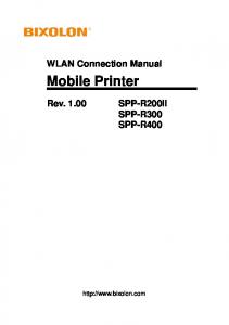
Emerging dual-mode mobile terminals could provide flexibility and system performance enhancement by providing seamless roaming between WWAN and WLAN. The authors propose a novel integrated WWAN/WLAN twohop-relay architecture that both enhances the system capacity of existing WWAN systems and extends system coverage of WLAN terminals.
2
Next-generation wireless systems (4G and beyond) are envisioned to provide ubiquitous high-speed access over heterogeneous radio technologies. The integration of cellular WWANs and WLANs has drawn considerable attention from the research and commercial communities (e.g., 3G+802.11). Emerging dualmode mobile terminals could provide flexibility and system performance enhancement by providing seamless roaming between WWANs and WLANs. In this article we propose a novel integrated WWAN/WLAN two-hop-relay architecture that both enhances the system capacity of existing WWAN systems and extends the system coverage of WLAN terminals. The proposed two-hop-relay architecture can be considered as a system-level macro diversity technique that utilizes temporal channel quality variation to achieve increased system capacity. Significant capacity gain is achieved with the proposed twohop-relay architecture in both a fixed-rate uplink CDMA system and a variable data rate downlink HDR-like system.
INTRODUCTION Historically, the cellular network architecture has been the standard for wireless and mobile communications. In this article we investigate a compelling mobile network architecture: the integration of wireless wide area networks (WWANs) and wireless local area networks (WLANs) that exploits the capabilities of emerging dual-mode (WWAN/WLAN) mobile terminals to significantly increase total system throughput. In a cellular WWAN, mobile terminals establish radio frequency links with the centralized base station (BS), and the BS establishes global connectivity through the radio access network that connects to the backbone core network. Recently, another mobile network architecture, the ad hoc network, has emerged as an important wireless and mobile communications paradigm. In a mobile ad hoc network, mobile terminals establish connections in a distributed peer-to-peer fashion. The source mobile terminal finds a valid multihop relay connection
1536-1284/04/$20.00 © 2004 IEEE
to the destination node using mobile ad hoc routing protocols. The mobile ad hoc network architecture has some very attractive features that distinguish it from the classic cellular architecture: self-organizing, infrastructure-free (for terminal-to-terminal connections within the local ad hoc network), and dynamic adaptation to the fast-changing wireless and mobile environments. When a cellular network is combined with a mobile ad hoc network, several interesting opportunities arise [1–12]. The approach to network engineering could be substantially different, both from the cellular and mobile ad hoc network’s points of view. From the cellular network model perspective, adding mobile multihop relay capability to a cellular network can increase system service coverage and may also increase system capacity (especially for data). The system then becomes an enhanced cellular system with an alternative relaying capability to communicate with the BS. Mobile terminals with poor signal reception can benefit from the alternative multihop relay path; this could provide greater throughput or better quality of service (QoS). Similarly, replacing a long-range high-power transmission with several short-range low-power relay transmissions could reduce energy consumption for mobile terminals. Load balancing can also be achieved through multihop relay [6–8]. The ad hoc GSM cellular system (A-GSM) [4] and opportunity-driven multiple access (ODMA) [5] are two proposed cellular systems that support multihop wireless relay. A-GSM adds the relay capability to a second-generation GSM network to enhance system coverage. The ODMA proposal to the Third Generation Partnership Project (3GPP) provides a relaying protocol to enhance cellular coverage and reduces radio transmission power in Universal Mobile Telecommunications System (UMTS) Terrestrial Radio Access (UTRA) time-division duplex (TDD). Instead of integrating cellular networks with wireless multihop networks, we propose a novel two-hop-relay architecture to integrate WWAN and WLAN for capacity enhancement. More specifically, we are interested in the special but quite practical case where a WWAN and WLAN, as shown in Fig. 1, form a two-hop-relay commu-
IEEE Wireless Communications • April 2004
nication system thath enhances system coverage and capacity. From the single-hop WWAN cellular link between mobile terminals and the BS, mobile terminals could relay traffic through a WWAN/WLAN dual-mode relay gateway that connects the end user with a WLAN radio interface while communicating with the BS with a WWAN interface. The relay gateway can be a relay node placed by a wireless carrier or a dualmode mobile user. The WWAN/WLAN integration framework we consider here could discover and utilize better quality radio channels in cellular networks to achieve greater system throughput while not introducing protocol complexity in multihop routing. As Fig. 1 shows, a poorly served mobile node (MN) can receive data from the high-speed two-hop-relay link. Dead spots in cellular networks could be effectively eliminated through the WWAN/WLAN two-hop-relay scheme. The WWAN/WLAN two-hop-relay scheme also extends the system coverage and facilitates the deployment of WLANs. In heterogeneous wireless access networks, WWAN cellular networks coexist with WLAN access point deployment (e.g., 3G+802.11). For dual-mode terminals, ubiquitous wireless access can be achieved by seamless roaming between WWANs and WLANs [13]. However, for terminals with only a WLAN interface, the coverage area is limited to the neighborhood of the access points (APs), as shown in Fig. 2a. With the two-hoprelay scheme, the WLAN coverage area is extended to locations with dual-mode relay gateways (denoted RG in Fig. 2b). The single-mode 802.11 mobile terminals can also benefit from increased system coverage.
WHY NOT MULTIHOP? In contrast to many other multihop network architectures, we focus on a relay scheme that limits packet forwarding to one hop. There are several practical reasons to employ this two-hoprelay approach. The rationale behind the twohop-relay design is to reduce system complexity, avoid inefficient mobile ad hoc routing, reduce the impact of inefficient random medium access protocols, and alleviate the congestion bottleneck at the Internet gateway nodes.
Poor WWAN link Good WWAN link WLAN
Dual-mode relay gateway
WWAN BS
Mobile node
■ Figure 1. The two-hop-relay architecture for WWAN (e.g., 3G or 4G cellular) and WLAN (e.g., 802.11) integration.
The Internet-connected wireless multihop networks, along with the proposed two-hop-relay scheme, face the same formidable task of alleviating the congestion bottleneck at the global Internet gateway. The gateway, which connects the global Internet and the local wireless multihop network, easily becomes the bottleneck when most of the traffic goes through a single node. As the literature demonstrates [3], the capacity of one wireless ad hoc network depends on the percentage of global traffic of this network. The multihop network capacity is greater than the traditional single-hop cellular network when traffic flows are dominated by local peerto-peer applications. The spatial spectrum reuse results in a substantial increase in network capacity. Nevertheless, it may not be the same when most traffic is incoming from the global Internet or outgoing traffic is destined for some nodes outside the wireless ad hoc network domain. The capacity of wireless ad hoc networks significantly decreases when the incoming or outgoing global traffic dominates. The gateway inevitably becomes the traffic bottleneck. The computational capability of the gateway, link bandwidth between the gateway and the Internet, and sometimes the bandwidth and computational capability of intermediate relay nodes around the gateway limit the overall system capacity.
AP
AP
RG RG RG
AP
BS
(a) WWAN coverage area
RG AP
BS
(b) WLAN coverage area
■ Figure 2. WLAN coverage area with WWAN/WLAN integration: a)seamless roaming; b) two-hop-relay.
IEEE Wireless Communications • April 2004
3
Relay gateway
Mobile node
1 Relay advertisement
2
Relay request
3
Cellular network
Registration (cellular)
Relay request 4 Authentication, registration and session key agreement
Relay reply Relay initiation
5
6
Application
■ Figure 3. Message flows of two-hop-relay access discovery. Mobile ad hoc routing protocols are required to discover the multihop relay routes from the source nodes to the destination nodes. Since routing in mobile ad hoc networks is distributed, mobile ad hoc routing protocols primarily rely on mechanisms that are based on flooding to discover a new route when there is no previous record in the route cache. Due to node mobility and radio signal strength fluctuation, the routing path from the source node to the destination node could easily become invalid. Frequent route changes and the resulting route discovery procedures could cause high signaling overheads. Multihop forwarding also results in a greater time delay between mobile terminals and the gateway. The proposed two-hop-relay scheme does not have the same delay latency issue since there is only a one-time WLAN transmission and one-time WWAN transmission. There is less route change and route discovery in the twohop-relay environment. The WWAN/WLAN two-hop-relay technique is an uncomplicated yet powerful approach to enhance the cellular system, while avoiding the packet delay, signaling overhead, and system complexity in mobile ad hoc routing schemes. Not only does a wireless multihop network face the formidable challenge of distributed mobile ad hoc routing, it also suffers from the inefficient link-layer medium access protocols. In a distributed environment, it is extremely difficult to compute a time-division schedule without compromising system performance with a heavy handshaking control overhead. The node mobility and dynamic nature of wireless communications also increase the difficulty of scheduling at the medium access layer. Wireless random access medium access control (MAC) is required in mobile ad hoc networks. Random access MAC utilizes control handshaking and backoff mechanisms to avoid packet collision. For example, the
4
IEEE 802.11 WLAN standard utilizes the RTSCTS-DATA-ACK four-way handshake to accomplish collision avoidance. In contrast to time-division multiple access (TDMA) or codedivision multiple access (CDMA) in a structured cellular network, the random access MAC that is used in distributed wireless network is inefficient in spectral resource utilization. In multihop ad hoc networks, sending one packet from source to destination generally takes several relay steps at intermediate nodes. In each of the relay steps, transmitters need to make sure the shared medium is idle with the help of random access MAC protocols before transmission. This increases the end-to-end latency and impairs radio resource utilization. When request to send/clear to send (RTS-CTS) random access is used in multihop scenarios where most traffic goes through the gateway, the exposed terminal problem will be intensified and will enlarge the level of congestion at the gateway. IEEE 802.11 has been reported to not perform well in multihop relay environments [14]. The BS can efficiently allocate radio resources to cellular terminals and intermediate relay nodes. There is only one WLAN hop that suffers from the inefficient random access medium access.
RELAY SERVICE DISCOVERY In the WWAN/WLAN two-hop-relay system, mobile terminals are required to exchange channel quality information with neighboring mobile terminals. The two-hop-relay service discovery control signaling flows are shown in Fig. 3. In the figure, the cellular network (CN) denotes a generic WWAN. It can be a 2G GSM network or one of the 3G cellular networks such as UMTS or cdma2000 or 4G cellular. The actual signaling message flows may be slightly different from one cellular network standard to another. In addition, some operations performed in the CN shown in the figure may actually be performed in several nodes within a CN rather than at only one single point. These operations may be performed at the network edge (e.g., BS and mobile switching center, MSC) or a distant location (e.g., home location register, HLR, and authentication center, AuC). For the sake of simplicity, we use a single icon to represent the whole cellular network and concentrate on the two-hop-relay scheme. The intermediate node, the relay gateway (RG), is the dual-mode node that has both WWAN and WLAN radio interfaces. For instance, the RG can be a mobile terminal that voluntarily performs the RG functionality. Cellular network carriers can provide incentive pricing and radio resource allocation schemes to encourage mobile terminals to relay cooperatively (recognizing that such mobiles will have bigger battery drain). On the other hand, cellular network carriers can also deploy dual-mode gateways to improve system performance. The mobile node (MN), shown in the figure, can be a dual-mode terminal or a WLAN-only terminal. However, we do require that the MN subscribe to the integrated service through the cellular service provider, or have a roaming agreement with the cellular service provider so that the MN can be authenticated
IEEE Wireless Communications • April 2004
0 0 1 2 3
1 4 5 6 7 8 9 0 1 2 3 4 5
Type
RM
Reserve Gateway ID Base station ID
2 3 6 7 8 9 0 1 2 3 4 5 6 7 8 9 0 1 BI type
BI value
(IP address) (IP address)
■ Figure 4. Relay advertisement message. and authorized by the CN. First, the RG must be authenticated and registered with the WWAN cellular networks before the RG establishes any two-hop relay connection for the MN. The registration process follows the general cellular registration procedures, and it depends on the types of cellular systems. For example, in the Mobile-IP-based cellular networks, the registration procedure is to start the basic Mobile IP registration with the Registration Request message. During the registration process, the RG should inform the home agent (HA) that it would serve as the RG. We introduce a new RG bit in the Mobile IP Registration Request message that indicates the intention and capability of the MN to serve as an RG. The registration of being an intermediate RG is necessary to obtain the corresponding access authorization. It may also result in different pricing policies for an RG and a non-gateway MN. After finishing the Mobile IP registration process, the RG is attached to the cellular network, and can utilize the global Internet connectivity for its own applications through the WWAN link. The RG periodically broadcasts the Relay Advertisement message through its WLAN radio interface. The Relay Advertisement message, as shown in Fig. 4, includes the current BS identification number (BSid), gateway identification number (GWid), bandwidth indicator type (BI-T), bandwidth indicator value (BI-V), and registration method (RM) fields. The BSid identifies the serving BS in the cellular network. The GWid is used to identify RG nodes in the same serving BS. In a traditional cellular network, the MSC stores and manages a set of GWids for each BS and assigns the GWid during the cellular network registration. In an all-IP wireless cellular network, the 4-byte IP address of the BS is used as the BSid. The 4-byte IP address of intermediate relay nodes is used as the GWid. The foreign agent (FA) will maintain a mapping table that contains the corresponding BSid and GWid. Generally, the BI-V field indicates the data rate per mobile terminal that the gateway and the BS can support. However, the BI-V field could be filled with QoS or any other system performance metrics. The BI-T field determines the format of the BI-V in this signaling message. The RM field shows whether the mobile terminal is required to register directly through the cellular link or can be registered through the WLAN link, when these two methods are both available. The third step starts when the MN receives a
IEEE Wireless Communications • April 2004
Relay Advertisement message and decides to connect via two-hop-relay rather than a singlehop cellular link. A dual-mode MN can compare the channel state information of its direct WWAN connection and the Bandwidth Indicator value in the received Relay Advertisement message to decide whether establishing a direct cellular connection or a two-hop-relay connection. The power consumption of direct communication and two-hop-relay, mobility pattern of the terminal, and time constraints of applications are also possible factors involved in the decision process. When the MN is a dual-mode terminal, the MN sends the Relay Request to the RG after comparing the pros and cons of the two-hoprelay. When the MN only has a WLAN radio interface, the MN has no other choice but sends the Relay Request to the RG right after receiving Relay Advertisement message. The RG stores the identification of the MN, which can be the IP address in the all-IP wireless networks or the IMSI in GSM or UMTS systems. Then RG forwards the Relay Request to the CN and waits for the authentication result and authorization from the cellular network. The authentication and authorization identity in the CN differs from one system to another. For example, in the integrated IEEE 802.11/3G integrated environment, the authentication, authorization, and accounting (AAA) server can get the subscription information from the HLR/AuC to see if the mobile user are eligible for the two-hop-relay service. Step 4 involves several signaling messages for the MN to register with the CN. During the registration process, the MN and CN mutually authenticate each other, and the CN checks the subscription profile of the MN. After authentication, the MN and network should generate the cipher key and integrity key that are going to be used. In step 5, the CN sends the Relay Reply message. The RG notifies the MN whether the relay service is authorized or declined. This figure shows the scenario when the CN authorization is successful. The RG sends out the Relay Initiation message to notify the MN to start the actual applications. When the MN receives the Relay Initiation, it can start the applications, which are secured by the session key suite negotiated during step 4.
IEEE 802.11 has been reported to not perform well in multihop relay environments. The BS can efficiently allocate radio resource to cellular terminals and intermediate relay nodes. There is only one WLAN hop that suffers from the inefficient random access medium access.
SYSTEM PERFORMANCE EVALUATION The WWAN/WLAN two-hop-relay architecture can be applied to any WWAN cellular and
5
HDR system capacity
HDR system capacity 2500
1400
Throughput (kb/s)
1200
Overall system throughput (kb/s)
R50 R100 R150 R200 HDR
1000 800 600 400
2000
1500
Relay Lmax/Lmin = 1 Relay Lmax/Lmin = 4 Hdr Lmax/Lmin = 1 Hdr Lmax/Lmin = 4
1000
500
0
200 1
2
3 4 5 6 Latency ratio = Lmax/Lmin
7
20
8
80 40 60 Mobile node number per sector
(a)
(b)
HDR downlink: WLAN range = 100 m
HDR downlink: WLAN range = 200 m 2000 Overall system throughput (kb/s)
1000
800 Throughput (kb/s)
100
600
400 Relay Lmax/Lmin = 1 Relay Lmax/Lmin = 4 Hdr Lmax/Lmin = 1 Hdr Lmax/Lmin = 4
200
0 0
1500
1000
Relay Lmax/Lmin = 1 Relay Lmax/Lmin = 4 Hdr Lmax/Lmin = 1 Hdr Lmax/Lmin = 4
500
0
2 4 8 10 6 Lognormal shadowing standard deviation (dB)
12
0
(c)
2
4 6 8 10 Lognormal shadowing standard deviation
12
(d)
■ Figure 5. The performance of the downlink HDR system. WLAN integration. We choose to simulate the likely scenarios of a 3G cellular system and IEEE 802.11 WLAN integration. The WLAN system uses a random access MAC protocol and supports a much higher data rate than the WWAN system. As is the case in practice, we assume that the wireless spectrum of the WWAN system does not overlap with the spectrum of the WLAN system so that the radio signals of the WLAN system and the WWAN system will not interfere with each other. We study two types of systems: a downlink variable data rate system and an uplink fixed data rate CDMA system. The downlink case conforms to the traffic pattern in emerging data applications such as Web browsing. The performance evaluation settings emulate the cdma2000 high-data-rate (HDR) system [15] in the downlink scenario. The uplink case represents a generic scenario where fixedrate voice services are transmitting over the CDMA system. All of the active mobile nodes transmit toward the cellular BS with the same transmission rate. The uplink power control is used in order to avoid the near-far effect. The overall throughput of a cell is the performance metric to evaluate both scenarios. However, the computation method of the trans-
6
mission rates will not be the same due to differences in the nature of these two systems. For a downlink HDR system, we follow parameters described in [15]. We assume precise power control in the uplink CDMA simulation. The throughput is measured based on the Shannon capacity formula with a capacity gap gC, which is defined as the difference between the ideal upper bound and the capacity of the current system. We set g C = 3 dB for computation. The radio propagation model considers both path loss and shadowing effect. The path loss exponent is assumed to be n = 4. The shadowing effect is modeled by the conventional lognormal random process with standard deviation σ = 8 dB. The WWAN cellular system consists of three-sector microcells with 1000 m radius. Unless otherwise specified, there are 50 dualmode terminals per sector. The default WLAN transmission range is set to 200 m.
DOWNLINK HIGH-DATA-RATE SYSTEM PERFORMANCE Wireless LAN Transmission Range — First, we demonstrate the performance of the original HDR sys-
IEEE Wireless Communications • April 2004
tem and the HDR-based two-hop-relay system with different delay latency ratios [15]. The HDR delay latency ratio (Lmax/Lmin) is defined as the maximum user delay among all HDR users divided by the minimum user delay among all HDR users. Since wireless radio resources can be allocated unevenly in HDR systems, Lmax/Lmin represents the unfairness in an HDR system. The HDR system allocates radio resources so as not to violate the delay latency ratio constraint, while maximizing overall system throughput. In Fig. 5a the original HDR without WLAN relay is denoted as HDR while other two-hop-relay systems are labeled with different WLAN relay ranges. For example, the system with 100-m WLAN range is labeled R100. Both the original HDR system and the HDR-based two-hop-relay systems achieve greater throughput as the delay latency ratio Lmax/Lmin increases. The system capacity gain of the two-hop-relay system increases as the WLAN transmission range increases. Provided that the mobile terminal density remains the same, the greater the WLAN range, the higher the probability of finding a better intermediate relay node. Two-hoprelay with 50-m WLAN range outperform the original HDR system about only 5–6 percent because it is difficult to find other relay candidates within the short 50-m range. Even if a mobile terminal can possibly find another mobile terminal within the 50-m radius, the distances from both terminals toward the BS are about the same and the radio signal attenuations due to path loss are around the same level. Thus, the radio channel conditions of these two terminals are merely determined by the shadowing effect and have a greater chance to be in the same state. As the WLAN transmission range increase to 100 m, the capacity gain of the WWAN/ WLAN relay reaches the 28–35 percent region. For wide-range WLAN scenarios, the two-hoprelay system capacity increases significantly. Using a 150-m radius WLAN to relay for an HDR system can achieve a 55–75 percent capacity gain. While we further increase the WLAN transmission range to 200 m, the throughput in the two-hop-relay system is more than doubled from the original HDR system. The two-hoprelay system capacities range from 200 to 400 percent of the original HDR system capacities. Variable rate data applications can benefit significantly from the two-hop-relay mechanism. Mobile Terminal Density — As shown in Fig. 5b, the overall system throughput will increase with the number of mobile terminals in the two-hop WWAN/WLAN relay system. In the original HDR system, given the same delay latency ratio, the mobile terminal density has no effect on the overall throughput. While the per-user data rate distribution is independent of the number of mobile terminals in the system, the ratio of the time slots assigned to high data rate users to the amount over the time slots assigned to low data rate users should be kept the same regardless of mobile terminal density. On the other hand, the greater mobile terminal density causes the greater possibility that a low-data-rate mobile terminal can find a high-data-rate mobile terminal to relay. Hence, the overall system capacity
IEEE Wireless Communications • April 2004
of the two-hop-relay system benefits from the increasing number of mobile terminals. Radio Channel Conditions — The shadowing effect, which is characterized by the lognormal random distribution, reduces the HDR-based system performance in most of the cases. When σ, the standard deviation of the lognormal random variable, increases, which implies that the volatility of the radio channel quality increases, the throughput of the HDR system decreases. Nonetheless, the relative system capacity percentage gains increase steadily when the radio signal quality varies more severely. As σ increases, the supported user data rates spread in a wide range; hence, the chance that a low-data-rate user can find a high-data-rate user increases. Therefore, the lognormal random shadowing causes better opportunities to find an intermediate relay gateway with better WWAN connection quality. This is analogous to the multipath fading scenario in wireless communications but at a different system protocol layer, with different scopes of dynamic wireless channel quality variation. Diversity techniques, such as selective combing signals transmitting in different radio paths, can achieve better system capacity under multipath fading. This two-hop-relay scheme can be considered as a macro diversity technique, which utilizes the channel state variation in different WWAN connections to achieve better system performance. The achievable capacity gain depends heavily on the radio propagation environment in various deployment scenarios. The two-hop-relay technique is more effective when the WLAN communication range is greater than the coherence distance of the shadowing effect. Wireless service providers can build dual-mode relay stations with proper capacity planning to improve system performance (e.g., outdoor-toindoor environment).
Mobile terminals at the boundary of cells result in greater interference to neighboring cells. The two-hop-relay architecture minimizes the transmission of high-power CDMA cellular signals and thus reduces adjacent channel MAI interference in other cells, thus improving system capacity.
UPLINK CDMA PERFORMANCE The multiple access interference (MAI) is the chief limiting factor in CDMA-based networks. Mobile terminals at the boundary of cells result in greater interference to neighboring cells. The two-hop-relay architecture minimizes the transmission of high-power CDMA cellular signals and thus reduces adjacent channel MAI interference in other cells, thus improving system capacity. Figure 6 demonstrates the two-hop-relay throughput in a CDMA-based system. Capacity typically increases 10–40 percent in a CDMA system. The capacity gain is less significant compared with an HDR-based system, since poor signal reception is alleviated by power control in a CDMA system. As the expected number of relay nodes with better signal quality increases, capacity gain increases. Similar to previous HDR results, a two-hop-relay system has greater capacity with high mobile terminal density, long WLAN radio transmission range, and variable radio channel conditions.
CONCLUSION In this article we propose a two-hop-relay architecture to integrate WWAN cellular and WLAN for next-generation wireless systems. The two-
7
750
750 Cellular Relay
Cellular Relay 700 Throughput (kb/s)
Throughput (kb/s)
700
650
600
550
650
600
550
500
500 50
0
100
0
100
Number of active mobile nodes
300
200
Wireless LAN range (m)
(a)
(b)
700
700 Cellular Relay
Cellular Relay
650 Throughput (kb/s)
Throughput (kb/s)
600 600
550
500
400
500
450
300 0
5
10
2
Standard deviation of log-normal shadowing (c)
2.5
3
3.5
4
Path loss exponent (d)
■ Figure 6. The performance of the uplink CDMA system.
hop-relay technique can be considered as a powerful system-level macro diversity technique, which takes advantage of the wireless channel variation. Dual-mode mobile terminals in good channel conditions provide better-quality WWAN links to nearby mobile terminals in bad channel conditions. The overall system throughput improves with the cooperation of mobile terminals that collect and utilize the channel state information. The WWAN/WLAN two-hop-relay scheme substantially boosts the capacity of cellular networks under a broad range of conditions. The system capacity increases 10–40 percent in an uplink fixed-rate (voice) CDMA system. In a downlink dynamic-rate system, the improvement is quite substantial, and the overall throughput capacity gain is about 200–400 percent. This approach also brings additional service coverage to WLAN-only terminals in the integrated deployment scenario. Without handling the difficulties that generic multihop routing cause, the two-hop-relay scheme retains low system complexity while significantly improving system performance.
8
REFERENCES [1] R. Ananthapadmanabha, B. S. Manoj, and C. S. R. Murthy, “Multi-Hop Cellular Networks: The Architecture and Routing Protocols,” IEEE Int’l. Symp. Pers., Indoor and Mobile Radio Commun., 2001. [2] T. J. Harrold and A. R. Nix, “Intelligent Relaying for Future Personal Communication Systems,” IEE Colloq. on Capacity and Range Enhancement Tech. for the 3rd Generation Mobile Commun. and Beyond, 2000. [3] H.-Y. Hsieh and R. Sivakumar, “Towards a Hybrid Network Model for Wireless Packet Data Networks,” 7th Int’l. Symp. Comp. and Commun., 2002. [4] G. Neonakis Aggelou, and R. Tafazolli, “On the Relaying Capability of Next-Generation GSM Cellular Networks,” IEEE Pers. Commun., vol. 8, 2001, pp. 40–47. [5] T. Rouse, S. McLaughlin, and H. Haas, “Coverage-capacity Analysis of Opportunity Driven Multiple Access (ODMA) in UTRA TDD,” 2nd Int’l. Conf. 3G Mobile Commun. Tech., 2001. [6] H. Wu et al., “Integrated Cellular and Ad Hoc Relaying Systems: iCAR,” IEEE JSAC, vol. 19, 2001, pp. 2105–15. [7] X. C. Wu, S.-H.G., B. Mukherjee, “MADF: a Novel Approach to Add an Ad-Hoc Overlay on a Fixed Cellular Infrastructure,” IEEE Wireless Commun. and Net. Conf., 2000. [8] A. N. Zadeh et al., “Self-organizing Packet Radio Ad Hoc Networks with Overlay (SOPRANO),” IEEE Commun. Mag., vol. 40, 2002, pp. 149–57. [9] Y.-D. Lin and Y.-C. Hsu, “Multihop Cellular: a New Architecture for Wireless Communications,” IEEE INFOCOM, 2000. [10] H. Li et al., “Multihop Communications in Future
IEEE Wireless Communications • April 2004
Mobile Radio Networks,” IEEE Int’l. Symp. Pers., Indoor and Mobile Radio Commun., 2002. [11] B. Walke and G. Briechle, “A Local Cellular Radio Network for Digital Voice and Data Transmission at 60 GHz,” Proc. Int’l. Conf. Cellular and Mobile Commun., London, U.K., Nov. 1985. [12] V. Sreng, H. Yanikomeroglu, and D. D. Falconer, “Relayer Selection Strategies in Cellular Networks with Peer-to-Peer Relaying,” IEEE VTC Fall 2003, 2003. [13] H. Luo et al., “Internet Roaming: A WLAN/3G Integration System for Enterprises,” Proc. Asia-Pacific Optical and Wireless Commun. — Wireless and Mobile Commun. II, 2002. [14] S. Xu and T. Saadawi, “Does the IEEE 802.11 MAC Protocol Work Well in Multihop Wireless Ad Hoc Networks?,” IEEE Commun. Mag., vol. 39, 2001, pp. 130–37. [15] P. Bender et al., “CDMA/HDR: a Bandwidth Efficient High Speed Wireless Data Service for Nomadic Users,” IEEE Commun. Mag., vol. 38, 2000, pp. 70–77.
BIOGRAPHIES HUNG-YU WEI (
[email protected]) received a B.S. in electrical engineering from National Taiwan University in 1999, and an M.S. in electrical engineering from Columbia University in 2001, where he is currently working toward a Ph.D. degree. His research interests are in the area of wireless and mobile networks.
Without handling the difficulties that generic multihop routing cause, the two-hop-relay scheme retains low system complexity while significantly improving the system performances.
RICHARD D. GITLIN [F] (
[email protected]) is currently vice president, technology of NEC Laboratories America. Before assuming this position he was a visiting professor of electrical engineering at Columbia University. After receiving his doctorate in electrical engineering from Columbia, he was with Lucent Technologies for more than 32 years, where he held several senior executive positions. He is the co-recipient of the 1995 IEEE Communications Society Steven O. Rice Award, the 1994 IEEE Communications Society Frederick Ellersick Award, and the 1982 Bell System Technical Journal Award. He is an AT&T Bell Laboratories Fellow.
IEEE Wireless Communications • April 2004
9


![Gigaset SE366 WLAN - Wireless Driver & Software [PDF]](https://m.moam.info/img/260x300/gigaset-se366-wlan-wireless-driver-software-pdf_647a16be098a9ea8128b4625.jpg)