Workflow-based applications by F. Leymann D. Roller
A significant number of companiesare reengineering their business to be more effective and productive. Consequently, existing applications must be modified, and new applications must be written. The new applications typically run in adistributed and heterogeneous environment, performing single tasks in parallel, and demanding special transaction functionality for the supporting environments. Workflow-based applications offer this type of capability. In this paper, their principal advantages are derived and set in context to transaction, object, and CASE (computer-assistedsoftware engineering) technology. In particular, a method is proposed to develop these workflow-based applications in a cohesive and consistent way.
B
usiness re-engineering is one of the most important topics on theagenda of a large number of companies. It has been triggered by a changing business environment that requires companies to be more flexible andto react faster. New processes are defined; existing ones are changed or even abandoned. These processes are no longer only intraenterprise processes, such as claims processingin an insurance company or loan processing ina bank. Multiple enterprises are connecting their tasks together in interenterprise processes to more efficiently manage their own processes. The orderactivity in a production planning process for a car company, for example, starts the appropriate orderentry process at a parts supplier. Companies may even use common processes to tie together parts of their various companies to form virtual companies,foreseen as by NIIIP (National Information Infrastructure Initiative).* 102
LEYMANN AND
ROLLER
Business processes not only deal with customers; internal administrative processesare also businessprocesses. A typical example of such an administrative process is the handling of an expense account form. An employee fills in the proper information; the form is routed to the employee’s manager for approval and then on to the accounting department to disburse the appropriate check and mail to it the employee. Backing up and restoring databases as performed by database administrators another is administrative process. One of the key objectivesof the re-engineered business processes is to minimize the time required for execution. In a well-defined businessprocess, therefore, all unnecessary tasks have been eliminated, and all tasks are performed with the highest degree of parallelism possible. These tasks can be performed by different people. Coincidentally,different equipment with different software is used to perform the tasks. Thus those business processes are run in a distributed and heterogeneous environment. Workflow management systems (WFMSS) provide the foundation for defining and executing businessprocesses. Wewill refer to applications built according to the workflow paradigm as workflow-basedapplications. The creation of workflow-based applications needs a special developmentmethod, which we callprocessbased CASE (computer-assisted software engineerQCopyright 1997 by International Business Machines Corporation. Copying in printed form for private use is permitted without payment of royaltyprovided that (1) each reproduction is done without alteration and (2) the Journal reference and IBM copyright notice are included on the first page. The title and abstract, but no other portions, of this paper may be copied or distributed royalty free without further permission by computer-based and other information-service systems. Permission to republish any other portion of this paper must be obtained from the Editor.
0018-8670/97/$5.00 0
1997 IBM
IBM SYSTEMS JOURNAL,
36, VOL
NO 1, 1997
~~
~
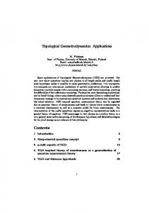
Evolution of applicationstructures
Figure 1
r APPLICATION SYSTEM
APPLICATION SYSTEM
APPLICATION SYSTEM
r
I
I
1 0..
1
DATABASE MANAGEMENT SYSTEM DATABASE MANAGEMENT SYSTEM
!
1 WO PROCESSING 2
1 ... . .
3
..
ing). The method we are proposing in this paper provides a consistent wayof developing this kind of application. Themetaphor fundamental to this method is the two-level programming paradigm of workflow technology, in whichprogramming in the small is delivered through visual builders, and programming in the large is deliveredvia businessmodeling tools and workflow build time. The next sectionintroducesthe notion of a workflowbased application by revealing the impact of database and workflow technology on the structure of applications.The subsequent section summarizesthe benefits of workflow-based applications. Then the following section sketches some relations and synergy between workflow technology and object technology. The section after that outlines an application developer’s wish list for a development environment that helps to efficiently design, implement, and monitor workflowbased applications, and the succeeding section provides a blueprint of the componentsof such an environment. That section is followedby one showing some aspects of testing of workflow-based applications without requiring the setup of a complex environment, and then a simple exampleof how such an environment could IBM SYSTEMSJOURNAL,
VOL 36, NO 1, 1997
work is given. The last section outlines the transaction management features of a workflow management system desirable for further enhancing the flexibility of workflow-based applications.The paper concludes with a summary. The notion of workflow-based applications
Figure 1 shows the fundamental steps in the evolution of the structure of application systems. As depicted in part l of the figure, the first application systems builtwere large monolithical pieces of code with some internal structuring. The internal structuring reflected the pieces of infrastructure code that had to be built by the application developers, in addition to thepieces of code that implemented the actual logic of the application. Removal of data dependency. The lower boxes of part 1reflect some pieces for accessing data. These pieces include,for example, the handling of data sets, such asopening and closing anaccount file, performing the actual physical input and output operations via the appropriate110 routines provided by the operating system, such as reading an account record, LEYMANN AND ROLLER
103
or interpreting the dataretrieved according to some inline mappinginformation, such asthe location and the type of the account number.
Any change to the schema of the data, such as the addition of a field to a record or a change of access path to the data, requires all applications that accessed the record to bechanged and the data to be migrated. Therefore, these applications are data dependent. To reduce data dependency, each application system introduced its own files holding redundant cop-
Workflow management systems support the definition and execution of business processes.
A change in the assignment of tasks to people, commonly referred to as staff a~signment,~ in the execution sequence of the application logic blocks, or the addition of a field to be passed between the blocks, requires the application to be changed. Applications are flow dependent. These changes are cumbersome and generally cannot be performed fast enough. In addition, the actual structure of the business process is not known to nonprogrammers. This situation becomes worse with the increasing demand to adapt to market needs that are changing ever faster.
As a consequence, database management systems (DBMSS) were de~eloped.~ Their purpose was to support the definition and concurrent manipulation of data. Many changes to the dataschema and access paths, for example, can now be done without impacting the related programs. The body of data becomes a property in its own right; it becomes a corporate asset. Consequently, the structure of applications changed to the structure depicted in part 2 of Figure 1.
Workflow management systems were developed to help overcome these problems. Their purpose is to support the definition and execution of business processes. That means that thedefinition and execution of the appropriate control and data flow, the assignment of people to tasks, and the invocation of the application logic blocksare externalized. By definition, changes to the process can now be done without impacting the application logic blocks.The process becomes a property in its own right-it becomes a corporateasset.’ The structure of the applications changes to thestructure depicted in part 3. The application becomes a workJow-based applicationconsisting of a model of the underlying business process anda set of (flow-independent) applicationlogic blocks. The abstractions of the elementary pieces of work ina business process are called activities; the concrete realizations of these abstractions at process execution time are referred to as activity implement a t i o n ~The . ~ application logic blockscorrespond exactly to these activity implementations in a WFMS environment.
Removal of flow dependency. The boxes depicted in the middle of each of the three parts are the application logic blocksthat contain the actual application functions and business algorithms. The top boxes inpart 1and part 2 show some pieces that are required to put these application logic blocks together in a form prescribed by the application. To use a banking application as an example, it would
The capability of the workflow management system to support the definition and execution of control and data flow, the assignment of activities to people, and the invocation of the activity implementations associated with such an activity is not limited to splitting up large monolithical applications. It allows the various activities to be distributed to different computers with different systems. Different
ies of the “same” datawith the well-known consequences of jeopardizing data consistency. The management of the information about the data, such as which data are maintained and where the data are used, is alsocumbersome.This situation became worse over time with the increasing amount of information.
104
include bringingthe blocks into the correct sequence to first withdraw moneyfrom one account and then deposit it into another account, or passingthe proper data from one block to the next so as to pass the amount of money to be transferred from the withdraw blockto the deposit block, or assigningthe right person to a task based on application-specific criteria such as the authority of the account owner.
LEYMANN AND ROLLER
IBM SYSTEMS JOURNAL, VOL 36, NO 1 , 1997
systems may mean different operating systems supported by the same workflow management system or may mean different workflow management systems. Workflow-based applications are, therefore, by nature distributed, heterogeneous applications. The fundamental benefits of workflowbased applications
In this section the following four fundamental benefits inherent to workflow-based applicationsare discussed: Flexibility in changing the model of the underlying business process Integration capabilities for even disparate applications Reusability of activity implementations and process models Scalabilityof application development and execution Flexibility. The first benefit is based on the two-level programming paradigm underlying workflow-based applications.The specification of all flowrelation information is, as was already described, separated from the specification of the logic of the application functions, that is, the algorithmic aspects of the application. This separation allows the model of the process underlyingthe subject applicationsto change without affecting the associated activity implementations. It is the predominant reason why enterprises are investing in workflow technology today. Integration. The second benefit is based on multiple features.
First, the ability of a WFMS to persistently store the workflow-related execution context of each activity implementation (that means the containers4) and the supported share it between different activities via data flow features allows for an integration of activity implementations that is differentfrom the current standard approach of accessing a joint database. Second,transaction features tailored toward support in WFMSS have been proposed (for example, see References 7, 8, 9, 10, and 11) to especially allow the integration of activity implementations that are acDBMSs into atomic units (in the sense cessing different of “all or nothing”) or compensation units (in the sense of “joint compensation”); see the last section for more details. IBM SYSTEMS JOURNAL, VOL 36, NO 1, 1997
Third, the heterogeneity feature currently being worked on by the Workflow Management Coalition (W~MC)l2 and N I I I P ~strives toward support of crossenterprise business processes. That support means that each application part may even be managed by a different vendor’sWFMS. The goal isto enable “virtual enterprises” not only by supporting cross-enterprise sharing of data based on the STEP (STandard for the Exchange of Product definition data) standard (for example, see Reference 13), but also to share business processes across enterprises and to enable interoperation of workflow management systems. Reusability. The third benefit isbased on the structure of workflow-based applications themselves.As elaborated earlier, activity implementations for process models are typically flow-independent and free of assumptionsabout their usage (withthe final consequence that external transaction mechanisms are needed; see the last section). Therefore, a particular activity implementation can be used in many different process models.If both the activity implementation and the workflow manager comply with the WMC standard for “invoked applications,” the activity implementation can ultimatelybe used in many different WFMSs. As a result, the exploitation of workflow technology stimulates reuse of code with activity implementations (for proper application logic) as the granules of code reuse. Whereas the reuse of class libraries, frameworks, parts, and designpatterns is coupled with object technology (for example, see Reference 14), reuse based on workflow technology is independent of it.
’’
Furthermore, there is a strong demand for reusing process models themselves. For this purpose, many WFMSs allow for activity implementations that are realized as process models, so-called “subprocesses,” thus enabling top-down and bottom-up modeling of processes that helps stimulate the reuse of process models as subprocesses. Industry consortia such as the Object Management Group (OMG)and the Object Definition Alliance (ODA),as well as various vendors, are currently defining reusable components for the purpose of being ableto construct applicationsout of prefabricated parts. The expectation is that these components will eventually be sold as off-the-shelf components. The formation of a joint work group of the OMG and WMC indicates that these components will be specified in a manner such that they can be used as acLEYMANN AND ROLLER
105
tivity implementations within businessprocess models. This will further help to promote the paradigm of workflow-based applications.
the low-level business processes are developed and tested. This sequence facilitates the parallel development of business processes.
Similarly, industry interest groups and vendors are in the process of specifying de facto standards for models of business processes that apply to particular application domains. These process models can be reused in particular as subprocesses in enterprisespecific processes.In this context, it isinteresting to note that vendors of standard software, SAP with R/3**l5 for example, are currently describing their applications via models of business processes, making useof workflow management systems so that the application performs accordingto the process model. Workflow-based applications will thus very likely play a major role in this area, too.
Using businessobjects and reusable process models makes business process development as well as activity implementation development easier.
Scalability.The fourth benefit of workflow-based applications is their scalability interms of application development and application execution. Scalability allows workflow-based applications to be used for small applications,such asthe management of a doctor’s office, and for large applications, such as the order process in a manufacturing company involving processesof outside suppliers.At first glance,one would assume that covering sucha broad spectrum demands specialized workflowmanagement systems that have nothing in common except a few basic ideas. However, that is not the case. It seems that the development groups of workflow management system vendors strive for one system architecture and design that caters to thedemands of small and large applications.
Application development, The development of workflow-based applicationsprovides scalingthrough the underlying two-level programming paradigm, the top-down process modeling capabilities, and the reuse of process models and business objects. Developing an application in two separate levels, first, the development and test of the business process and, second, the development and test of the activity implementations, reduces the complexity of the application from a design, implementation, and testing standpoint. In particular, the parallel development of the activity implementations, made possible by the fixed interfaces to thebusiness process, provides for a faster development cycle. The support of subprocesses allows the top-down development of business processes.First, the high-level business process is developed and tested, and then 106
LEYMANN AND ROLLER
Application execution. Scaling of the application during execution is facilitated through the workflow manager’s executionenvironment: subprocessescan
Scalability allows workflow-based applications to be used for both small and large applications.
be executed on different servers; workload balancing supports exploitation of the available resources; dynamic invocation of activityimplementations(even on remote processors) provides flexibility in executingactivity implementations; and distribution of work items allows the assignment of users to servers to be balanced. Objects can benefit from workflows
Enterprises areinvesting today in object technology to improve the productivity of their programmers and toenable even non-data-processing professionals to build applicationsviavisualbuilders (described in a later section). Here we discuss some of the benefits object technology might gain from workflow technology and how workflow-based applications can be built with objects.Note thatvendors of standard software (like SAP) are also combining object technology and workflow technology (for example, see References 15 and 16). Flow-independent objects.One of the underpinnings of object technology isthe insight that robustness of a system is normally achieved by encapsulatingthings that might become subject to changes. So, for example, if the orderin whichoperations are tobe performed can change, or if operations can be added or removed, the guidelines of object technologyconsequently recommend a dedicated control object. That control object encapsulates the scheduling of IBM SYSTEMS JOURNAL,VOL
36,
NO 1,
1997
various operations. Thus, to achieve robustness via encapsulation, not only behavior and data must be taken into account (what is usually done), but also “ordering.”
pie distributed throughout an enterprise. Heavyweight scripting adds such features as parallelism, heterogeneity,distribution, and context-dependency to thenotion of scripting.The implementation overhead inherent in these features is the reason why we call this kind of scripting “heavyweight” andwhy we think two differentcategoriesof scripting havea right to exist.
If the last proposition is ignored, following the encapsulation paradigm tends to hide fragments of the proper business processes in the implementations of the objects.” In this situation not only the objects Workflows in object-oriented analysis and design. themselvesbecome flow-dependent,but transitively so does each application reusing these objects. In adObject technology provides many techniques to capdition, the business processes (being an asset by ture thedynamic behavior of an application, for exthemselves)are only partially described explicitly and ample, collaboration graphs, event flows, timing diexternalized to a broader community. In contrast, agrams, and interaction diagrams. At an abstract implementingobjects in sucha way that they become level, they havethe structure depicted in Figure 2, flow-independentwill result in component-basedapwhich wecall a message flow diagram. Basically, such plications that are much more flexible. a diagram describes the control flow between method invocations of the participating objects. Scripting and objects. Building flow-independent Reference 21 points out, based on this insight, that business objects will enforce a clear separation of structures of such diagrams the more stable behavior of the business objects from two principally different the more dynamic behavior of the business processes. can be observed (see Figure 3). Forks represent cenA business process explicitly describes the rules of tralizing responsibilities, which means that a single how, when, and by whom the services provided by object represents the global control and data flow. the various objects are exploited. An activity impleThe other objects mainly provide utilities, Such a mentation within a business process may be directly structure is preferred by workflowpurists. Stairs reprealized by invoking a method of an object. resent delegating responsibilities,which means that each object knows a few other objects and how to When the statics of a business split from its dynamexploit them. Thus, each object is responsible for the ics, the interaction between business objects is delocal control and data flow and is thus flow-depenfined by the process model. The process model may dent. Many object purists can be found who prefer be perceived as a script prescribing the use of busthis structure. Our proposition that robustness iness objects to reach particular business goals. At achieved via encapsulation must not only regard berun time,the workflow management system will manhavior and data,but also ordering, is represented by age the flow of control and data between the busforks that typicallyencapsulate ordering. In contrast, iness objects, will establish transaction boundaries stairs express an assumed stability of ordering. It is around them as defined inthe script, and will make obvious that fork and stair structures have to be used certain that the proper organizational units of the in combination to yield a stable and robust structure. enterprise become responsible for utilizing the services provided by the various business objects. Note One of the special strengths of workflow technology that languages like C+ + follow a similar philosois facilitating modifications for operation orders in an easy manner. Thus, it is only natural to exploit phy. A program consists of objects and procedural workflow technology for the implementation of fork elements explicitly describing the control flow bestructures, that is, for encapsulating the ordering of tween the method invocations of the objects. operations. Simply, the controlling object itself beIt is important to note that we do not consider workcomes an instance of a process model that in turn flows as a substitute for scripting languages such as describes the control and data flow between the afREXX, l8 Lotusscript**,l9 or Visual Basic* *.’O These fected objects. languages can be considered as lightweight scripting For this purpose, each method invocation stimulated languages very well-suited for composing desktop apby the control object becomes an activity inthe proplications for asingle end user, perhaps doneby the cess model, which finallyrepresents the control obend user. Defining a workflow canbe considered as ject. Thus, if the method m of object o is invoked, heayvweight scripting suitable for composing applications requiring the collaboration of multiple peoo m ( ) is an activity of this process model. The conIBM SYSTEMSJOURNAL,VOL
36, NO 1, 1997
LEYMANN AND ROLLER
107
Figure 2
Message flow diagram
USED OBJECTS OBJECT-3
OBJECT-2
OBJECT-1
C.
OBJECT-n
b
Figure 3
Forksandstairs
FORK
trol connectors are prescribed by the time order in which messages are sent according to the message flow diagram. If m 1 is sent to 0 I and m2 is sent to 0 2 and no other message issent to any other object in between, the flow of control is from 01.ml( ) to 02.m2( ). Based on the structure of message flow diagrams, no parallelism is exploited in the process model derived by this simplealgorithm. Typically a design phase needs to be conducted to establish a more sophisticated process model.
108
LEYMANN AND ROLLER
STAIR
At run time, the WFMS will instantiate this process model, resulting in an instance of the control object. By definition,there will be no implementation of the control object in the classical sense, for example, in C+ + : the implementation consists of the process model, which is interpreted on aper instance basis by the WFMS. Consequently, changes to theprocess model will immediately affect the implementation of the corresponding control objects instantiated after the changes. IBMSYSTEMS
JOURNAL, VOL 36, NO 1, 1997
into acollectionofsubdiagrams, each of which is either afork structure or astair structure. Fork structures can be transformed into skeletons of process models in a straightforwardmanner. Stair structures are natural candidates for modularization; that is, they can be realized as programs or as subprocesses. Application developer’s wish list
The development of workflow-based applications can be facilitated by a new approach that helps application developersin the design, implementation,and testing of those applications. We call thisapproach process-based CASE to indicate that the goal of the proposed CASE method is to create applications that are workflow-based, thus implying that the underlying businessprocess is externalized and managed by a workflow management system. This approach is different from the notion ofprocess-centeredCASE, where processes are used to develop applicationsand coordinate development teams.22In fact, processto process-based centered CASE could also be applied CASE.
I
Binary code reuse isa key factor in the success of application development productivity. Source code reuse just will not render theproductivity increase the software industry is looking for. Business objects are themain manifestation of this paradigm. Workflow allows us to define, execute, and monitor applications that move the work to be done to the desktop of the person responsible for performing a piece of the overall task. Second,the development approach must cater to the specific characteristics of workflow-based applications. It must support the design, implementation, and testing of the distribution aspects of the applications, in particular, the parallel execution of tasks. Third, it mustsupport openness through compliance with appropriate standards, including de facto standards such asCORBA (Common ObjectRequest BroOLE (Object Linking and Emker Ar~hitecture),~~ ’ ~ Lotus Notes**. bedding),2swmc, O p e n D ~ c , and Fourth, this development environment must be available on a variety of platforms.
First, the development of the applications should be supported with the set of new and evolvingprogramming paradigms, such as visual programming, the construction from parts, the usage of business objects, binary code reuse, object orientation, and, by definition, the exploitation of workflow.
And last, the components of the development environment must be tightly integrated. In particular, they must provide a cohesive, seamless, and intuitive end-user interface.
Visualprogrammingsupports the development of programs that areno longer performed by writing statements in a programming language. The program is constructed (1) by creating the advanced graphical user interface of the program by drawing the screen layouts on the screen, and (2) by visually assemblingand connecting parts to define the behavior of the program. Construction ofparts is a technology to build applications from existing,reusable software components c a l l e d p a r t ~The . ~ ~ assembly is typicallyperformed via the composition editor of the visual builder. Parts provide a wide range of capabilities, from verysimple functions through complete, highly sophisticated applications. Primitive parts can be combined to form more complex composite parts. Business objectsare becoming increasingly important as granules of reuse. Typical examples may be a customer business object or an account bus-
The essential components for the proposed environment are (1)a business modeling tool, (2) an objectoriented analysis tool, ( 3 ) a workflow management system, (4) a visual builder, ( 5 ) a databasemanagement system, (6) a databasedesign tool, and (7) object support. Figure 4 depicts those components that are exposed directly to the user of such a development system. In this section we discuss the components.
IBM SYSTEMS JOURNAL,VOL
36, NO 1, 1997
Development environment blueprint
Business modeling. A business modeling tool is one of the starting points for developing workflow-based applications. It is intended to be used by internal or external consultants,organizationspecialists,or business re-engineering experts. IBM’s Business Process Modeler, IDS’S ARIS** Toolset, Holosofx‘s Workf l o w tool, ~ ~ or ~ UBIS’S BONAPART* * are typical examples of this type of tool. Their main focus is on allowing the business experts to model processesand business objects used within a business process. They LEYMANN AND
ROLLER
109
Figure 4
Developmentcomponents
typically implement a proprietary methodology to describe the business process.For example, the IBM Business Process Modeler uses an extension of the LOVEM* (Line ofVisibility EnterpriseMethod) methodology developed by IBM Canada for re-engineering corporations; the ARIS Toolset uses the ARIS methodology developed by Scheer.26 The usual result of such an analysis is a high-level description of the business process. On a conceptual level, this high-level process describes the business actions and their relations, the organizational units performing these business actions, and the business objects that these business actions are working on. The level of detail depends on the significance of a A busparticular item in the overall business process. iness objecttherefore could be a complete database, such as the payroll database, or a single column in a table, such as a state code used to determine which path needs to be taken within the process.
An important function of business modeling tools is to collect metrical information about strategic target volumes of business objects and processes. This information will be refined later in the development
110
LEYMANN ANDROLLER
process to determine the performance characteristics of the process as well as the resources, both people and IT (information technology) resources, required to perform the process. In general, the results obtained via the business process modeling tool are not directly usable by a workflow management system to execute the business processes. They need further refinement in the specificationsof IT resources, such asprograms used to perform the activities, the topology of the system, etc. This task isperformed using the build-time component of the workflow management system. The approach is similar to the one taken in the design of databases, where it starts with a conceptual design that is transformed into a logical design. The conceptual design, for example, done as an entity-relationship model, provides an implementation-independent viewof thedata. This model is then translated into a logical design, such as the tables of a relational database system, by adding implementation-dependent information. How the information is handed over to the workflow management system isa matter of coupling the IBM SYSTEMSJOURNAL,VOL
36, NO 1, 1997
business modeling tool and the workflow management system. One approach is to have a common data store.A simpler approach is the generation of an interchange format that is imported into the workflow management system. The WMC is standardizingthis format to facilitate the interchange of process model information between different implementations of workflow management systems. Until thisstandard is issued,the business modelingtool must generate theworkflow manager’s proprietary exchange format, such as the FlowMark Definition Language (FDL) of IBMs FlowMark*.The mrs Toolset, for example, generates FDL from its process definitions. Object-oriented analysis. Another approach to the development of workflow-based applications is object-oriented analysis and design. As outlined previously, the results of the analysis could be used in different ways. It could be used to generateprocess skeletons in the workflow manager’s exchange or, if available, ina standardized format. It could alsoprovide the visual builder with the properinformation to allow rapid creation of the activity implementations. Workflow build time. The purpose of the build-time component is to allow the user to define the processes in terms of process logic, associated organizational information, and IT infrastructure required to execute the processes.4J5As pointed out earlier, this information may be derived from information collected by the Business Modeling Tool or theObject-Oriented Analysis Tool. The definition of the information is entered via a graphical end-user interface. Typically an animated process graph is used to help determine the correctness of the process graph and the correct invocation of the programs implementing the system program. Analytical and discrete simulation help to determine whether the organization is capable of handling the workload and whether the IT resources are sufficient to cope with the system, database, and communications load.27 Visual building.Avisual builder is a visual programming tool that can help develop all kinds of applications, including mission-criticalapplications.It allows a programmer to rapidly prototype and build applications with menu bars, entry fields, and icons. Programs are written simply by making connections between objects and parts. Workflow run time.The run-time component of the workflow management system controls the execution IBM SYSTEMS JOURNAL, VOL 36, NO 1, 1997
of process instances. It allows the user to start, terminate, suspend, and resume processes. It determines who should perform a particular activity, puts the resulting work item onto thework listof the selected user(s), schedules the properprogram when a work item is selected and determines what activities come next after one has been completed, and records all these actions in an audit trail. Process monitoring. Processes must be monitored for various reasons: (1) to determine the workload of people and take properaction if the workload is unevenly distributed, (2) to recognize critical situations where work is piling up, and ( 3 )to obtain process statistics.The process statisticsare created from the audit trail that is automatically written by the workflow management system during process execution. This information can be used to verify the assumptionsused during simulation,such asprocess creation rates, path selection probabilities, and activity processing time. Schema creation. The business objects identified during business modeling or object-oriented analysis are theinput to conceptual data modeling. They represent thelocal conceptual schema of the application implemented via a business process. In general, these objects form the kernel entities of the enterprise data model and thus provide the basis for the creation of an enterprise data model through view integration. 3,28
The conceptual schema is transferred into a logical schema, the schema of the database in whichthe data are stored. Reference 28 outlines the rules for transferring an entity-relationship schema into a relational schema. A physical schemais created from the logical schema by choosing specific storage structures and access paths to achieve optimum performance for the various applications. Input to thephysical schema design consists of the transaction load and the database load. Both pieces of data can be derived from information collected during business modeling, workflow definition, and application building.27 Database monitoring.The activities inthe databases must be monitored to detect performance bottlenecks. Monitoring could trigger modifications of the database schemes. It is also conceivablethat it may impact the structure of the business processes. LEYMANN ANDROLLER
Figure 5
Verificationphases
ANIMATION
rn
SIMULATION
MONITORING
1
VERIFICATION OF PROCESS LOGIC
VERIFICATION OF IT INFRASTRUCTURE AND ORQANlZATION (BALANCING)
~1
BUILD TIME
Verification of workflow-based applications
The underlying business process of non-workflowbased applications is, asoutlined previously, deeply buried in the application itself. That means the business process and the application logic need to be tested together. In workflow-based applications,the business processand the programs implementing the activities are described separately.
112
J COLLECT
PRESENTACTUAL
RUN TIME
the underlying process meta-m~del.’~ In the case of FlowMark, for example, no checks need to be performed for loops since the process graph is a directed, acyclicgraph. But two basic items always need to be checked. First, the passing of data from one activity to a subsequent activity mustbe correct and complete. Incomplete data lead to an incorrect evaluation of transition conditions, resulting in incorrect control flow and the passing of incorrect data to invoked programs or subprocesses. This item is particularly important for activities where a field inthe input container is the target of multiple data connectors. Second, the transition, exit, and start conditions must be semantically correct. IBM
Testing workflow-based applications, therefore, is much simpler, since to a large extent the testing of the business process can be done independently of the testing of the activity implementations. In fact, the testing of the business process can be done before the actual implementation of the application functions starts. As soon as testing of the business process is completed, the interfaces for the control and most of the data relevant to the data flow are defined.
The invocation of programs includes not only defining the proper invocation mechanism, but also properly passing data to theprogram and returning the appropriate data.
The verification of workflow-based applications is performed in three phases, as shown inFigure 5. The first step checks the process models for correctness. It includes checkingto see whether the process structure, the invocation of programs, and the distribution of work are correct.
A staff assignment identifies the set of people who must perform the appropriatetask for each activity. Therefore, checking the correct work distributioninvolves not only seeing whether work is assigned to the right person, but also obtaining a first hint of whether the work is distributed properly.
What needs to bechecked and what can be checked for correctness of the process structure dependson
IBM FlowMark, for example, uses the technique of animation to help the process modeler perform this
LEYMANN ANDROLLER
IBM SYSTEMS JOURNAL,VOL
36, NO 1, 1997
BEHAVIOR
task.30It offers two modes, process debugging and the regression test. In the process debugging mode, the user navigates through the process model step by step. In the regression test mode, a stored script is automatically executed. The execution of the appropriate programs is simulated by displaying the input to be passed to the program and allowing the user to fill in the data to be returned by the program; thus, the programs mustnot have been implemented. The advantages of the animation are: (1) the identical presentation of the process model is used for modeling and debugging, (2) the visualizationof control and data flow as wellas the status display of activities allow designerrors to be easily recognized, ( 3 ) animation can be done at any time, even if the process model is syntactically and semantically incorrect, (4) the work list of the process participants is visualized, and ( 5 ) the interaction in the process debugging mode can be stored to be used in regression test mode. In a second step, theprocess models are checked to see whether the organization as wellas the IT infrastructure is capable of supporting the number of expected process instances.The technique used for this phase is simulation: analytical and discrete. Simulation is based on metrical information that is collected for the process and the activity level and is mostly provided by the business analyst.The process-level information includes the number of processes started, the probability that a certain branch is taken in the process, the probability that an activity is repeated, and the size of the process input and output containers. For the activity, it includes process-relatedinformation, such the as average time required to perform the activity, including idle and wait time. Analytical simulationis used to calculate the required people and computer resources. If this turns outto be insufficient, any further analysis is superfluous. The sufficiency of computer resources is evaluated by determining the CPU load on servers and clients, the network traffic caused by server-to-server communication and data passed from one activity to the next, and the transaction load on the database and the transaction processing (TP) monitors. People resources are calculated by determining the amount of time required to perform the activities. The information derived for a process is then combined with the resource information derived from other processes. IBM SYSTEMS JOURNAL,VOL
36, NO 1, 1997
Discrete simulation is used to determine the impact of multiple processinstancescompeting for the same resources. Input to the simulation consist of scenarios describingwhich process models should be used in the simulation. The simulation component uses this information to drive the navigation engine of the workflow manager with the proper requests, such as process start and activity completion. The results are written to afile that serves as input to create the simulation results. Typical results are theprobability distribution of process execution time and transaction rates. The results of analytical and discrete simulation can be used to tune the accessed databases. Using the activity invocation rates and the database accesses of the activity implementations, one can determine the number and types of structured query language (SQL) calls against each database. This information and the current or estimated size of the databases provides sufficientinput to thephysical database designer to determine the proper database characteristics. Furthermore, it allowsa user to determine how the size of the database changes over time. Collecting additional information, such as the distribution of keys, allows, for example,the detection of hot spots in tables. The process pegormanee monitor, by analyzing the audit trail, helps to obtain information relevant to the process performance, such as the average process duration, idle timefor activities,or excessive notifications when work isnot performed in a timely manner. A sample scenario
This section discusses some of the components of the development environment in more detail and outlines how those components could collaborate. IBM products have been selected for purposes of illustration. The components being explored further are thebusiness modeling tool, the build-time component of the workflow management system, and the visual builder. The corresponding products are the IBM Business Process Modeler, FlowMark, and VisualAge C+ + *, respectively. A simple loan process is usedas a guide through the various components. The loan process starts when a customer contacts the bank and finishes when the customer receives the appropriate response from the bank, either a denial of the loan or the granting of the loan. LEYMANN AND ROLLER
113
Business modeling tool. The design of a business process can start, as outlined earlier, with a business modeling tool. The IBM Business Process Modeler implements an extended version of the IBM LOVEM methodology. LOVEM focuses on the interactions between the customer and the company. All information is captured via a graphical editor that supports the creation of two sets of diagrams: hierarchical structure diagrams and line of visibility charts. Hierarchical structure diagrams provide a hierarchical grouping of all relevant elements, such as processes, critical success factors, computer programs, organizational units, opportunity areas, problem areas, and line of visibility charts.
There are four different types of line of visibility charts (LOVC).The architecture LOVC (ALOVC) provides an overall view of what the company does, together with the essential customersand the sequence of business processes. The job LOVC (JLOVC)shows all activities of a job andprovides the base for analyzing the efficiency of job performance. The logical LOVC (LLOVC)provides a refinement of the ALoVC and shows the data flow between processes shows and subprocesses.The physical LOVC (PLOVC) the activities withina business process and how they are performed by connecting activities to other activities or to document storage, office systems, and computer systems, for example. The charts are organized into horizontal areas, called bands. In LLOVCS, a band represents a business function within the company, such as personnel. It shows what processes are performed by each function and the relations between the processes in the form of data flows, whichrepresent data that are generated from or required by the process. In PLOVCS and JLOVCs, a band represents organizational units and contains for each organizational unit the activities, tasks, systems,critical success factors, and other aspects of a business processand therelations between those items in the form of information flows. Information flows represent the flow of information, but also of goods and controls. Figure 6 shows the PLOVC of the loan process. The horizontal bands represent the parties involved in the process: the customer, the loan officer, and the loan supervisor. The line between the customer and the company is called the line ofvisibility. The manual and automation bands are used to describe how a particular activity issupported. When the activity is inthe manual band, it isperformed manually; when in the automation band, it is completelyperformed
by a computer program; when on the line, it is performed by a computer system that interacts with the user. The system shown inthe figure is usedto collect loan information for a customer. Based on the amount of money involved,an assessment must be made by the loan supervisor. Finally, the customer receives a loan contract or rejection letter. Workflow build time. The business modeling information must nowbe made available to theworkflow management system. As pointed out in the earlier subsection on business modeling, it is done via an interchange format. The business modeling tool converts the PLOVC of the loan process into FlowMark Definition Language, which is then imported into FlowMark. This process skeleton must then be enriched with information required during process execution, such as program names, staff resolution expressions, and data structures and data connectors. This type of information, which is related to information technology, isnot collected during business modeling. The amount of information to be added depends on the amount and granularity of the information collected by the modeling tool. Because the activities specified with the business modeling tool are generally quite coarse-grained, as is the case with the IBM Business Process Modeler, they often need to be replaced by subprocesses or a setof activities. Figure 7 shows the loan process after making these modifications withthe FlowMark process model editor. The single system used inthe PLOVC for managing loan information has been split into multiple smallerprograms. The activity “CollectCustomerInformation” obtains the customer number. If the customer is new, all customer information,such as the address, is collected in the activity “CollectCustomerData.” The next step, common again for all customers, is the collection of credit information, such as the amount of credit.
It should be noted that program the could havebeen implemented as one large program. The decision to break up the program has been guided by the desire to extract control and data flow, inthe spirit of workflow, to make future changes simpler. The onepossible disadvantage is the amount of time required by the workflow manager to navigate through the process graph, and it can be eliminated by compiling parts of the process graph.” Note explicitly that this function is not part of the delivered FlowMark product. When the credit amount is small,and the customer risk factor is low, the loan is accepted right away, IBM SYSTEMS JOURNAL, VOL 36, NO 1, 1997
Figure 6
PLOVC of loanapplication
Customer
Conlracl
~
I
."""
~
relectton
..."
Collect customer
t 1 and the activity "CreateAcceptanceLetter" is started automatically. In the other case, as already shown in the PLOVC, management approval must be obtained. On the basis of what management decides, the loan is either granted or denied.
parts provide programming constructs such as accessing a database or maintaining a list of text strings.
Visual builder. A visual builder, discussed earlier, is the preferred tool for constructing activity implementations. More information about IBM VisualAge can be found in References 23 and 32.
A part in VisualAge C+ +, for example, is a software object implemented as a C+ + class that supports a simple, standardized protocol. This protocol supports the interconnection of parts to form higherfunction parts or entire applications. The part interface is composed of three distinct features: attributes, actions, and events. These featurescorrespond to a natural way ofviewing parts (andobjects in general) in terms of what properties (attributes) they have, what behaviors (actions)they canperform, and what unsolicited information (events) they can provide to other parts.
Visual builders allow applications to be constructed from existing, reusable software components called parts. Parts are either visual or nonvisual.Visual parts allow an application developer to easily construct sophisticated graphical end-user interfaces; nonvisual
The construction of the application is via the composition editor of the visual builder. The editorprovides the capability to create the views for the application, to select the parts that implement the logic, and to make connections between the parts.
Testing of the application is performed using the animation facility of FlowMark, as describedthe in previous section.
IBM SYSTEMSJOURNAL,VOL
36, NO 1, 1997
Figure 7
Loan process
~
.
.
L The workflow management system provides an application interface so that the activity implementation can access the input and output containers of the activity. The construction of workflow-based applications via visual builders is simplified through nonvisual parts for the input and output containers that wrap the latter. Reference 33 shows a method for creatingthose parts from the container structures. Figure 8 illustrates the construction of the program that implements the loan data collection activity in the loan process. The window for the composition editor shows twodata entry parts fordisplaying the customer's first name and last name and two data entry parts for entering the credit amount and the risk factor. The two nonvisualparts reflect the input and output containers of the activity. The arrows between twoparts indicate that thechange of one part attribute should be propagated to the attribute of another part. The arrows between the input container part and the first name and last name fields cause the fields on the screen to be filled with the appropriate field from the input container. The ar-
116
LEYMANN AND ROLLER
row between the address and the credit amount fields and the output container causes the address and credit amount fields to be put into the activities output container. The arrows between the input and the output container part cause the first name and the last name attribute of the input container part tobe copied to the output container part. Another application programming interface standardized by the workflow management coalition is the work list handler application programming interface. This interface allows application developers to replace the workflow manager's standard interface for managing work lists, starting work items, and starting, terminating, and suspending processes with a custom-designedinterface. The visual builder can facilitate the development of these interfaces by using parts thatwrap the work listhandler interface. Further integration points betweenthe visual builder and thebuild-time facility of the workflow manager are conceivable. For example, honoring each othIBM SYSTEMS JOURNAL, VOL 36, NO 1, 1997
Figure 8
Loan data collection
er’s drag and drop procedure would allow an activity to be dropped on the icon of the visual builder, which automatically opens the composition editor and puts the appropriate input and output container parts on the surface. Transaction management for workflowbased applications
Activity implementations can be not only transactional programs, or classical transactions, but also nontransactional programs. For historical reasons, transactions as activity implementations frequently appear when the encompassing process model represents one of the core business processes (order entry, etc.) of an enterprise, and nontransactional activity implementations are frequently found within support processes (travel expense accounts, etc.). Today it can be observed that many workflows contain a mixture of transactional and nontransactional activity implementations. In this respect, WFMSs are veIBM SYSTEMS JOURNAL, VOL 36, NO 1, 1997
hicles to connect the world of transactions and the world of nontransactional programs. The corresponding programs are “pasted together” unhampered; they are only restricted by business processes that prescribe the way in which the enterprise performs its businesses. When the sophistication of an enterprise in exploiting workflow technology increases, the requirement for supporting the definition of work units within workflows appears. The exploiters of a WFMS suddenly ask for advanced transaction paradigms that relate to their business processes; they call a business process that makes use of advanced transaction features a business transaction or an extended transaction. First, it encompasses some transactions in the classical sense and combines them with nontransactional programs, thus extending the scope of traditional transaction processing. Second, it groups both classicaltransactions as well as nontransactional programs together into a unit of work that reflects the LEYMANN AND ROLLER
117
semantics and behavior of their business processes, thus extending the classical transaction paradigm. action. Theyare, therefore, not suitablein more comNote that most of the features outlined in this secplicated applicationssuch astrip reservation systems tion are not available in commercial systems. Because where multiple databases might be accessed and opof the relevance sketched earlier, we included this erations can only be undonesemantically by invoksubject as an outlook to possible extensions of some ing special compensation actions. Transaction models such as open-nested transactions, which assume commercial systems. a manual invocation of compensation, or those such A brief sketch of transaction models. For the readas Sagas, whichsupport system-invoked compensaer’s convenience, we provide a brief taxonomy of tion, circumvent such restrictions. When units of transaction models based on the durationof the unwork last for days, weeks,or even much longer, an derlying unit of work. More details on transaction appropriate transaction model must deal with models can be found in References 34 and 35. (planned and unplanned) system shutdowns without losing control of the boundary of the unit of work, The fundamental concept in thisarea is theAczDpurmust facilitate partial backout, or must cope with different users cooperating in the unit of work. The adigm, which enforces the collection of operations compensation spheres transaction model to be deto behave as follows: scribed shortly is targeted toward these conditions. Either all of them are applied to the system or none of them at all (atomicity). Two categories of transaction functions. When anThey lead to anew validstate of the system (conalyzingthe exploitation of workflow technology with sistency). respect to extended transaction processing, the folThey do not affect (until explicitly made visible) lowing two independent categories of features can operations outside the collection (isolation). be identified. They are not undone because of any later system failure (durability). The WFMS should allow for coupling activities of business processes with respect to their semantic Tremendous work has been performed in the past success. A n activity is successfully completed seto figure out how the structure and behavior of units mantically if the work has been finished as it was of work correlate with their average duration. As a intended by the process modeler. An activity such result, different transaction models have been proas sending an e-mail note, for example, has sucposed. cessfullycompleted semantically whenthe note has been written and sent. If the work associated with What is traditionally subsumed under thenotion of an activity cannot be successfully completed sea transaction is a flat ACIDic unit of work witha dumantically, or when the results produced by a colration of about a second. Typical application areas lection of activities are detected to be incorrect, for which this notion of a transaction is best suited the wFMS should undo thealready-processedcouare telephone switching, flight reservations, or acpled activities and start the affected parts of the counts handling. Units of work that last for tenths business process again. Basically, this the requireis of a second when using the flat ACID paradigm (like ment for a compensation-based partial backward an orderentry application) resulted in the invention recovery facility, which is referred to as compenof a transaction model (close-nested transaction) that sation spheres. Work isundone either by automatallows structuring the overall transaction as a tree ically deriving the business process representing of subtransactions,thus improving parallelism within the reverse execution of the part tobe undone or the encompassing unit of work and enhancing its by starting a predefined business process to repair overall response time. When huge collectionsof data the situation as described below. items have to be manipulated, as in batch updates, The WFMS should allow for coupling transactional durations between minutes and hours are found. In activities, meaning activity implementations that this situation, AClDiCity results in inappropriate conrepresent transactions in the classical sense, with currency and recovery behavior that means backing respect to their transactional outcome. If one of out all modifications if the last manipulation fails. the transactions fails (inthe sense of the ACID parThat led to techniques like minibatches and saveadigm), the whole collection must be aborted. Bapointing. Incidentally, these techniques require spesically, this requires the ability to declare the ato118
LEYMANN AND ROLLER
IBM SYSTEMS JOURNAL, VOL 36, NO 1, 1997
Figure 9
Compensationspheres
micity of collections of activities (via an atomic commit protocol, or via close-nested transactions, etc.). Such collections are referred to as atomic spheres. A WFMS can manage an atomic sphere by dynamically creating a common transactional context when entering the atomic sphere and initiating the atomic commit protocol for leaving the atomic sphere (see discussion on atomic spheres below). Compensation spheres. It is the nature of business processes that activities are generally long running (especially intolerating system shutdowns) and must be thus interruptible, and that they often externalize intermediate results. Obviously, the same is true for business processes themselves. Furthermore, a business process usually contains collections of activities that are semanticallycoupled in the sense that either all coupled activities mustbe performed successfully or the work associated with the activities must bebacked out toallow the business process to continue correctly. In this context, the usual transaction models (generally realized via mechanisms like locking, etc.) obviously do not apply. A transaction model, called compensation spheres, suitable for coping withthese requirements has been introduced in Reference 9, and the reader is referred to that publication for in-depthdetails. A compensation sphere is anycollection of activities of a process model such that finally either all activities must IBM SYSTEMS JOURNAL, VOL 36, NO 1, 1997
have run successfully,or all activities must have been compensated. An activity that has not run is considered to becompensated via NOP (no operation, i.e., nothing is performed); that means in practice only the activities of the compensation sphere that were activated are physicallycompensated. Furthermore, each activity within a compensation sphere or the whole compensation sphere itself is associated with an activity called its compensating activity. A compensating activitymight be aprogram or again a process model. The basic mode of undoing a compensation sphere is to automatically schedule the compensating activities of all activities within the sphere in an order thatis the “reverse” of the order in which the proper activities of the compensation sphere have run. Of course, staff resolution does also apply to the scheduling of compensating activities. Figure 9 shows a process model for trip reservations. After the client plans the itinerary, it is submitted to travel agents who willtry to make the corresponding reservations for hotel rooms, rental cars, and flights. To speed up the reservation process, these activities can be worked on in parallel by different people. If all reservations have been made, the resulting schedule is printed and sent to the client. If one of the travel agents fails to make an appropriate reservation (for example, there is no hotel room available for part of the itinerary), compensating activities are scheduled to cancel the reservations already made. LEYMANN AND ROLLER
119
Many different parameters affect actual behavior when backing out a compensation sphere. For example,you can specify whether compensationshould be performed and whether work within affected process branch(es) should continue at the entry points
Writing components without any assumptions on transaction boundaries will enhance their reusability.
of the compensation spheres, whether some administrative actions have to take place, or whether the control flow simplyhas to continue at the entry points of the compensationsphereswithout performing any compensation. Furthermore, compensation spheres can becomea target of cascading backouts, and backout is not only performed in a “discrete” manner by running the compensating activities associated with the proper activities, but also in an “integral” manner by simplyrunning a compensatingactivity (which can again be defined as a process model) that is directly associated with the affected compensation sphere itself.
plications, it must, therefore, be possible to establish transaction boundaries outside of the activity implementation. Let us assume two activity implementations, one of which WITHDRAWS an amount from a particular ACCOUNT, the other DEPOSITS an amount to an ACCOUNT. Note that thiscouldbenicely implemented as two methods of an account business object. Since a customer may sometimes wish to put money into his or her account, or sometimes wish to withdraw moneyfrom the account, it is seductive for the implementer of the DEPOSIT as well as the WITHDRAW activity implementation to establish a separate transaction boundary that will commit or roll backthe performed work. The transfer of money from one account to another could now reuse both the DEPOSIT as well as the WITHDRAW activity implementation by invoking WITHDRAW for the first account and DEPOSIT for the second. It may happen by accident that theWITHDRAW activity implementation commits, butDEPOSIT does not leave the overall “transaction” in a consistent state. This reveals the necessity of being able to establish transaction boundaries separate from the activity implementations. It is the WFMS that could issue independent commit requests for WITHDRAW and DEPOSIT in the first scenario but could issue a “global commit” in the second scenario.
Writing components without any assumptions on transaction boundaries will enhance their reusabilCompensation sphereswill provide tremendous benity. This observation is reflected in OMG’s Object efits from a cost and re-engineering point of view in Transaction framework,36 which provides access to automating compensation. Many enterprises have transaction managers and resource managers. It alspecial departments completely dedicated to comlows WFMSS to manage transaction boundaries. For pensation. When erroneous situations are detected, that purpose we introduce the concept of an atomic members of these departments are informed, and sphere. An atomic sphere is a set of activities each of which is“transactional7’in thesense that they acthey use compensation techniques to manually repair the broken resources. Long-running transactions cess recoverable resources. Furthermore, the conwill typically be modeled as compensation spheres. trol flow between two transactional activities of an atomic sphere must not leave the atomic sphere and Atomic spheres. As was described in the third secenter it again at a laterpoint in time. The WFMS will tion, activity implementations are canonical candimake sure at run time that either all activities that dates for reuse. It is a well-known proposition from have run within the atomic sphere are committed or software engineering that components built for reall haveaborted (note that due to different heuristic use should have weakcouplings. In otherwords, the decisions of two participant^^^ the semantics cannot number and complexityof connectionsbetween such be enforced). In the second scenario of the above components should be minimized. The following exexample, the WITHDRAW and DEPOSIT requests are ample demonstrates this constraint for an activity imdefined as an atomic sphere so that the WFMS will plementation dealingwith recoverable resources. Beensure a consistent end-of-transaction processing. cause it is striving for a high degree of reusability, it consequently must not assume the management Note the subtle but important difference to distribof any transaction boundaries. In workflow-based aputed transactions: Based on the syntactic specifica-
120
LEYMANN AND ROLLER
IBM SYSTEMS JOURNAL, VOL 36, NO 1 , 1997
tion of an atomic sphere within a process model, it is the WFMS that establishes the transaction boundaries dynamically(dependenton the execution context of the workflow). Thus, the activity implementation programmer is freed from this concern. In a raw distributed transaction environment, programmers have to deal with it.38 At the operationallevel, each implementation of an activity within an atomic sphere is required to exploit only resource managers in the sense of Reference 38 and does not provide its own end-of-transaction processing. Atomic spheres might become very helpful from a technical point of view. They permit, for example, the tying together of independent (and, in the above sense, well-behaving) transactions that are manipulating databases in such a way that if one transaction fails, the others are aborted,too. It significantly simplifies the task of managing the associated transactions. Nevertheless, atomic spheres should be exploited very selectivelybecause of their operational drawbacks. They use a two-phase commit protocol, which inherently strives toward holding locksuntil the end of the encompassingatomic sphere, thus reducing concurrency. In addition, manymessages have to be sent so that there is a consensus to the outcome of all participating transactions. Both locking and message trafficimpact performance. Therefore, only a few short running transactional activities should be bound into an atomic sphere.
Mixing compensation spheres and atomic spheres. From a modeler’s perspective, compensation spheres and atomic spheres are overlaying the model of a business process. The result is that modelers will specify the processes of an enterprise and identify collections of activities that have to be explicitly undone in case of an erroneous situation (in the sense of being repaired via a dedicated business process) and resumed afterwards. They will also specify collections of transactional activities that are undone (in the sense of simply restoring the manipulated resources to their original state) in case one of these transactions fails. The sphere definitions are stored in the WFMS with the models of the business processes, resulting at run time in business transactions or extended transactions, respectively, managed by the WFMS. IBM SYSTEMS JOURNAL, VOL 36, NO 1, 1997
allow the extraction of all flow information from an application similar to a DBMS that provides the means to extract all proper data management functions from an application. As a result, the application isboth data-independent and flow-independent. Such a workflow-based application consists of a process model and a collection of activity implementations. The activity implementations become a subject for reuse to be exploited in different process models. We have shown how potential transactional features of a WFMS could further enhance the reusabilityof activity implementations. The task of writing activityimplementations is reduced to realizingproper application logicor business functions. This task can be further eased dramatically by exploiting visual builders, reusable parts, and business objects. WFMS
Starting from an application developer’swish list, we have proposed an application development method and environment that facilitates the design, implementation, and testing of workflow-based applications. A three-phase approach, which includes animation, simulation, and monitoring, helps to verify the workflow-based applicationwithout an extensive setup of complex environments. A sample scenario showed partially how such an environment could be used by an application developer. Acknowledgment
We thank Ed Vogt for discussing withus many times some of the ideas outlined in this paper. We would also like to thank Birgit Schmidt-Wesche, whose comments helped to improve the style of the paper. *Trademark or registered trademark of International Business Machines Corporation. **Trademark or registered trademark of SAP AG,Lotus Development Corporation, Microsoft Corporation, IDS Prof. Scheer GmbH, or UBIS GmbH.
Cited references and note 1. M. Hammer and J. Champy, Reengineering the Corporation, Addison-Wesley Publishing Company, Reading, MA (1994). 2. Available through NIIIP. 3. R. Elmasri and S. B. Navathe, FundamentalsofDatabase Systems, BenjaminiCummings Publishing Company, Redwood City, CA (1994). 4. F. Leymann and D. Roller, “Business Process Management with FlowMark,” Proceedings of Compcon 94, San Francisco, August 28-September 3, 1994, pp. 230-234.
LEYMANN AND ROLLER
1I21
NO. 2, 326-348 (1994). 6. F. Leymann, “Workflows Make Objects Really Usefu1,”Proceedings of the 6th Internal Workshop on High Performance Transaction Systems, Asilomar, CA (September 17-20,1995). 7. Y. Breitbart,A.Deacon, H. J. Scheck, and G. Weikum, “Merging Application-Centric and Data-Centric Approaches to Support Transaction-OrientedMulti-System Workflows,” SZGMOD RECORDS 22, No. 3 (1993). 8. M. Hsu, A. Ghoneimy, and C. Kleissner, “An Execution Model for an Activity Management System,” Proceedings of the 4th Internal Workshop on High Performance Transaction Systems, Asilomar, CA (September 1991). 9. F. Leymann, “Supporting Business Transactions via Partial Backward Recovery in WorkflowManagement Systems,”Proceedings of BTW ’95, Springer-Verlag, Berlin (1995). 10. F. Leymann, “Transaction Concepts forWorkflow Management Systems,” (in German), G. Vossen and J. Becker, Editors, Geschaeftsprozessmodellierung und Workflow-Management, International Thompson Publishing Company, Bonn (1995). 11. H. Wachter and A. Reuter, “The Contract Model,” A. K. Elmagramid, Editor, Database Transaction Models for AdvancedApplications, Morgan Kaufmann Publishers, Inc., San Mateo, CA (1992). 12. Workflow Management Coalition, The Workflow Reference Model, Document Number TC00-1003, Workflow Management Coalition Office,Avenue Marcel Thirty204,1200 Brussels, Belgium (1994); also see http://www.aiai.ed.ac.ukiWfMC. 13. F. Leymann, “Towards the STEP Neutral Repository,” Computer Standards & Interfaces 16, 299-319 (1994). 14. D. Tkatch and R. Puttik, Object Technology in Application Development, BenjaminiCurnmings Publishing Company, Redwood City, CA (1994). 15. H. Wachter, “Flexible Business Processing with S A P Business Workflow 3.0,” 6th Internal Workshop on High Performance Transaction Systems, Asilomar, CA (September 1720, 1995). 16. SAP Business Workflow, available from SAP,Walldorf, Germany (1996). 17. We collectivelyrefer to parts and objects (especially business objects) simply as object. 18. M. Cowlishaw, The REXX Language: A Practical Approach to Programming, Prentice-Hall, Inc., Englewood Cliffs, NJ (1990). 19. LotusScript, available from Lotus Development Corporation, Cambridge, MA (1996). 20. Visual Basic Language Reference, available from Microsoft Corporation, Redmond, WA (1993). 21. I. Jacobson, M. Ericsson, and A. Jacobson, The Object Advantage: Business Process Reengineering with Object Technology, Addison-Wesley Publishing Company, Reading, MA (1995). 22. I. Z. Ben-Shad and G. E. Kaiser, “A Paradigm for Decentralized Process Modelling and ItsRealization-the Oz Environment,” Proceedings of the 16th International Conference on Software Engineering (May 1994), pp. 179-188. 23. IBM VisualAge C + + for OS12 Version 3.0: Building VisualAge C t + Parts for Fun and Profit, S25H-6968, IBM Corporation (1995); available through IBM branch offices. 24. R. Orfali, D. Harkey, and J. Edwards, The Essential Distributed Objects Survival Guide, John Wiley & Sons, Inc., New York (1996).
122
LEYMANN ANDROLLER
26. A. W: Schier, “Aris Toolset: A Software Product Is Born,” Information Systems 19, No. 8, 607-624 (1994). 27.D. Roller,“PerformancePrediction and Optimization in Workflow-Based Applications,” Proceedings of the 6th Znternal Workshop on High Performance Transaction Systems, Asilomar, CA (September 17-20, 1995), pp. 66-71. 28. C. Batini, S. Ceri, and S. B. Navathe, ConceptualDatabase Design: An Entity-Relationship Approach, BenjaminKummings Publishing Company, Redwood City, CA (1992). 29. F. Leymann, “A MetaModel to Support the Modelling and Execution of Processes,” Proceedings of the 11th European Meeting on Cybernetics and System Research EMCR92, Vienna, Austria (April 21-24, 1992), pp. 287-294. 30. D. Roller, “Verification of Workflows in IBM FlowMark,” (in German), in G. Vossen and J. Becker, Editors, Geschaftsprozej3modellierungund Workflow-Management, International Thompson Publishing Company, Bonn (1995). 31. D. Roller and F.Leymann, Method and Computer System for the Creation of Business Management Programsfrom Process Models, patent filed at the EuropeanPatent Office (November 1995). 32. IBM VisualAge C+ + for OS12 Version 3.0: Visual Builder User’s Guide, S25H-6960, IBM Corporation (1995); available through IBM branch offices. 33. F. Leymann and D. Roller, Method of Generating an Implementation of Reusable Parts from Containers of a Workflow Process Model, patent filed at the European Patent Office (May 1996). 34. J. Gray and A. Reuter, Transaction Processing: Concepts and Techniques, Morgan KaufmannPublishers, Inc., San Mateo, CA (1993). 35. A. K. Elmagarmid, Database TransactionModelsforAdvanced Applications, Morgan Kaufmann Publishers, Inc., San Mateo, CA (1992). 36. Object ManagementGroup, Object Transaction Services, OMG Document TC 94.8.4,Object Management Group, Inc., Framingham Corporate Center,492 Old Connecticut Path, Framingham, MA 01701 (1994); also at http://www.orng.org. 37. P. A. Bernstein, V. Hadzilacos, and N.Goodman, Concurrency Controland Recovery in Database Systems, Addison-Wesley Publishing Company, Reading, MA (1987). 38. X/Open Guide, Distributed Transaction Processing Reference Model (Version 2), Open Group (1993).
Accepted for publication September 10, 1996. Frank LeymannIBM Software Solutions Division, German Software Development Laboratory, Hanns KlemmStrasse 45,D-71034 Boeblingen, Germany (electronic mail:
[email protected]). Dr. Leymann is an IBM Senior Technical Staff Member and a member of the IBM Academy of Technology. He is the chief architect of IBMs workflow management system, FlowMark. His responsibilities include FlowMark‘s overall architecture andtechnological directions. Currently, his special interest is on database and recovery aspects of workflow management systems, and on the relation of workflow technology and object technology. He has published papers in various journals and conference proceedings on subjects that include database management, transaction management, (meta)modeling, workflow management, and object technology. Dr. Leymann has given numerous talks, presentations, and tutorials at conferences and professional society meetings. Since 1990 he has been university a lecturer for“databases.”
IBM SYSTEMSJOURNAL,VOL
36, NO 1, 1997
He holds a master’s degree (Diplmath.) and a Ph.D. degree (Dr.rer.nat) in mathematics. Dieter Roller IBMSoftware Solutions Division, German Software Development Laboratory, Hanns KlemmStrasse 45,0-71034 Boeblingen, Germany (electronic mail:
[email protected]). Mr. Roller is a Senior Technical Staff Member in the German Software DevelopmentLaboratory. He joined IBM in 1974 as a junior programmer. Duringhis IBM career he held several technical and management positions. He is currently a member of the FlowMark architecture team focusing on application development. He is also a member of the application development architecture council within IBM’s Software Solutions Division. Mr. Roller has published papers in various conference proceedings and given talks at conferences and professional society meetings. He holds an M S . in physics from the University of Stuttgart.
Reprint Order No. G321-5637.
IBM SYSTEMS JOURNAL, VOL 36, NO 1, 1997