Magyar Kutatók 7. Nemzetközi Szimpóziuma 7th International Symposium of Hungarian Researchers on Computational Intelligence
Workflow Model Representation Concepts József Tick Institute for Software Engineering, John von Neumann Faculty, Budapest Tech
[email protected]
Abstract: Workflow management and the possibilities of workflow modelling inclusive play a more and more significant role in Business Process Management, especially in the field of Business Process Reengineering. This paper reviews the workflow model, and within that the graphical representation possibilities of the controlling model, from the standard notation specified by WfMC via the UML supported rather practice-oriented diagram technique to the Petri-Net modelling that perfectly corresponds to the formal mathematical language. Keywords: Workflow management, Workflow modelling, UML, Petri-Nets
1
Introduction
Different organisations, economic and administration units manage consecutive and connected tasks in order to fulfil their job. The organisation and detailed scrutiny of this work flow or process from various aspects as well as the effort of its optimisation is as old as the execution of tasks itself. Information technology has gone through one of the most significant changes in the last decades, meanwhile having proliferated and penetrated into business processes in each and every business field, and has become a determining component. At first it meant the computerisation of certain existing processes, later with the appearance of Business Process Management (BPM) it has resulted in a total transformation of business processes. BPM examines and models the processes from several aspects, which could result in the information-based alteration and reorganisation of the processes. Business Process Reengineering experts have established a model in the field of office automation that mostly enables work process modelling. The notion of workflow has been defined from various aspects including a wide range of concepts ranging from the concept of a simple task to the synonym of Business Process. The Workflow Management Coalition (WfMC) as the acknowledged professional association strives to reach standardisation and also conducts widespread marketing to spread the concepts and methodologies linked to Workflow technology. This paper takes the WfMC workflow definition for granted: ‘The automation of a business process, in whole or part, during which
329
J. Tick Workflow Model Representation Concept
documents, information or tasks are passed from one participant to another for action, according to a set of procedural rules.’[1]
1.1
Perspectives of Workflow Models
Taking modelling into account five different relevant perspectives of workflow models can be distinguished based on [2] and [3]: Control flow or process perspective presents the static structure of workflow. It determines what elements (activities) are in the process and what kind of relation of activities is defined. The control flow determines what time dependencies exist among certain elements. It denotes the sequential and parallel branches in the operation. As a result, control flow includes the description of the entire routine valid for the workflow model. Resource or organization perspective determines the type and quantity of the resources available for the execution of the tasks. The organisational structure describes the roles from the functionality aspect, the groups from the organisation aspect and the responsibility, the authorisation and availability linked to these. The resource perspective includes the human and device resource allocations to the roles and groups. Data or information perspective deals with the description of the control data that are necessary for the operation of the workflow and the realisation of routing. The production information includes such data, tables and documents that are significant characteristics of the production, but are not strictly linked to workflow management though. Task or function perspective defines the elementary operations carried out by the resources while performing a task. Operation or application perspective specifies the elementary actions using specified applications. These applications cover mainly general applications such as text editor or spreadsheet editor, and include special applications developed for the given task. This paper focuses on the first perspective, namely the control flow or process perspective i.e. the control flow of the workflow modelling.
1.2
Key Definitions of Workflow Elements
In order to give the key definitions the definitions and interpretations given by WfMC [1] are taken as a starting point. Workflow: ‘The automation of a business process, in whole or part, during which documents, information or tasks are passed from one participant to another for action, according to a set of procedural rules.’ [1]
330
Magyar Kutatók 7. Nemzetközi Szimpóziuma 7th International Symposium of Hungarian Researchers on Computational Intelligence
Activity: ‘A description of a piece of work that forms one logical step within a process. An activity may be a manual activity, which does not support computer automation, or a workflow (automated) activity. A workflow activity requires human and/or machine resources(s) to support process execution; where human resource is required an activity is allocated to a workflow participant.’ [1] Process: ‘The representation of a business process in a form which supports automated manipulation, such as modelling, or enactment by a workflow management system. The process definition consists of a network of activities and their relationships, criteria to indicate the start and termination of the process, and information about the individual activities, such as participants, associated IT applications and data, etc.’ [1] Instance: ‘The representation of a single enactment of a process, or activity within a process, including its associated data. Each instance represents a separate thread of execution of the process or activity, which may be controlled independently and will have its own internal state and externally visible identity, which may be used as a handle, for example, to record or retrieve audit data relating to the individual enactment.’ [1] Instances are process instances, which are representations of a single enactment of a process, or activity instances, which are representations of an activity within a single enactment of a process (within a process instance). Process instances are often called cases.
1.3
Routing
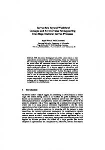
The routing describes the control-flow of the Workflow model. It is a formalised view which is present as a co-ordinated set of process activities (A1, A2, A3, …) that are connected in order to achieve a common goal [1]. WfMC defines parallel routing, sequential routing, AND-split, OR-split, AND-join, OR-join, and iteration as process control elements. Focusing on the formal modelling of the workflow, we can say, that routing varies from case (process instances) to case. In a given workflow model we define by the routing of a case which process activities and in what order they are needed to be carried out. In case of a formal modelling – to be discussed later – there are four basic concepts for routing [4]. Sequential routing – the tasks have to be carried out sequentially, one after the other. Figure 1 depicts sequential routing using the WfMC’s standardised notation.
Figure 1 Sequential routing
331
J. Tick Workflow Model Representation Concept
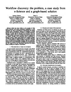
Parallel routing – we refer to parallel routing, when more then one process activities can be carried out at the same time. To execute the parallel routing at the beginning we must use an AND-split to split the control and an AND-join to collect it at the end. The real function of the AND-join is to synchronise the execution (two must wait until both are ready) of the parallel activities, or activity sequences. The real-time parallel execution is rather a possibility than a strict precondition. It means that after A1 is ready, A2 and A3 and A4 could be carried out at the same time, but must not be. The strict condition on A5 to start to execute is that all of the parallel activities (A2 and A3 and A4) must be ready. Figure 2 depicts parallel routing using the WfMC’s standardised notation.
Figure 2 Parallel routing
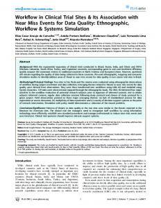
Selective routing – we refer to selective routing, if only one of the process activities have to be carried out at the same time. To execute selective routing at the beginning we must use an OR-split to split the control and an OR-join to collect it at the end. The real function of the OR-join is to choose between the given possible process activities. It means that after A1 is ready, A2 or A3 or A4 could be carried out at the same time. The precondition for A5 to start to execute, is that one of the parallel activities (A2, A3, A4) must be ready. Figure 3 depicts the selective routing using the WfMC’s standardised notation.
Figure 3 Selective routing
332
Magyar Kutatók 7. Nemzetközi Szimpóziuma 7th International Symposium of Hungarian Researchers on Computational Intelligence
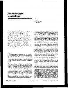
Iterative routing – This routing form defines a workflow activity cycle involving the repetitive execution of one ore more activity(s) until the condition is met. Figure 4 depicts the iterative routing using the WfMC’s standardised notation.
Figure 4 Selective routing
2
Workflow Modelling by Using Unified Modelling Language
Unified Modelling Language is a widespread modelling language in software engineering that is highly standardised and is rich in tools system. Since the control perspective of the Workflow model consists of the description of process activities and their routing per various cases [7], it implies that UML’s sequence diagram and activity diagram will prove to be useful to model the discussed aspects of workflow models. The research work done by W. van der Aalst et al. has resulted in 21 different patterns which describe the behaviour of business processes. [7] S. A. White mapped these patterns from business process model to UML activity diagram. In the following we discuss the four routing methods described above applied to UML. Sequential routing – To map the sequential routing to UML activity diagram is very simple using the elements action state, initial state, final state and control flow. The arrow of the control flow defines the scheduling of the execution. (see Figure 5)
Figure 5 UML activity diagram - Sequential routing
Parallel routing – in the case of parallel routing we use the fork node defined in the activity diagram. The fork node makes it possible to create parallel paths for concurrent action states. It means that there are more active outgoing control flows from the fork node. To synchronise the parallel paths the activity diagram defines the join node which is used at the end of the parallel routing scheme. (see Figure 6)
333
J. Tick Workflow Model Representation Concept
Figure 6 UML activity diagram - Parallel routing
Selective routing – To realise the selective routing we can use the decision node to define alternative paths. The OR-join, which terminates the alternative incoming control flows in the WfMC notation is realised in the UML activity diagram by the merge node. (see Figure 7)
Figure 7 UML activity diagram - Selective routing
Iterative routing – The iterative routing could be seen as a special case of the selective routing and can be built up from the same elements discussed above at selective routing. (see Figure 8)
Figure 8 UML activity diagram - Iterative routing
3
Workflow Modelling using Petri-Nets
The Petri-Net is one of the most important mathematical and graphical representation possibilities of distributed systems, networks and workflows. Introducing Petri-Nets to the field of workflow modelling Aalst and Hee [4] specified a process using Petri-Net as the basic element of workflow. Using the defined process, the four basic routing elements are easy to construct. Sequential routing – In the workflow model the activities have to be carried out one after the other. In the Petri-Net if we link two tasks, we use a place to couple
334
Magyar Kutatók 7. Nemzetközi Szimpóziuma 7th International Symposium of Hungarian Researchers on Computational Intelligence
them together. In the given example (see Figure 9) the task – represented by the transition Task2 – is only performed when the task – represented by the transition Task1 – has been completed. Place C2, where a certain condition is set and must apply, ensures that Task 2 can be carried out if only Task 1 has been completed. [4]
Figure 9 Petri-Net – Sequential routing
Parallel routing – In the workflow model we referred to parallel routing, when more then one process activities can be carried out at the same time. To execute the parallel routing, at the beginning we must use an AND-split to split the control and an AND-join to collect it at the end. In the Petri-Net model we realise ANDsplit by t1 transition, which fires when there is a token in place c1 and generate two tokens, one into c2 and one into c3 places. To synchronise the parallel routes we represent an AND-join by t2 transition, which is deferred until both c4 and c5 places have a token and only then fires and generates one token into the place c6. (see Figure 10)
Figure 10 Petri-Net – Parallel routing
Selective routing – The selective routing includes an OR-split and an OR-join. The OR-split can be realised in two different ways either with possible preconditions or with decision rules [4]. The general solution is the decision rule in t1 transition, which decides which path could be executed next. The general scheme is similar to an AND-split. The OR-join is realised easily with two places and two transitions. (see Figure 11)
335
J. Tick Workflow Model Representation Concept
Figure 11 Petri-Net – Selective routing
Iterative routing – The iterative routing could be modelled by Petri-Net as a special case of the selective routing with an OR-split at the end. Iterating routing can be built up from the same elements discussed above at selective routing. (see Figure 12)
Figure 12 Petri-Net – Iterative routing
Conclusions Each of the presented workflow representation methods has its own place and role in modelling. The UML activity diagram with its richer set of tools provides a more practice oriented approach. Petri-Nets, however, uses a more modest set of graphical tools, therefore its use in visual modelling can become uncomfortable. Its great advantage is that a correct formal mathematical description can be given by its use. Therefore precise, clear and exact proofs can be elaborated purely on mathematical bases.
336
Magyar Kutatók 7. Nemzetközi Szimpóziuma 7th International Symposium of Hungarian Researchers on Computational Intelligence
References [1]
The Workflow Management Coalition Specification, Workflow Management Coalition Terminology & Glossary; Document Number WFMC-TC-1011; Document Status - Issue 3.0; Febr. 1999
[2]
W. M. P. van der Aalst, A. H. M. ter Hofstede: Verification of Workflow Task Structures: A Petri-Net-based Approach
[3]
S. Jablonski, C. Bussler: Workflow Management: Modelling Concepts, Architecture, and Implementation. International Thomson Computer Press, 1996
[4]
W. M. P. van der Aalst, K. M van Hee: Workflow Management – Models, Methods, and Systems, The MIT Press, Cambridge, Massachusetts, London, England, 2002
[5]
S. A. P. White: Process Modelling Notations and Workflow Patterns, [Online] http://www.omg.org /bp-corner/bp-files/Process_Modelling _Notations.pdf
[6]
R. Eshuis, R. Wieringa: Verification Support for Workflow Design with UML Activity Graphs, in the Proceedings of the 24th International Conference on Software Engineering, Orlando, Florida, May 19-25, 2002, pp. 166-176
[7]
P. Hruby: Specification of Workflow Management Systems with UML. In the Proceedings of the 1998 OOPSLA Workshop on Implementation and Application of Object-oriented Workflow Management Systems, Vancouver, BC 1998
[8]
W. M. P. van der Aalst: Three Good Reasons for Using a Petri-Net-based Workflow Management System. In the Proceedings of the International Working Conference on Information and Process Integration in Enterprises (IPIC'96), pp. 179-201, Cambridge, Massachusetts, Nov. 1996
[9]
J. L. Peterson: Petri Net Theory and the Modelling of Systems. Englewood Cliffs: Prentice-Hall, 1981
[10]
A. Pataricza ed.: Formális módszerek az informatikában. Typotex, Budapest, 2006
337