Oct 13, 2006 ... The MicroBlaze Web server design can be downloaded from: www.xilinx.com/
bvdocs/appnotes/xapp433.zip. Application Note: Virtex-4 Family.
Application Note: Virtex-4 Family R
XAPP433 (v2.2) October 13, 2006
Embedded System Example: Web Server Design Using MicroBlaze Soft Processor Authors: Robert Armstrong, Martin Muggli, Matthew Ouellette, and Sathyanarayanan Thammanur
Summary
This application note describes an embedded system example design of a Web server running on the MicroBlaze™ soft processor, designed using the Embedded Development Kit (EDK). The application note also explains how to set up a system as a Web client and how to connect to the Web server running on the MicroBlaze processor.
Hardware Requirements
The following are the hardware requirements for this application note:
Software Requirements
•
Xilinx ML403 Virtex™-4 FX development board. This platform contains the Virtex-4 FX12 FPGA. This design can also be easily re-targeted to the ML401 and ML402 boards by changing the processor target from within the EDK. See “Porting the Design to the ML401 or ML402 Development Boards” for information on porting this design to either of these boards.
•
JTAG Parallel IV Cable or Platform USB Cable.
•
Crossover Ethernet Cable.
•
Crossover or null-modem RS-232 Cable.
The following are the software requirements for this application note: •
Embedded Development Kit (EDK) 8.2i or later.
•
Xilinx Design Tools ISE 8.2i Service Pack 1 (SP1) or later.
•
Internet Explorer, Firefox, or Mozilla Web browser.
•
Web server EDK project (downloaded from the Xilinx Web site). The project can be opened in the Xilinx Platform Studio (XPS), through which the Web server design can be customized and downloaded to the Xilinx FPGA. The MicroBlaze Web server design can be downloaded from: www.xilinx.com/bvdocs/appnotes/xapp433.zip
© 2004, 2006 Xilinx, Inc. All rights reserved. All Xilinx trademarks, registered trademarks, patents, and further disclaimers are as listed at http://www.xilinx.com/legal.htm. All other trademarks and registered trademarks are the property of their respective owners. All specifications are subject to change without notice. NOTICE OF DISCLAIMER: Xilinx is providing this design, code, or information "as is." By providing the design, code, or information as one possible implementation of this feature, application, or standard, Xilinx makes no representation that this implementation is free from any claims of infringement. You are responsible for obtaining any rights you may require for your implementation. Xilinx expressly disclaims any warranty whatsoever with respect to the adequacy of the implementation, including but not limited to any warranties or representations that this implementation is free from claims of infringement and any implied warranties of merchantability or fitness for a particular purpose.
XAPP433 (v2.2) October 13, 2006
www.xilinx.com
1
R
Introduction
Introduction
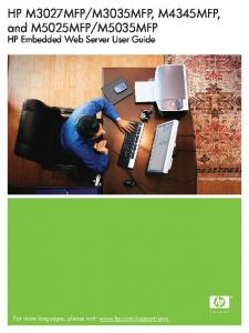
The embedded system design used in this application note contains the following components (see Figure 1): •
A MicroBlaze soft processor connected to 16 Kb of block RAM memory over the On-chip Peripheral Bus (OPB).
•
A UARTLite, an external SRAM memory interface, an Ethernet 10/100 MAC, an external DDR SDRAM memory interface, and a General Purpose I/O (GPIO), all connected to the OPB.
All of the IP cores used in the design are described in the Processor IP Reference Guide included with the EDK. In the design, four GPIO output bits are connected to LEDs (DS4, 5, 6, and 15) on the development board and five input GPIO bits are connected to the directional push buttons. In the design example, the Ethernet MAC is running at 100 Mb/s. To run the example, the peer network connection needs to be set to 100 Mb/s. If the connection auto-negotiates to 1000 Mb/s, the configuration of your PC network adapter needs to be changed to run at 100 Mb/s only. A Fast Simplex Link (FSL) interface provides a fast connection from the OPB MicroBlaze Debug Module (MDM) to the MicroBlaze processor. This download mechanism supports file download speeds up to 500 Kb/s. The xmd.ini file contains the necessary configuration settings that can be used to download files using this interface.
Note: The 10/100 Ethernet MAC OPB peripheral (OPB_ETHERNET) used with this design is available with either a hardware evaluation license or a full license. An evaluation license is included with the EDK, and a full license is available for purchase from Xilinx. The evaluation version of the core includes built-in timeout circuitry that disables the core after a period of time.
XAPP433 (v2.2) October 13, 2006
www.xilinx.com
2
R
Introduction
bram_block lmb_bram
SLMB
PORTB
PORTA
BRAM
BRAM
lmb_bram_if_cntlr ilmb_cntlr
ilmb
dlmb
lmb_bram_if_cntlr dlmb_cntlr
SLMB
PROCESSOR microblaze microblaze_0
0
DLMB
ILMB
DOPB
IOPB
mb_opb SLAVES OF mb_opb 1|0
SOPB
SOPB
opb_ddr DDR_SDRAM_64Mx32
opb_ethernet Ethernet_MAC
opb_gpio LEDs_4Bit
A
B
C
SOPB
SOPB
opb_gpio Push_Buttons_Position
opb_uartlite RS232_Uart
opb_emc SRAM_256Kx32
D
E
F
SOPB
SOPB
opb_mdm debug_module
opb_intc opb_intc_0
0|0
0
SOPB
SOPB
SOPB
2|0
opb_timer opb_timer_1
X433_01_022406
Figure 1: MicroBlaze Web Server Design
XAPP433 (v2.2) October 13, 2006
www.xilinx.com
3
R
Web Server
Table 1 shows the devices used in the Web server design and the memory map for the design.
Table 1: Web Server Design: Devices and Memory Map
IP Core
Version
Memory Address Low
High
Instances
Bus
MicroBlaze Processor
4.00.a
–
–
Microblaze_0
LMB, OPB
OPB MDM
2.00.a
0x41400000
0x4140ffff
debug_module
OPB, FSL
LMB BRAM IF Controller
1.00.b
0x00000000
0x00001fff
dlmb_cntlr, ilmb_cntlr
LMB
OPB UARTLite
1.00.b
0x40600000
0x4060ffff
RS232_Uart
OPB
3.01.b
0x40000000, 0x40020000
0x4000ffff, 0x4002ffff
LEDs_4Bit, Push_Buttons_Position
OPB
OPB DDR
2.00.b
0x28000000
0x2bffffff
DDR_SDRAM_64Mx32
OPB
OPB Ethernet
1.04.a
0x40c00000
0x40c0ffff
Ethernet_MAC
OPB
OPB EMC
2.00.a
0x2c000000
0x2c0fffff
SRAM_256Kx32
OPB
OPB Timer
1.00.b
0x41c00000
0x41c0ffff
opb_timer_1
OPB
OPB GPIO
Web Server
The Web server source code is located in the project’s /WebServer directory. The lwIP and XilMFS libraries accessed by the Web server design are included by the Library Generator (LibGen) utility and have been added to the project via the Software Platform Settings dialog. On this system, the Web server is running HTTP 1.1. A file system, built using the LibXil Memory File System (MFS) library, stores the files for the Web page. The Web page source, including all HTML and images, is located in the project’s /WebPage directory. The server receives requests at port 80. Every request is processed, and replies are sent by the server to the client.
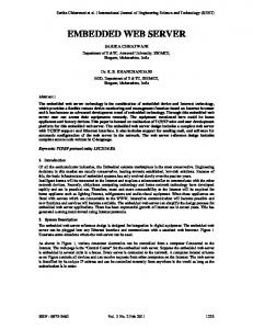
Operations Performed by the Web Server The Web server in the design displays a Web page (see Figure 2) in which the following operations can be performed: •
HEX-digit LED Display When a HEX digit is typed in the Web page, it is displayed as a four-digit binary number on the board’s LEDs when submitted via the Submit button.
•
Image Hosting The Web server can process images in GIF and JPG formats stored in the memory file system.
•
Push Buttons When the board’s directional push buttons are pressed, the binary value is displayed on the Web page when the Web page is reloaded.
•
Host Adobe Acrobat PDF files The Web server can also process PDF files stored within the memory file system.
•
Custom Commands The Web server reference design implements several commands, accessible via the .xwscmd file extension. These commands can be used to view the push button status, change the LED values, etc.
XAPP433 (v2.2) October 13, 2006
www.xilinx.com
4
R
Web Server
Figure 2: Web Page to Control Web Server Operations
Opening the Web Server Design To open the Web server project in the EDK, follow these steps: 1. Unzip the included design files. The design files are the EDK project files describing the Web server. 2. Open XPS by selecting Start → Programs → Xilinx Embedded Development Kit → Xilinx Platform Studio. 3. In XPS, select File → Open Project. The Open Project dialog box appears. 4. Browse to the system.xmp file in the ML403/MicroBlaze directory, and then open the system.xmp file in XPS.
Generating the Netlist and Implementing the Design To generate the system netlist and implement the hardware design, follow these steps: 1. In XPS, generate the netlist by selecting Tools → Generate Netlist. Observe the progress of the operation in the XPS transcript window. The evaluation license for the 10/100 Ethernet MAC Core is used to generate the netlist for that core. 2. Implement the design by selecting Tools → Generate Bitstream in XPS. Observe the progress of the operation in the XPS transcript window. When XPS implements the system, it accesses a UCF constraints file for the ML403 board. The UCF file is located in the supplied /data directory. XPS also uses the OPT option file included in the /etc directory.
XAPP433 (v2.2) October 13, 2006
www.xilinx.com
5
R
Web Server
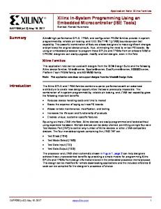
Viewing the Libraries Used in the Design The EDK contains software library support for networking and memory file systems. The Web server design running on the MicroBlaze soft processor uses the lwIP TCP/IP stack, the Xilinx MicroKernel (XMK) operating system, and the XilMFS memory file system library. To view the library settings for the Web server design, follow these steps: 1. In the System tab of the XPS project view window, select Software → Software Platform Settings. 2. In the Software Platform tab of the Software Platform Settings dialog box, observe the Libraries table at the bottom left corner of the dialog box (see Figure 3). The table indicates that the lwIP and XilMFS libraries are used in the design. Also, note that the Xilinx MicroKernel operating system is selected.
Figure 3: Libraries Table in Software Platform Settings Dialog Box
Configuring the Web Server and Compiling the Web Server Code The Web Server reference design requires that a memory file system be initialized for download into the ML403 SRAM before the design can be executed. The MFS image must be generated before the Web Server is downloaded. To generate the MFS image, follow these steps: 1. Open a Cygwin shell from Start → Programs → Xilinx Platform Studio → Accessories → Launch EDK Shell. 2. Change the directory to the project’s /WebPage directory with the "cd" command. 3. Remove any preexisting MFS images in the projects /WebServer directory as follows: rm ../WebServer/*.mfs
XAPP433 (v2.2) October 13, 2006
www.xilinx.com
6
R
Web Server Generate the MFS image as follows: mfsgen –cvbfs ../WebServer/image.mfs 600 404.html index.html logoV2005.gif xapp433.pdf
The command line options and syntax for the "mfsgen" command are listed in the OS and Libraries Document Collection document, in the EDK documentation directory. 4. Exit the EDK shell with the Exit command. 5. In XPS, select Software → Build All User Applications to compile the Web server design.
Downloading the Web Server Code After the Web server code is compiled, the download program must be updated and downloaded to the FPGA. To download the code to the FPGA, follow these steps: 1. In XPS, select Device Configuration → Update Bitstream. In the XPS transcript window, observe that the bitstream is updated by the iMPACT (ISE device configuration) tool.
Note: The iMPACT GUI cannot be open when the Update Bitstream command is running. 2. Connect the JTAG Parallel IV cable or Platform USB cable from the PC to the ML403. 3. In XPS, select Device Configuration → Download Bitstream. The bitstream is downloaded to the development board by the iMPACT tool. When the FPGA device is configured, the DONE light is illuminated on the ML403.
Configuring the Web Client and Running the Web Server Demo 1. Unplug any Ethernet cable connected to the host PC and connect the crossover Ethernet cable to the PC and to the ML403 Ethernet port. The JTAG Parallel IV or Platform USB cable must also remain connected from the PC to the ML403. 2. Modify the host PC’s IP address so it is in the same subnet as the Web server. To change the PC’s IP address, follow these steps: a. Select Start → Settings → Control Panel on the Windows desktop. b.
Double-click Network and Internet Connections.
c.
Right-click the applicable LAN connection, and select Properties.
d. Select Internet Protocol and click Properties.
Note: When the PC’s IP address is changed in the following steps, note the original property settings, so you can reset the original properties after performing the demo. e. In the Internet Protocol Properties dialog box, select Use the following IP Address. f.
In the IP address box, enter a unique IP address in the same subnet as the one you want to use for the Web server. For example, if the IP address you want to use for the Web server is 192.168.1.100, the IP address of 192.168.1.101 can be entered in the IP Address box.
g. Click OK on the Internet Protocol Properties dialog box. h. If a message appears indicating that a subnet mask is missing, select OK again. 3. In XPS, select Debug → Launch XMD. This will allow you to download the MFS image and the Web server application code to the MicroBlaze processor.
Note: The Xilinx Microprocessor Debugger (XMD) is the EDK debug engine for embedded systems. It includes a TCL environment that allows you to create fully customized debug tools. After launching XMD, it sources xmd.ini if the file is present in the EDK project directory. The xmd.ini file contains a list of TCL commands to run each time XMD runs. 4. From XMD, change directory to the project’s /WebServer directory as follows: cd WebServer
XAPP433 (v2.2) October 13, 2006
www.xilinx.com
7
R
Device Utilization and Performance 5. Download the MFS image as follows: dow –data image.mfs 0x2c000000
6. Download the Web server design’s executable code as follows: dow executable.elf
7. Run the application as follows: con
8. Open an HTML browser and point to the http://x.x.x.x URL, where x.x.x.x is the IP address you specified for the Web server.
Note: If the browser uses a proxy to access the Internet, disable the proxy setting and enable a direct connection to the Internet. 9. The Web server demo page should appear in the browser (see Figure 2). Follow the instructions to read the directional push button values and write to the LEDs on the development board.
Porting the Design to the ML401 or ML402 Development Boards To port the Web server design to the Virtex-4 LX and Virtex-4 SX ML402 and ML402 development boards, make the following changes: 1. In Platform Studio, double click on the Project Options header under the Project tab. 2. Change the device to the device on the target development board as follows:
Device Utilization and Performance
♦
For the ML401, change the device to the XC4VLX25-FF668-10C
♦
For the ML402, change the device to the XC4VSX35-FF668-10C
Table 2 provides device utilization and performance metrics.
Table 2: Device Utilization and Performance Metrics Parameters Maximum Frequency (by speed grade)
Device Utilization
Specification/Details XC4VFX12-10
100 MHZ
XC4VFX12-11
110 MHZ
XC4VFX12-12
115 MHZ
Slices
3737
GLCK Buffers
5
RAMB16 (Block RAM)
8
Note: Due to design considerations, although this reference design will meet timing requirements at higher frequencies, it must be operated at 100 MHz.
Reference Design
The MicroBlaze Web server design files can be downloaded from: www.xilinx.com/bvdocs/appnotes/xapp433.zip
XAPP433 (v2.2) October 13, 2006
www.xilinx.com
8
R
Revision History
Revision History
The following table shows the revision history for this document. Date
Version
08/10/04
1.0
Initial Xilinx release in Application Note template.
03/01/06
2.0
Complete Web server redesign and port to EDK 8.1i.
05/05/06
2.1
Added device utilization and performance metrics.
10/13/06
2.2
Updated software requirements to EDK 8.2i or later and ISE 8.2i Service Pack 1 (SP1) or later. In Table 1, changed value for LMB BRAM IF Controller Memory Address High and version number for OPB Ethernet. Additional minor edits.
XAPP433 (v2.2) October 13, 2006
Revision
www.xilinx.com
9