International Conference on Computing, Communication and Automation (ICCCA2015)
Zero Crossing Algorithm Based Phase Recovery for DPLL Based Wireless Communication Sabyasachi Bhattacharyya
Ragib Nasir Ahmed
Department of ECE Institute of Science and Technology, Gauhati University Guwahati, India
[email protected]
Department of ECE School of Technology, Assam Don Bosco University Guwahati, India
[email protected]
Basab Bijoy Purkayastha Department of Physics Indian Institute of Technology Guwahati Guwahati, India
[email protected]
Kaustubh Bhattacharyya Department of ECE School of Technology, Assam Don Bosco University Guwahati, India
[email protected]
Abstract: Recent trends in the field of wireless communication have seen emphasis being given on very high quality reception of signals with minimum error rates. Unlike traditional communication links, which focused on accuracy of received digital intelligence in terms of incorporating efficient coding and decoding techniques, now-a-days, prime importance is given to achieving an accurate estimate of the transmitted passband signal in terms of frequency and phase indirectly leading to good quality bit stream reception. Digital Phase Locked Loops(DPLLs), can optimally perform the above task to regenerate the passband waveform. Zero Crossing (ZC) algorithms are often used to implement DPLLs as they provide a very accurate estimate of parameters such as frequency, phase etc. In this context, our work also focuses on implementing a ZC DPLL based phase recovery system which works optimally with the QPSK modulated signals under faded and noisy channel conditions.
Keywords—zero crossing; phase recovery; fading; synchronization; piece-wise polynomial filter; DPLL loop
demodulation is largely depends upon the accuracy in tracking of the phase and has a direct dependence at higher bit rates where jitter plays a significant role [5]. Zero Crossing (ZC) algorithm can be used as an efficient measure to determine the parameters of a time varying signal such as frequency, phase etc. of the signal [7]. The ZC information of a time varying quantity basically gives a count measure which is directly proportional to parameters such as phase or frequency etc as reported in [7][8][9]. Fading is a very significant phenomenon in wireless transmission because it drastically degrades the performance of any communication system in terms of the signal power received resulting in high bit error at the receiver [5]. The Rayleigh Model is widely used to incorporate the effect of faded channel which considers the wireless channel to consist of N number of Non-Line-of-Sight (NLOS) paths through which the signals propagate to reach the destination, thus giving an accurate estimate of wireless channel [10].
A Phase Locked Loop (PLL) is a feedback system which instantaneously tracks the phase of the incoming signal at the receiver end. It compares the phase of the incoming ‘reference’ signal with the locally generated signal from the oscillatorand adjusts the phase of the local oscillation to match the phases of both the signals.
The design of a ZC based DPLL system for phase recovery of coherently detected signals under the effects of fading and noise is presented in this piece. The DPLL system recovers the instantaneous phase of a QPSK modulated signal corrupted by both fading and channel noise. It has been assumed that there is time synchronization in between the transmitter and the receiver and the receiver has complete knowledge of the starting and ending instants of each symbol or dibit.
Coherent detection techniques which provide a more reliable form of message reception widely used DPLLs. The DPLL provides a base for instantaneous phase tracking of the received passband signal which can be used to retrieve the approximation of the original modulated signal [1]. Once the modulated waveform is regenerated, a direct demodulation could be applied to obtain the original message pulse [2][3]. Some similar approaches have also been discussed in [4][5][6]. It may be noted that in this approach the performance of
In the second section of this piece, a theoretical modeling of the DPLL, the QPSK scheme and Rayleigh Fading has been presented. The third section discusses in detail the Zero Crossing Detection Algorithm and how it is incorporated as a part of the DPLL. In the fourth section, the experimental details, assumptions and specifications have been put forward. The fifth section deals with the proposed working model of the DPLL. The sixth section focuses mainly on the results and related discussions, followed by advantages and limitations of
I. INTRODUCTION
ISBN:978-1-4799-8890-7/15/$31.00 ©2015 IEEE
1273
International Conference on Computing, Communication and Automation (ICCCA2015) the proposed model. In the eighth section, conclusions have been drawn from the overall discussion, followed by future directions which would make the proposed model more efficient.
sin 2 sin where K is the gain of the phase detector. If then
II. THEORETICAL BACKGROUND Most phase tracking systems of now-a-days are designed for detection of instantaneous phase of the time-varying signal or focus on providing a replica of the originally transmitted wave [11].A proper discussion on the components of the DPLL has been laid down in this section. This section also includes brief discussions on the QPSK modulated signals and also on the Rayleigh fading model that has been considered for performance analysis.
sin 2
2.
Loop Filter (LF):The PFD output consists of two terms, one is a high frequency term and the other is a slow changing phase error signal. The useful information is there in the slow changing term, so the loop filter which is low pass filter eliminates the high frequency component and at the output of the filter, we have only the phase error signal [1][12]. The equations (4) and (5) govern the filtering action. Let
denotes the filter output: (4)
e(t) Phase/Frequency Detector (PFD)
(3)
Equation (3) gives the output of the phase detector and it is fed to loop filter.
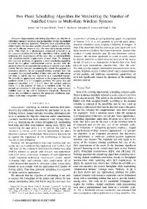
Discrete Domain Model for a Digital Phase Locked Loop: A DPLL essentially comprises of three fundamental components namely, Phase Frequency Detector (PFD), Loop Filter (LF) and Voltage Controlled Oscillator (VCO).It works in a loop to recover the received signal in proper phase and frequency. Figure 1 shows proper block diagram of the DPLL system. Input Reference Signal
sin
1, then approximation of
If
Loop Filter (LF)
is given
by (5)
Equation (5) is the output of the loop filter and it is fed to the VCO.
Voltage Controlled Oscillator (VCO)
ev(t)
3.
Figure 1: Basic Block Diagram of DPLL The theoretical details of each essential component are discussed below: 1.
Phase Frequency Detector (PFD):It compares the phase of the incoming reference signal with that of the locally generated signal of the oscillator to get an estimate of the phase error between the two signals. It is commonly modeled as a digital multiplier which multiplies both the signals and outputs a high frequency term and another slow changing term which gives the phase difference between the two signals [3][4][5]. The action of the PFD can be explained on the basis of the equations (1),(2) and (3).
(6) is the generated frequency, M is an integer where 2 , c is a value and lies in the range 2 is constant value, j is number of bits and the free running frequency.
Let us consider an input signal x(n) such that
QPSK Signal Modeling:
(1) where and are the angular frequency and phase of the input signal respectively. The feedback loop mechanism of DPLL i.e. VCO will generate a sinusoidal signal eVCO(n) given by equation (2) cos
(2)
and are the angular frequency and where phase of the VCO’s generated signal. If the output of the phase detector is denoted by then sin
Voltage Controlled Oscillator (VCO):It is an oscillator which provides an output frequency proportional to the input signal which acts as a control voltage for it [7]. The control voltage as depicted in equation (5) is fed to the VCO and based on that it increases or decreases the frequency of the local oscillator to achieve the ‘phase locking’ of both the signals [5][11]. A generalized equation representing the digitized VCO operation is given by equation (6).
QPSK modulated signals are used in a wide range of applications from voice band modems to high speed satellite communication applications [1]. It provides significant bandwidth conservation through dibit transmission and at the same time maintains a well separated decision boundary resulting in low error rates. In accordance with this discussion, we have also chosen QPSK modulation scheme for testing the performance of the DPLL. The QPSK signal is defined as shown in equation (7). cos 2
cos 0
1274
,
(7) 1,2,3,4
International Conference on Computing, Communication and Automation (ICCCA2015) where, The four available phases are ,
,
,
Rayleigh Fading Channel: We have chosen the Rayleigh Fading Channel Model to test the performance of the proposed DPLL as it provides a realistic estimate of the wireless environment [2]. Let g(t) be the received signal and we assume that there is no LOS path at the receiver end. The signal g(t) can be expressed as given in equation (8) ∑
cos
(8)
where N is the number of paths between the transmitter and the receiver. The phase depends on the varying path lengths and are uniformly distributed over [0,2π]. The Doppler frequency due to the relative motion between the transmitter and the receiver is given by equation (9). cos
(9)
where is the velocity of the mobile user, c is the velocity of light and are uniformly distributed over [0,2π].Equation (8) when subjected to Doppler effect, the received signal s(t) is given by equation (10). ∑
cos
The probability distribution distribution is given by: exp
(10) function
of
Rayleigh
0(11)
III. ZERO CROSSING DETECTION ALGORITHM FOR DPLL Uniformly sampled signals are often processed using its Zero Crossing (ZC) information because of the accurate measures it provides for the signal parameters [2]. From the point of view of wireless communication, this technique is of great significance as it could be used to regenerate the received signals in its originally transmitted phase and frequency thus overcoming the effects of channel degradation. In our proposed model of the DPLL, the PFD utilizes the ZC algorithm to track the difference in phases between the input reference signal and locally generated oscillation provided that the frequencies are matched coherently.Phase Modulated systems do not undergo much variation in frequency, so coherent matching is acceptable [12]. Analytical Modeling of Zero Crossing DPLL Algorithms: The PFD of the DPLL performs the phase matching operation symbol wise i.e. for each dibit duration or one symbol duration at a time using ZC algorithms. There are many important conclusions from the ZC algorithms. An important conclusion which is very significant for our proposed model of the DPLL is discussed below: Instantaneous Phase matching: It aims at transforming the VCO’s free running oscillation into a signal which is matched
in terms of both frequency and phase to the incoming reference signal. Such a signal which is matched in both frequency and phase to the incoming signal will obviously be free from distortion as it is locally generated and thus it will represent a non-degraded version of the incoming reference signal which is nothing but an approximation of the originally transmitted QPSK signal. Such a signal can be put through a direct demodulation to obtain the transmitted message bits at the receiver end. To achieve this, the ZC conclusion related to phase is used which says the first positive to negative zero crossing for any periodic sequence or signal gives a measure of the phase of the signal called as the ‘phase count’. The instantaneous phase of the signal or symbol is directly proportional to this phase count [1][2][3][12].Two phase counts are obtained, firstly the count for a particular symbol of the input reference signal is calculated which is given by . Another phase count is measured for the locally say generated VCO’s oscillation which is denoted by . The difference between the phase counts of the input reference symbol and the local oscillator’s signal is calculated as shown in equation (12). (12) The magnitude of the ‘difference count’ determines by how much the phases of both the signals vary and its sign represents the whether the VCO’s signal lags or leads the particular symbol in phase. Based on the magnitude and sign of the difference count, the VCO signal’s samples are circularly shifted either clock wise or anti clockwise to achieve the phase matching between the two signals using a circular left/right shift algorithm. Thus, at the end of this process, we obtain an approximated version of the originally transmitted QPSK signal. A similar approach has also been taken up in the works done under [1][2][3][12]. For clear understanding of the phase matching algorithm, let us take up the samples for an arbitrary symbol and apply the algorithm to it. Let us denote the samples of the incoming symbol by and the samples of the VCO’s signal by such that both are of length ‘10’ and have values: 1.85 1.67 0.86 0.53 0.76 1.23 1.46 1.85 1.31 0.20 1.34 1.23 1.06 0.85 0.38 0.68 0.97 1.04 1.14 0.95 When observed carefully, the phase count i.e. the first positive to negative zero crossing occurs for incoming symbol, at position or index equal to ‘4’. But for the VCO samples, the first zero crossing occurs at position or index equal to ‘5’. Therefore, the difference between the phases is calculated as:5 1 From the above calculation the difference of phase count is obtained as ‘-1’. It means that VCO signal should be
1275
4
International Conference on Computing, Communication and Automation (ICCCA2015) circularly shifted by ‘1’ position or index and the shift should be a right shift or in clock-wise direction. After application of the shift algorithm, the new arrangement of the samples of the VCO signal is shown below: 1.23 1.06 0.85 0.38 0.68 0.97 1.04 1.14 0.95 1.34 and , we see that Now, on observing both the signals have the same phase count and thus the resulting VCO signal is matched in phase with the received input symbol. In terms of the DPLL, this matching of the phase count of both the signals corresponds to the phase locked state of a DPLL [12]. Similar works can be found in [1][2][5][7]. IV. EXPERIMENTAL DETAILS At a very initial stage after designing of the ZC DPLL system, it is tested with some test signals before it is applied to the realistic communication link. A constant frequency, constant phase sinusoid is generated and then it is corrupted by adding AWGN noise at 3dB to achieve just sufficient signal degradation for a test scenario. This degraded test signal is applied to the proposed receiver device. Each component of the proposed device i.e. the Piece-Wise Polynomial Filter (PPF), the Phase Frequency Detector (PFD), the Loop Filter (LF) and the Digitally Controlled Oscillator (DCO) are tested under this degraded signal. The output of each component is observed. This gives us an estimate about the performance of the proposed DPLL under limited signal degradation. After this initial testing phase, the ZC DPLL is tested under the complete communication link. A detailed discussion on the various processes carried out in the communication link with the proper specifications and parameters has been presented below. A random binary bit stream of 30,000 bits is generated at the transmitter end. We are mainly focused on M-ary transmission, so the generated bit stream is paired up into dibit combination for such transmission. After that the binary coded baseband symbols are generated for each dibit. These binary coded symbols are converted to gray coded symbols for achieving minimum distance between subsequent symbols, for optimum performance of the system. Now, after the proper baseband symbols are achieved, they are baseband modulated (complex envelope) using the QPSK modulated signals which give four different phase shifts for the four possible baseband symbols. A carrier of 900 MHz frequency is used for transmission. Thus, the passband QPSK modulated signal is transmitted through the realistic wireless channel. The fading channel chosen for analysis of the DPLL performance is the Rayleigh Channel. The random envelope of the Rayleigh faded channel is obtained from the complex Rayleigh variable and it is product multiplied with the QPSK samples resulting in degradation or fading of the transmitted signal. Besides the fading model, another degradation factor that has been modeled is the random channel noise. The channel noise is modeled using the popular Additive White Gaussian Noise (AWGN) model and the DPLL performance is evaluated over
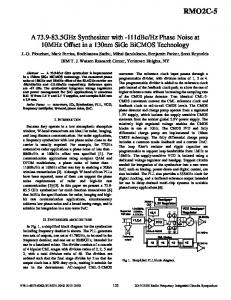
noise levels corresponding to a Signal-to-Noise Ratio in the range from -10dB to 10dB. The Rayleigh faded signal corrupted by AWGN channel noise is received at the receiver input. A Piece Wise Polynomial Filter (PPF) which is implemented using a 6thorders Savitsky-Golay Filter as mentioned described in [12] is used to achieve a minimum degradation signal which is fed to the input of the DPLL. The Phase Frequency Detector (PFD) is modeled as a digital multiplier. Also, in our experiment we have evaluated a difference of the phase count of the two signals by individually estimating the phase counts for each symbol and also that of the VCO’s oscillation using ZC information. This difference count is fed as a parameter instead of the error signal so as to make the job simpler. The Loop Filter(LF) is implemented as a simple non-recursive FIR filter which acts as an averaging filter. The VCO is implemented in our case as a Digitally Controlled Oscillator (DCO). Thus, the DPLL model locks the phases of both signals and the DCO’s output signal is an approximation of the originally transmitted QPSK modulated wave which is our desired passband signal of interest. This recovered modulated signal is fed to a direct demodulation block consisting of a standard QPSK demodulator. A complex envelope is formed with the real term given by the in phase sum and imaginary part given by the quadrature phase sum. This complex envelope replicates originally baseband modulated QPSK envelope which is subjected to the reverse processes of those applied at the transmitter to obtain the received bit stream. We, however, intend to observe the performance of the DPLL as a standalone device and therefore have not modeled any standard channel coding technique. Finally, the transmitted bits and received bits are compared under a BER calculation block which is used for performance analysis of the DPLL reception. The bit error rate BER is calculated at different values of SNR in the specified range of -10 to 10 dB. V. WORKING MODEL OF PHASE RECOVERY FOR ZC- DPLL The proposed DPLL system is designed for recovery of the transmitted passband signal in its original phase provided that the frequency is coherently matched. The ZC DPLL model consists of basically four major components namely, Piece wise Polynomial Filter (PPF), Phase Frequency Detector (PFD), Loop Filter (LF) and the Digitally Controlled Oscillator (DCO). The block diagram for the proposed model is shown in figure 2.The DPLL performs the operations for uniformly sampled signals and tracks the phase for moderately sampled signals in general. However, very low sampling rates are not desirable as the system’s core is formed by ZC algorithms for which it is necessary to have sufficiently large number of samples to achieve the desired performance[1][2][3]. The phase tracking performance of the model, is, in fact a direct function of the sampling rate. This, therefore, also accounts for a trade off in terms of bandwidth requirement of the system. The DPLL performs the whole operation in a piece wise manner, which is facilitated by the
1276
International Conference on Computing, Communication and Automation (ICCCA2015) PPF filter block i.e. the signal is processed one symbol at a time. Input Reference Signal t=iTs Symbol-wise Operation
Original message bit stream
Piece-wise Polynomial Filter (PPF)
Phase Frequency Detector (PFD)
Loop Filter (LF) Message Reconstructed Signal
Digitally Controlled Oscillator (DCO)
QPSK Demodulation
Phase Count
Phase Matched Signal
DPLL Loop
Figure 2: Block Diagram of the Working Model The processing or action of each of the components of the DPLL is explained below: Piece-Wise Polynomial Fitting Filter (PPF): The Piece-Wise Polynomial Filter (PPF) is not an integral part of any traditional design approach for DPLL systems. But for the design of such systems based on higher order algorithms or for that matter techniques involving very vital information about a signal such as zero crossing rate, peak duration etc., the PPF becomes an essential part of the DPLL system. The PPF regenerates a signal with minimum distortion from which the zero crossing information can be accurately determined. The PPF for our proposed model has been implemented using a sixth order polynomial fitting equation which was proposed by Savitzky and Golay in a research paper around 22 years ago [12]. The generalized mathematical model proposed by the two researchers has been discussed below:According to the two researchers, the numerical values of 2 1data points can be approximated and equally spaced along the abscissa, as a polynomial degree of n where 2 1. ∑ (13) The derivative of the polynomial are given by equation (14), (15) and (16) 2 (14) 2
1
(15)
! (16) Phase Frequency Detector (PFD):The second and one of the most significant components of the proposed DPLL is the Phase Frequency Detector (PFD). The PFD basically tracks the instantaneous phase of the signal. The PFD basically does two operations; firstly it generates the phase error signal between the input reference signal and the free running oscillation of the signal and it uses the conclusions of zero crossing techniques to evaluate a ‘difference count’ which is nothing but the difference of the phase counts of the input reference symbol and the DCO’s oscillation. The PFD performs the first task in which it tracks the phase error signal by acting as a digital multiplier which can be described using the equations(1), (2), (3).
In addition, the PFD now evaluates the difference in the phase count of both the signals as described by equation (12). The phase error signal is fed to the loop filter and the is fed to the DCO for further differencecount processing. Loop Filter (LF):Our proposed model of the DPLL incorporates the loop filter using a non-recursive finite impulse response (FIR) filter which eliminates the high frequency terms that exist due to trigonometric expansions [1]. The input samples are weighted according to the direct coefficients of the FIR filter which are determined using inverse Fourier Transform. The above discussion can be mathematically analyzed using the equations (17). ∑ (17) Digitally Controlled Oscillator (DCO): The Digitally Controlled Oscillator (DCO) is the most significant block of our proposed model as it performs the crucial operation of phase matching. The DCO that we have modeled takes the difference count from the PFD as its input. This difference count consists of a magnitude and a sign part.The DCO utilizes these two information and rearranges the samples of the free running signal using a circular left/right shift algorithm so that after the DCO operation both the signals have the same phase count. The rearranged DCO signal represents an approximation of the transmitted QPSK signal which can be directly demodulated to get the originally transmitted message sequence [3]. The above operation of the proposed DCO can be elaborated on the basis of the equation (6). VI. RESULTS AND DISCUSSIONS The DPLL system was tested under the wireless communication link by transmitting a random stream of30,000 bits through the link and receiving those 30,000 bits at the receiver end with a certain error rate at particular power level. The simulation was carried out for a total time equal to 1 second. The total simulation time was taken as 1 second and the output waveforms are plotted in a time scale of 0 to 0.2 seconds. Vivid descriptions of the practical results obtained from the simulation are elaborated below. Figure 3 depicts the QPSK modulated wave at the transmitter end, the transmitted wave under Rayleigh Fading effect and also the corrupted signal under the combined effect of Rayleigh Fading.
1277
International Conference on Computing, Communication and Automation (ICCCA2015) Figure 3: Waveforms for QPSK Modulated Signal, Rayleigh Faded Signal and Corrupted Signal under the combined effect of both Rayleigh Fading and AWGN Noise. The corrupted received signal, the PPF filtered output and the free running Oscillation of the DCO are shown in figure 4. Figure 7: Comparison between the originally transmitted message pulse and the regenerated message pulse Table 1 shows a comparative study of the BER levels for an SNR range from -10 to 10dB. The comparison is shown between the proposed DPLL based system and the traditional theoretical QPSK system. Table 1: Comparative study of error rates of proposed DPLL system and traditional QPSK system
Figure 4: Waveforms for the received corrupted signal, PPF Filter output and free running oscillation of DCO Figure 5 illustrates the outputs for different components of the DPLL, i.e. the output of the PFD, that of the LF and also that of the DCO.
SL. No.
SNR in dB (Eb/N0)
1. 2. 3. 4. 5 6 7 8 9 10 11
-10 -8 -6 -4 -2 0 2 4 6 8 10
Bit Error Rate (BER) Theoretical QPSK System
Proposed DPLL Based System
0.3492 0.3151 0.2760 0.2332 0.1890 0.1465 0.1085 0.0771 0.0530 0.0355 0.0233
0.3020 0.2579 0.2125 0.1689 0.1273 0.0910 0.0592 0.0409 0.0261 0.0199 0.0153
Figure 8 illustrates a comparative plot of the BER vs. SNR curves that have been plotted for both the systems. Figure 5: Waveforms for Phase-Frequency Detector’s Output, Loop Filter’s Output and DCO’s output Figure 6 depicts a comparison of the original QPSK signal and the reconstructed wave at the DCO output.
Figure 8: Comparative study of BER vs. SNR plots for proposed ZC DPLL and theoretical QPSK system
Figure 6: Comparison between the originally transmitted QPSK signal and the reconstructed waveform Figure 7 compares the originally transmitted message pulse with the regenerated message pulse after demodulation.
After reception of the acutely degraded passband time varying signal from the wireless chanel, the PFF provides a minimum degradation signal from the corrupted received signal. The different waveforms have been shown in figures 3 and 4. The ZC DPLL corrects the phase of the frequency matched local oscillator DCO signal with respect to that of the PPF output. The PFD generates the phase error signal consisting of a high frequency component which is eliminated by the LF to get a slow changing signal of containing the phase difference between the two signals. According to the phase difference
1278
International Conference on Computing, Communication and Automation (ICCCA2015) information, the DCO corrects the phase of the free running signal to match the phases of the both the signals such that an approximation of the originally transmitted QPSK wave is regenerated at the DCO output. The action of the different components of the DPLL has been elaborated using the figures 5 and 6. By demodulating the DCO output, the transmitted bits are extracted with a certain error rate within a particular SNR range. This regeneration of the bits is illustrated using figure 8. Based on Table 1 and figure 8, it can be stated that within the given range of SNR, the proposed DPLL system shows a comparatively enhanced error performance than that of the standard QPSK system.
ACKNOWLEDGMENT We are highly grateful to Mrs. Aradhana Misra, Assistant Professor, Dept. of ECE, Institute of Science and Technology, Gauhati University (GUIST) for her constant help and valuable inputs in shaping the proposed work in a proper direction. We are also highly thankful to all the other faculty members, teaching and non-teaching staff at Dept. of ECE, GUIST and Dept. of ECE, DBCET for all their help and support. Last but not the least, we would like to thank all our friends at GUIST and DBCET for the consistent help and support which motivated us to propose the work in a proper manner.
VII. ADVANTAGES AND LIMITATIONS
REFERENCES [1]
Advantages: •
•
•
The proposed DPLL has better error performance as compared to traditional communication systems in the specified SNR range. The need for the loop filter is eliminated here as the DCO’s phase locked can be directly demodulated to get the received message stream. The requirement of storage components or memory is lessened as we need to deal with only a count from the PFD instead of the entire phase error signal.
Limitations: One possible limitation or demerit of the proposed system might be in terms of its bandwidth requirement.The phase tracking process of the system is ZC based and thus it is a direct function of the applied sampling frequency, which leads to higher bandwidth requirement. VIII. CONCLUSION The proposed ZCDPLL recovers the QPSK waveform with optimum error of tracking and finally the demodulated bit stream is obtained at error rates less than that of the standard QPSK system under a specified range of SNR. Thus the ZC DPLL proposed emerges as a powerful means to retrieve digital intelligence over noisy and faded wireless channels with enhanced error performance It, therefore, forms a base for implementation of phase tracking devices for recovery of digital information under degraded wireless environments at low error rates. IX. FUTURE DIRECTION Multiple signal communication i.e. MIMO systems are widely implemented in today’s time. MIMO technology makes use of Quadrature Amplitude Modulation (QAM) which being a hybrid scheme, extra care needs to be taken for its reception and demodulation. The proposed DPLL, having emerged as a powerful tool for good quality reception can be considered for phase tracking in a MIMO system to achieve improved error performance for such higher level systems.
Basab B Purkayastha and Kandarpa Kumar Sarma, “A Digital Phase Locked Loop based System for Nagakami-m fading Channel Mode”, International Journal of Computer Applications (0975-8887), Volume 42, No. 9, March 2012, pp. 1-8 [2] Ahmed Telba, “Low Jitter Circuits in Digital System using Phase Locked Loop”, in the Proceedings of the World Congress of Engineering 2013 Vol II, WCE 2013, ISBN No. 978-988-19252-8-2, London, U.K. , July 3-5, 2013, pp. 1-6. [3] Basab B Purkayastha and Kandarpa Kumar Sarma, “Digital Phase Locked Loop Based Carrier Recovery System for Rayleigh and Rician Channels”, IRNET Transactions on Electrical and Electronics Engineering (ITEEE), Vol 1, Issue 2, ISSN 2319-2577, 2012. [4] Qassim Nasir and Saleh Al-Araji, “Linearized Phase Detector Zero Crossing DPLL Performance Evaluation in Faded Mobile Channels”, Circits and Systems, Journal of Scintific Research, doi:10.4236/cs.2011.23021, July 2011, pp. 139-144. [5] Patrik G. Ogmundson and Peter F. Driessen, “Zero Crossing DPLL Bit Synchronizer with Pattern Jitter Comensation”, IEEE Transactions on Communications, Vol. 39, No. 4, April 1991, pp. 603-609. [6] Qassim Nasir, “Extended Lock Range Zero-Crossing Digital PhaseLocked Loop with Time Delay”, EURASIP Journal Wireless Communication and Networking, 2005, pp. 413-418. [7] R.W. Wall, ”Simple Methods for Detecting Zero Crossing”, in the Proceedings of IECON’03, Industrial Electronics Society the 29th Annual Conference of the IEEE, ISBN No. 0-7803-7906-3, November 2003, pp. 2-5. [8] B.-U. Kohler, C. Hennig and R. Orglmeister, “QRS Detection Using Zero Crossing Counts”, Progress in Biomedical Research, Vol. 8 No. 3, September 2003, pp.138-144. [9] Fu Zhang, Murali Yeddanapudi and Pieter J. Mosterman, “ZeroCrossing Location and Detection Algorithms for Hybrid System Simulation”, The MathWorks, Inc., Natick, MA 01760, USA, pp. 1-5. [10] Pieter F. Driessen, “DPLL Bit Synchronizer with Rapid Acquisition Using Adaptive Kalman Filtering Techniques”, IEEE Transactions on Communications, Vol. 42, No. 9, September 1994, pp. 2673-2675. [11] Sabyasachi Bhattacharyya, Ragib Nasir Ahmed, Ripunjoy Sarma, Roushan Saikia and Kaustubh Bhattacharyya, “MUX-Based Design of DPLL for Wireless Communication”, in the Proceedings of fourth International Conference on Information Communication & Embedded Systems 2014 (ICICES2014), S.A. Engineering College, Chennai, Tamil Nadu, India, ISBN No. 978-1-4799-3834-6, IEEE, 2014, pp. 1-5. [12] Basab Bijoy Purkayastha and Dr. Kandarpa Kumar Sarma, “A Digital Phase-Locked Loop based Signal and Symbol Recovery System for Wireless Channel”, M.Tech Thesis submitted in the Department of Electronics and Communication Technology, Institute of Science and Technology, Gauhati University, June 2012.
1279