purpose HW and open source SW (e.g., Linux and FreeBSD) recently ... above all others â and applications offer an ever growing support to ... and monitoring.
1
DROP: An Open-Source Project towards Distributed SW Router Architectures Raffaele Bolla, Member, IEEE, Roberto Bruschi, Guerino Lamanna and Andrea Ranieri Department of Communications, Computer and Systems Science (DIST) University of Genoa Via Opera Pia 13, 16145 Genova, Italy phone: +39 010 353 2075; fax: +39 010 353 2154 e-mail: {raffaele.bolla, roberto.bruschi, guerino.lamanna, andrea.ranieri}@unige.it
Abstract— In this work, our main objective is to explore how Software Routers (SRs) can deploy advanced and flexible paradigms for supporting novel control plane functionalities and applications. To this purpose, we explore and study a new opensource SW framework, namely Distributed SW ROuter Project (DROP), which aims at developing and enabling a novel distributed paradigm for IP-router control and management. DROP is partially based on the main guidelines of the IETF ForCES standard (and can be also considered as its sole opensource realization), and it allows building logical network nodes through the aggregation of multiple SRs, which can be devoted to packet forwarding or to control operations. In addition to the original ForCES design, DROP will aim at extending router distribution and aggregation concepts by moving them at a geographical/network-wise scale in order to enable and to support value-added services for next-generation networks. Index Terms—SW Router, ForCES, distributed router architecture, open source SW.
I. INTRODUCTION
T
HE evolution of IP-router and IP-network architectures are two of the most important aspects of the Internet as we know it today. The users’ demand of novel and more complex services, as well as significant constraints imposed by current technologies, makes the design of next-generation IP-routers hard and challenging. Next-generation router architectures are expected to provide “classical” capabilities, such as availability, reliability, modularity and performance scalability, as well as the support of novel functionalities and features, which spans from energy-efficiency requirements to advanced levels of flexibility and programmability. These last ones are heavily required to lead network equipment following and supporting the evolution of the next-generation Internet, where novel value-added services will work through specific applicative overlays on the top of the IP layer. Thus, future network nodes are supposed to flexibly include novel multi-layer functionalities at both control and data planes, by allowing to map and to effectively interface them towards the network layer capabilities (e.g., QoS, reliability, multicast, etc.). In such a scenario, router architectures based on general purpose HW and open source SW (e.g., Linux and FreeBSD) recently regained a remarkable consideration from the industrial and academic communities.
Such renewed interest certainly springs from the intrinsic nature of new-generation Software Router platforms, which provides complex mixtures of flexible SW-based commodities and efficient HW-based offload functionalities, with a boundary continuously changing over time. HW capabilities can expose flexible header processing APIs, and software functionalities can rely on offload HW. Increasing numbers of network HW features are becoming “programmable” and most commodity CPU designs are dedicating HW blocks to optimize special categories of instructions ranging from multimedia through encryption. CPUs are being designed in close association with NICs to enable a virtualized I/O processing. Software bridges are becoming more sophisticated in Virtual Machines running on commodity CPUs and it is not hard to guess that their capabilities may end up running in special cores. Effectively, networks-in-the-small are already apparent within modern servers, and SR can effectively exploit these low level networks to realize higher-level ones. At the same time, open-source operating systems – Linux above all others – and applications offer an ever growing support to such HW enhancements, and consistently include the large part of the state-of-the-art networking capabilities and functionalities. Recent works, like [1] and [2], show and analyze new generation SR platforms, able to exploit a Linux-based networking SW system and to correctly deploy a multiCPU/core PC architecture. In more detail, these works show how this kind of platforms can scalably achieve a remarkable level of data plane performance, while at the same time preserving portions of the PC computational power for the application layer. Starting from these considerations, we want take a step forward towards the SRs’ evolution, by moving the focus away from their data plane performance analysis, useful to demonstrate their feasibility and viability with respect to commercial HW platforms. In this work, our main objective is to explore how SRs can deploy advanced and flexible paradigms for supporting novel control plane functionalities and applications. To this purpose, we explore and study a new open-source SW framework, namely Distributed SW ROuter Project (DROP) [3], which aims at developing and enabling a novel distributed paradigm for IP-router control and management.
2
II. STANDARD LINUX SW ROUTER ARCHITECTURES Standard architectures for monolithic SR have to provide a wide and heterogeneous set of functionalities and capabilities: from the ones directly involved in the packet forwarding/switching process to the ones needed for control functionalities (e.g, OSPF, BGP, etc.), dynamic configuration and monitoring. Focusing on Linux based architectures, as outlined in [10], [11] and [12], all the forwarding functions are realized inside the Linux kernel, while the large part of the control and monitoring operations (the signaling protocols like, for example, routing protocols, control protocols, etc.) are daemons/applications running in user mode. The most wellknown examples of network applications/daemons are the Quagga [16] and the XORP [13] routing suites.
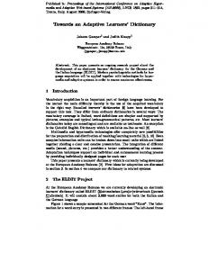
Thus, similarly to their commercial cousins, SRs obviously provide two main kinds of internal traffic paths, namely the “fast” and the “slow” paths, respectively. The fast path substantially consists in the L2 and L3 forwarding chain, and it is selected for all data packets that need only to be routed or switched, and which do not require elaboration at service/control layer of the local router. On the contrary, the slow path is used by all packets that are directed towards local service and control applications (e.g., OSPF Hellos and LSUs, as well as BGP keep-alives have to be delivered to local IP control applications). Packets following the slow path are generally referred as “exception” packets. As pointed out in Fig. 1, the delivery of exception packets to control and service applications is performed through wellknown standard interfaces between kernel and user spaces, namely network sockets. Control and Service Layer
Router Control L2 Control L3 Control Plane (Quagga) Services & quagga Plane Plane Applications & Services
User space
Control Status API
Packet Sockets
L3 FIB L3 forwarding Chain
PHY
Kernel space
PHY
In more detail, DROP is partially based on the IETF ForCES [14] architecture (and can be also considered as the sole open-source realization of this standard), and it allows building logical network nodes through the aggregation of multiple devices (i.e., SRs), which can be devoted to packet forwarding or to control operations. As suggested by the IETF ForCES directives, DROP provides an internal architectural solution able to hide the complexity of distributed network nodes in an autonomic way, and offers a single control and management interface to users. Moreover, in addition to the ForCES guidelines and related prototypic developments [6], DROP will aim in the next future at extending router distribution and aggregation concepts by moving them at a geographical/network-wise scale. In this respect, the basic idea consists in enabling a selected set of network edge devices, or part of them (i.e., one or more network interfaces), to coordinately work like a single logical node with a sole configuration and management interface. This will allow network operators creating and developing novel and more flexible frameworks for supporting and managing novel value-added services. For example, let us consider the case of the classical provider-based VPN service. Through the adoption of the DROP framework, edge interfaces towards customer sites can be aggregated together in a single logical node, whose management and configuration interface can be given at customer disposal in order to self-configure a set of advanced and value-added functionalities and applicative requirements, and to directly map them in edge devices. In this sense, DROP can be considered as strategic means for disruptively boosting the development of next-generation user- and service-centric network functionalities. This paper is organized as in the following. The next section briefly introduces Linux SR architectures by focusing on the internal APIs used between its control and data planes. Section III provides an overview on the DROP architecture and its functional design. Section IV describes in detail the main building blocks of the proposed framework, and the protocols used for intercommunication among elements. Section V reports the test results performed to analyze the performance and the architectural bottlenecks of the DROP prototype. Finally, the conclusions are summarized in Section VI.
L2 FIB L2 forwarding Chain
Switching Matrix Figure 1. Reference architetecture of a Linux based monolithic SR.
Besides the packet related API, a router architecture needs a further set of interfaces between data and control planes in order to exchange control data (e.g., for updating Forwarding Information dataBase (FIB), or for exchanging information about the status of a network interface). In this regard, Linux includes a highly advanced and complete API, namely Netlink [15], which is used as an intrakernel messaging system as well as between kernel and user spaces. Netlink includes all the L2 and L3 interfacing capabilities, needed to synchronize the control and the data engines of an entire router. Netlink also allows bidirectional unicast, multicast and broadcast delivery of control data between data plane components and control plane applications. III. OVERVIEW OF THE DROP ARCHITECTURE As shown in Fig. 1, a distributed router architecture can be substantially thought as the aggregation of a certain number of router elements, each one exposing a set “public” network interfaces (i.e., the real interfaces of the “aggregated router”)
3 towards the external word. In order to provide the connectivity among the router components, each element has also to provide one or more interfaces towards a backplane (or “internal”) network. The intrinsic nature of such kind of architectures obviously leads to different issues in distributing, re-designing and synchronizing the large part of the router functionalities. As previously sketched, our approach tries to face and to address such designing issues by focusing on Linux PC-based SR platforms, which are widely and detailed introduced in [10]. In order to go beyond the standard monolithic SR architecture, and to effectively aggregate the data plane capabilities of multiple SRs by providing a sole and distributed control plane, we decided to •
use, as much as possible, SR and Linux based resources, mechanisms and protocols (e.g., Netlink, Quagga, etc.)
•
base the DROP prototypic architecture on the main guidelines of the IETF ForCES standard.
Figure 2. An example of distributed router architecture.
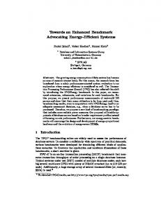
While [8] reports the complete architecture suggested by the ForCES standard, DROP can be considered, from a certain point of view, as a simple proof-of-concept prototype that includes the following main building blocks: • Control Elements (CE): SRs dedicated to control functionalities, and able to take management and routing decisions through the Quagga routing suite [16]; • Forwarding Elements (FE): SRs devoted to data plane operations, which are specifically tailored and tuned to efficiently perform the IP forwarding process; • An Internal/Private Network (IPN): a network connecting all the control and forwarding elements. This network is fully devoted to internal connectivity of the distributed router, and cannot be reached by “external” hosts. At the current development stage of the DROP framework, the IPN consists in a simple Ethernet network, but, in the next future, it will be replaced by an overlay network, where the connectivity between two router elements will be realized through GRE tunnels. In more detail, the usage an overlay network, partially
derived from state-of-the-art peer-to-peer technologies, will allow to natively redistribute control data and advanced intelligence among DROP elements, allowing devices to independently and adaptively auto-reconfigure themselves according to network and service-specific requirements. Such distributed paradigms will be the key element in order to achieve the service convergence inside multi-layer programmable nodes, and to allow the DROP architecture scaling towards geographical/network-wise deployments. In order to realize a basic set of ForCES functionalities, as shown in Fig. 2, we developed two main SW applications, namely Forwarding and Control Element Controllers (FEC and CEC) respectively. These applications may be thought as a sort of middleware between the distributed data plane of FEs and the control plane functionalities running on the CE. The main objective of this middleware is obviously to smartly manage control and data planes interactions, by allowing the distribution of IP routing functionalities in an effective and autonomic way. With this aim, CECs are devoted to manage and exchange information concerning the whole aggregated router with the control applications (e.g., Quagga), while FECs are locally responsible for managing forwarding configuration (local FIB, local interfaces’ configuration and status) of each FE. In detail, while CECs provide to control plane application the full database of the distributed router, FECs must work with the local data plane by using only a data subset corresponding to local router resources. The disaggregation of such information is centrally guided in an autonomic way by the CECs, which are responsible for separately “deriving” from the “aggregated RIB” all the routing information and configurations for each FE. Regarding the FECs, they are devoted both to apply CECs’ commands and configurations, and to forward to CECs all routing exception data. This includes on one hand the forwarding of internal control messages (e.g., media up/down of a network interface), and, on the other hand, the redirection of routing packets (e.g., OSPF packets) received the local interfaces to the CE, and vice and versa. Moreover, CEC and FEC applications are jointly responsible for the dynamically join and leave of router elements (both CE and FE). All the CEC-FEC bidirectional interactions and communications are provided through the ForCES protocol, and, in detail, the control data configuration messages are realized with the Netlink sintax. Regarding the FE and CE internal APIs, standard Linux packet and Netlink sockets are used. The control plane application that we adopted for realizing the proposed prototype is Quagga [16], because of our previous experience with this software and its ease of modification. In order to interface this SW routing suite towards the CEC, we produced two simple SW patches for Zebra and OSPFd routing daemons. The purpose of the modifications applied to these daemons was to re-direct towards our Netlink Server the communication between such daemons and the data plane.
4
CE 1
CE 2 Router Control Plane (Quagga)
Router Control Plane (Quagga)
CEC
CEC
FE 1
FE 2
FE N
FEC Packet Sockets
FEC Control API
Packet Sockets
FEC Control API
Packet Sockets
Control API
L3 FIB
L3 FIB
L3 FIB
L2 FIB
L2 FIB
L2 FIB
Figure 3. Proposed distributed SW router architecture.
IV. SW BUILDING BLOCKS AND STANDARD INTERFACES As previously outlined, the DROP architectures is substantially composed by two main applications, and by a set of “standard” interfaces to deliver “slow path packets” and control data. In the following of this section, we describe in detail: i) the Netlink protocol, which has a double usage: a. to deliver control data among DROP elements; b. to deliver control data between user and kernel space of the same element; ii) the FEC application; iii) the CEC application. A. The Netlink protocol The focus of this sub-section is to describe Netlink functionalities as a protocol between a FEC and a CEC, the two components that define a generic distributed router. Thus, this sub-section ignores other uses of Netlink, including its use as a intra-kernel messaging system, as an inter-process communication procedure, or as a configuration tool for other non-networking or non-IP network services. Netlink logically models FECs and CECs in the form of nodes interconnected to each other via a shared medium. The medium is implementation-specific (a dedicated bus of a switch fabric backplane, a Gigabit Ethernet, etc.). Nodes (CPCs or FECs) connect to the medium and register to receive specific messages of interest for processing or just monitoring purposes. CPCs may connect to multiple wires if it helps them to better control the service. All nodes dump packets on the shared medium, but packets can be discarded by the wire if they are malformed or not specifically formatted for the wire.
Dropped packets are not seen by any of the nodes, although, if Netlink detects a malformed packet, the service may signal an error to the sender. In our specific implementation, the Netlink protocol is used for kernel space to user space communication and for internal control-plane communication only. We chose to rely on ForCES protocol in order to provide control-plane to forwarding-plane communication services. B. Forwarding Element Controller The collection of ForCES-specific software applications running on each FE takes the name of Forwarding Element Controller (FEC). FECs are control applications that act mainly as a SW bridge between the Control Element Controller (CEC) and the forwarding element’s FIB. In detail, the FEC main objectives consist in i) the direct management of FE’s functionalities and control data and ii) the synchronization of the local network information with the CEC. In order to perform these functions, each FEC (Figure 4) uses two communication channels, namely FEC-to-kernel and FEC-to-CEC. The former allows the FEC to learn and modify all the SR network parameters (such as interfaces, routes, etc.) and it also conveys system notification events (like link failures, etc.), while the latter is used for the normal two-way communication between FEC and CEC. Each FEC is substantially composed by two main kinds of SW processes, namely ForCES Client and OSPF Control Packet Manager. The client’s core is called FE Manager and it provides three important functions, namely CEC communication management, CEC command execution and kernel event handling. As well as the FIB handling process is concerned, the
5 ForCES client can communicate directly with the kernel. Conversely, the event notification process is handled indirectly through the Fault Signal Server, able to receive and to store multiple asynchronous messages incoming from the kernel. The FEC-to-CEC connectivity is provided by four processes that realize two separate layers of communication. The former provides an authentication mechanism for the message exchange (TX and RX Authentication) in order to create a secure channel between the CEC and the FEC, while the latter (TCP TX and RX) deals with the FEC-to-CEC communication itself. A further FE process is the Bootstrap Client that implements the initial CEC discovery mechanism, helping other processes to connect with a CEC accepting FEC connection requests. The last FEC process is the OSPF Control Packet Manager. Its main purpose is to capture all the OSPF packets incoming from any network interface managed by the FEC and send them to the routing software suite Quagga installed on the CE. In order to guarantee the coherence among internal and external address space, OSPF packets must be modified and their source/destination IP addresses remapped. The OSPF Control Packet Manager also performs the reverse process: all the IP addresses of Quagga control packets are translated according to the output “virtual” interface stored in the database of Zebra. This simple approach exploits the flexibility of the raw socket mechanism in Linux, and can be extended to several IGP and EGP protocols.
Aut Tx
TCP Rx
TCP Tx
Control Plane
Router Internal Network
Aut Rx
Bootstrap C.
FE Manager
FE ForCES Client
Fault Sig. Server
OSPF Control Packet Manager
Outside World
OSPF Manager
approach allows the routing daemons to have a transparent view of the virtualized router dynamics and they behave the same way as if they operated inside a monolithic router. The CE Manager executes this job by building three databases that holds respectively FEC connection, interface and routing data. Although the CE Manager can directly send Netlink messages to Zebra, an additional process must be allocated in order to receive and collect asynchronously generated events coming from the latter. The Netlink Server stores these messages in a buffer and allows the CE Manager to receive multiple and asynchronous Zebra messages through a serialization process. As previously said, the CE Manager has to communicate with several FECs at once. This goal is achieved through two distinct software layers, in the same fashion as the FEC-side implementation. An authentication layer (Authentication TX and RX) enforces a secure channel among the CE and FEs, and a pair of transmission/receiver processes (TCP TX and RX) for each attached FE, grants a reliable and error-free FEC-to-CEC communication. Since the number of connected FEs is not a predeterminable variable (every element can join or leave the network at any time and auto-configures itself upon bootstrap — we can say it has some sort of “plug and play” behavior), the CEC dynamically creates and destroys pairs of TCP connection modules upon need, in order to minimize the resource usage. At last, there is the Bootstrap Server process. It is used to listen to connection requests originated by FECs in the bootstrap phase. When a join request arrives to the Bootstrap Server, the CEC has to decide if the request is valid and the connection can be accepted. In this case, the CEC sends to the FEC the proper configuration parameters (such as IP address, TCP connection port, etc.), and starts allocating the resources that will be used for the communication mechanism. Quagga
CE ForCES Server
OSPFd
Linux kernel Figure 4. Forwarding Element Controller’s functional scheme and internal processes.
Zebra
C. Control Element Controller The CEC (Figure 5) consists in a set of processes with the main aim of providing a layer of interface between control plane applications and the external world, as well as supplying the FEC-to-CEC communication mechanism and maintaining a global network topology database. The main process is the CE Manager, which enforces the bidirectional communication with Quagga using the Netlink protocol and stores within its internal database all the relevant topological information coming from the connected FEs. The incoming messages, both from Quagga and FECs, are summarized and aggregated by the CE Manager. This kind of
CE Manager Netlink Server
FE Db
Bootstrap S.
Data Plane
FE 1 TCP Rx
TCP Tx
Aut Rx
Aut Tx
FE 2 TCP Rx
TCP Tx
FE 3 TCP Rx
TCP Tx
Figure 5. Control Element Controller’s functional scheme and internal processes.
V. PERFORMANCE AND ARCHITECTURAL EVALUATION Our main objective in this section is to evaluate the performance of the ForCES distributed router control plane. We choose not to focus on data plane evaluation, since the
6
A. Control Performance Tests (RFC 4062) Besides some preliminary functional tests aimed to guarantee internal and external NE connectivity and routing decision coherence, a test-bed to measure the re-convergence time of OSPF protocol within the distributed router has been deployed. Our setup is shown in Figure 6, and consists in 3 FEs attached to a CE running Quagga with OSPFd daemon enabled. One gigabit port on each FE is connected to a gigabit port of an Agilent N2X Router Tester (RT), able to internally emulate an entire network topology (structured as a variablesized grid of OSPF routers) as well as to generate and to capture traffic at wire-speed. We also set link weights so that a packet generated by what we defined to be the “source port” on the RT, traverses the corresponding FE and gets forwarded to the “preferred path” towards another FE, and back to the other RT port.
Drop Prototype Figure 6. Topological scheme of OSPF re-convergence time test session.
At the beginning of the test session, after having started the RT OSPF emulation and CE’s Quagga daemons, we wait for the network to settle down. Once the full OSPF convergence has been reached, the RT starts injecting a 100 Mbps (CBR, 64 bytes per packet) IP packet flow inside the ForCES router. The receiving FE forwards the packet flow according to its routing table to the “preferred” FE, which, in turn, forwards it back to the RT. Then, after having started the capture process on the RT destination ports, we emulate a link break on the FE-RT link on the preferred path. When Quagga dead-timer triggers, the network topology is re-calculated, the CE sends route updates to FEs and the 100Mbps flow get re-routed through the
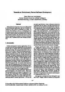
“alternate” FE going back to the RT. At last, traffic traces captured by the RT are inspected and only the 100Mbps data flow is taken into consideration; by subtracting the time of the first packet arrival on the “alternate path” from the time of the last packet arrival on the “preferred path”, we get the re-convergence time of the OSPF network. This test has been repeated 50 times according to each different grid size, from a 2x2 grid to a 13x13 one (Figure 7) and re-convergence times has been compared to standard ones collected from conventional software routers. Note that, as the grid size increases, the number of routers and the topological information required to describe them, increases in a quadratic form. By considering the workload of involved FEs and that each OSPF packet needs to be processed by a FE and the CE, the performance gap seems justified. 7 OSPF Convergence Time [s]
forwarding capacity of our distributed router prototype is heavily dependent on the line capacity of the network used to connect each element. As previously sketched, at the current stage of DROP development, we support a simple Ethernet IPN. Thus, we for all the test results here reported, we decided to used a star switched Gigabit Ethernet LAN in order to provide a sort of “backbone connectivity” for the distributed router, therefore, a single FE forwarding capacity is nearly close to the switching capacity of the LAN.
6 5 4 3 2 Monolithic SR 1
DROP prototype
0 4
9
16
25
36
49
64
81
100
121
144
169
Logical nodes in the emulated networks [#]
Figure 7. DR vs. standard SR OSPF re-convergence times.
B. Architectural Tests and Bottlenecks Distributed router architectures, like the one adopted in DROP, generally lead to remarkably enlarge the working RIB and the FIB sizes. This because the aggregation of more network elements (which correspond in our case to multiple SRs) generally causes the increase of router’s network interface, and consequently of neighboring networks and devices. From a simplistic point of view, the RIB managed by the DROP CEC can be considered as the addition (or better the aggregation) of the RIBs that each SR should manage when working without the DROP framework (and, then, as monolithic router). The synthesis process, needed to obtain the FIB of each FEs from the overall DROP RIB, is quite complex, and its behavior strictly depends from different parameters, like the protocols enabled, the network topology, etc.. However, it is reasonable to suppose that if RIB size raises, also the number of the FIB entries will increase. Moreover, given the DROP structure and architecture, all FEs will have FIBs with the same sizes. This because for each possible destination, known to the DROP router, each FE have to know the relative local output port, or to which FE that port belongs. All this certainly can be thought as an architectural bottleneck, which relates the number of the addable SRs and network interfaces with the working RIB and FIB sizes. In more detail, the FIB increase can cause a SR performance decay, due to the increase of IP lookup times (see [19] for
7 more details). In order to quantify this performance decay, we show in Figure 8 the maximum throughput values (by using only a single core/CPU of a SW) according to an increasing number of FIB entries. Note that each test has been repeated a certain number of times in order to obtain a results confidence of 3%. The traffic flows used is composed by 64B sized datagrams with a random destination address, which equally match each routing entry in the FIB.
[7]
[8]
[9] [10]
[11]
1400
[12] Throughput [kpps]
1200 1000
[13]
800 600
[14]
400
[15]
200 0 1
4
16
64
256
1024
4096
16384
Number of random FIB entries [#]
Figure 8. Tradeoff between FIB size and forwarding performance.
VI. CONCLUSION In this paper, we explored and studyed a new open-source SW framework, namely Distributed SW ROuter Project (DROP), which aims at developing and enabling a novel distributed paradigm for IP-router control and management. DROP is partially based on the main guidelines of the IETF ForCES standard (and can be also considered as its sole opensource realization), and it allows building logical network nodes through the aggregation of multiple SRs, which can be devoted to packet forwarding or to control operations. We also provided some performance evaluation through some control plane tests as defined in [17], and we discussed some architectural bottlenecks, which arise from the current DROP developments. REFERENCES [1]
[2]
[3] [4]
[5]
[6]
K. Argyraki, S. A. Baset, B.-G. Chun, K. Fall, G. Iannaccone, A. Knies, E. Kohler, M. Manesh, S. Nedveschi, S. Ratnasamy, “Can Software Routers Scale?”, Proc. of the ACM SIGCOMM 2008 Workshop on Programmable Routers for Extensible Services of Tomorrow (PRESTO 2008), Seattle, WA, USA, pp. 21-26. R. Bolla, R. Bruschi, “PC-based Software Routers: High Performance and Application Service Support”, Proc. of the ACM SIGCOMM 2008 Workshop on Programmable Routers for Extensible Services of Tomorrow (PRESTO 2008), Seattle, WA, USA, pp. 27-32. Distributed SW ROuter Project (DROP), homepage and source code at http://www.tnt.dist.unige.it/drop. A. Bianco, J. Finochietto, M. Mellia, F. Neri, G. Galante, “Multistage Switching Architectures for Software Routers,” IEEE Network "Advances in Network Systems", vol. 21, no. 4, pp. 15-21, July 2007. W. Wang et al., “Design and Implementation of an Open Programmable Router Compliant to IETF ForCES Specifications,” Proc. of the 6th Int. Conf. on Networking, 2007 (ICN '07), pp.82-82, Apr. 2007. O. Hagsand, M. Hidell, P. Sjodin, “Design and Implementation of a Distributed Router”, Proc. of the 5th IEEE International Symposium on Signal Processing and Information Technology, 2005 (ISSPIT ‘05), pp. 227-232, Dec 2005.
[16] [17] [18] [19]
J. Biswas et al., “The IEEE P1520 Standards Initiative for Programmable Network Interfaces,” IEEE Communications Magazine, Vol. 36, Oct. 1998, pp.64-72. L. Yang, R. Dantu, T. A. Anderson, and R. Gopal, “Forwarding and Control Element Separation (ForCES) Framework”, IETF RFC 3746, Apr. 2004. H. Khosravi, T. A. Anderson, “Requirements for Separation of IP Control and Forwarding”, IETF RFC 3654, Nov. 2003. R. Bolla, R. Bruschi, “Linux Software Router: Data Plane Optimization and Performance Evaluation”, Journal of Networks (JNW), Academy Publisher, vol. 2, no. 3, pp. 6-11, 2007. S. Radhakrishnan, “Linux – Advanced networking overview”, http://qos.ittc.ku.edu/howto.pdf. K. Wehrle, F. Pählke, H. Ritter, D. Müller, M. Bechler, “The Linux Networking Architecture: Design and Implementation of Network Protocols in the Linux Kernel”, Pearson Prentice Hall, Upper Saddle River, NJ , USA, 2004. M. Handley, O. Hodson, E. Kohler, “XORP: an open platform for network research”, ACM SIGCOMM Computer Communication Review, Vol. 33 Issue 1, Jan 2003, pp. 53-57. IETF Forwarding and Control Element Separation (forces) working group. http://www.ietf.org/html.charters/forces-charter.html. J. Salim, H. Khosravi, A. Kleen, A. Kuznetsov, “Linux Netlink as an IP Services Protocol,” IETF RFC 3549, July 2003. The GNU Quagga Routing suite, http://www.quagga.net. V. Manral, R. White, A. Shaikh, “Benchmarking Basic OSPF Single Router Control Plane”, IETF RFC 4061, Apr. 2005. V. Manral, R. White, A. Shaikh, “OSPF Benchmarking Terminology and Concepts”, IETF RFC 4062, Apr. 2005. R. Bolla, R. Bruschi, “The IP Lookup Mechanism in a Linux Software Router: Performance Evaluation and Optimizations”, Proc. of the 2007 IEEE Workshop on High Performance Switching and Routing (HPSR 2007), New York, NY, USA.