Abstract. In this paper, we extend our previous result on designing a single-axis maglev guiding system into a more involved work of designing a dual-axis ...
WePll
Proceedings of the 38” Conference on Decision & Control Phoenix, Arizona USA December 1999
18:OO
Dual-Axis Maglev Guiding System Modeling and controller Design for Wafer Transportation Mei-Yung Chen’, Ming-Jyh Wang‘, Li-Chen FU’?’ 1.R242, Department of Electrical Engineering, National Taiwan
University, Taipei, Taiwan, Republic of China. 2.R.533, Department of Computer Science and Information Engineering, National Taiwan University, Taipei, Taiwan, Republic of China.
Abstract In this paper, we extend our previous result on designing a single-axis maglev guiding system into a more involved work of designing a dual-axis positioning system. First of all, important issues on how to construct the mechanism of the dual-axis positioning system are addressed. Then, the dynamics of the dual-axis maglev guiding system are analyzed. According to the derived analytic model, which is subject to unknown system parameters, an adaptive controller that can control the wafer carrier at the desired target point of each axis with full alignment is developed. From the simulation results, good performance of regulation for guiding-axis and of tracking for positioning-axis is achieved.
Keywords: Dual-axis Maglev, Hybrid magnet, Adaptive control, Precision positioning
1. Introduction Recently, magnetic levitation is considered as one of the most suitable ways to achieve the high precision transportation. By Hollis et al.[1][2], it creates a stable state without any mechanical contact when the gravitational force is solely counterbalanced by magnetic forces. Of course, such contact-fiee levitation has to be enforced for all DOFs of the rigid body. Often, a distinction is made between magnetic suspension and magnetic levitation. The former refers to systems based on attractive magnetic forces whereas the latter based on repulsive ones. However, this restricted sense of the two terms does not cover all types of contact-free magnetic support. Therefore, it is the current trend to use the term ‘levitation’ in a more general sense, and to abbreviate “magnetic levitation” as ‘maglev’ in short. Previous work in maglev system spans many fields. A large volume of literature has been published. Some well known fields include maglev transportation[3][4], wind tunnel levitation[5], magnetic bearings[6], and antivibration tables[7]. Here, however, we will only investigate the maglev techniques for the field of short-range travel with precision positioning and then design and implement a prototype maglev system to verify its high performance. 0-7803-5250-5/99/$10.00 0 1999 IEEE
In our foregoing research [9][10], we have analyzed the dynamics of a maglev guiding system and derived its analytical model with full DOFs (degrees-of-freedom). Then, an adaptive controller which deals with unknown parameters is proposed there to regulate the five DOFs in that system. The guiding system including sensors and drivers is actually implemented. From the experimental results, satisfactory performance including stiffness and high resolution has been achieved. In this paper, a dual-axis maglev positioning system is developed, based on the above-mentioned work on the single-axis guiding system. Furthermore, an adaptive controller which achieves both the guiding goal and the positioning goal is developed. Simulation results are provided to demonstrate the feasibility of this proposed design of a dual-axis maglev positioning system. The organization of this paper is as follows. Section 2 describes the design aspects of the hereby proposed prototype system, and provides a detailed mathematic model. In section 3, an adaptive controller for the prototype maglev system is developed which can achieve the regulating objective for guiding and the tracking objective for positioning. Section 4 presents extensive simulation results to demonstrate the effectiveness of the system design including the adaptive controller. Some discussion is also made in section 4.Finally, conclusions are drawn in section 5.
2.System Description and Modeling In this section, the mechanical structure of a maglev guiding system will be described. Its analytical model will be derived and analyzed. 2-1.Maglev Guiding System In a stepper, one often adopts a linear slide to support and to guide the wafer carrier. The system proposed here is featured in an active control to provide a contactless linear slide as mentioned, which however is different from the magnetic bearing of rotating machine. In our earlier work, a restricted version with one-axis has been proposed and is used as the ground work for the present two-axis design. For detailed design of that system, one can refer to [9]. In the later context, only brief review of the design is given.
2623
The features of this two-axis maglev guiding system include: (1) repulsive levitation, ( 2 ) hybrid magnets, (3) passive carrier and active track, (4) oblong coil concept and ( 5 ) four-track design. The 3D views of the dual-axis maglev system is shown as in Figs. 2-1. The carrier moves along the upper guiding tracks in the X-direction, whereas the upper guiding tracks moves along the lower guiding tracks in the Y-direction. The lower guiding system must levitate the upper guiding system which levitates the wafer carrier. To facilitate the design work, one must reduce the weight of the carrier and the upper guiding system together as much as possible. Also, reduction of the carrier weight is helpful to alleviate the dynamic coupling between the upper and the lower guiding subsystems while the carrier is moving along the upper guiding tracks. In the application to wafer transportation, the carrier with the wafer on it is light. Then, once the weight of the upper guiding subsystem is reduced, excessive coil currents or coil turns that leads to significant magnetic field can thus be avoided, which in turn alleviates the undesirable disturbance to the system. To achieve such weight reduction, the alternative adopted here is to place light rubber magnets inside the tracks to replace the need for large of number of coils which are heavy. The by-product of adding rubber magnets is the saving of the power consumption since now the major countergravitational force is attributed to the rubber magnets. Another way of achieving weight reduction is to reduce the length of the upper guiding tracks due to the fact that each levitation magnet beneath the carrier never traverses the full-length track so that portion of each track is in fact redundant as illustrated in Fig. 2.1.
repulsive levitation design yields two floating bodies which are laterally unstable but vertically stable, where the unstable modes can be decoupled from' the stable ones[9]; oonly two unstable DOFs with the long-range travel DOF for each floating body are considered here; thus totally 6 DOFs, three for lateral modes and the other three for vertical modes, are considered here; athe stiffness of the lower guiding tracks in vertical direction is strong enough or the weight of carrier is light enough so that the disturbances induced by the travel of the floating body can be neglected;
0
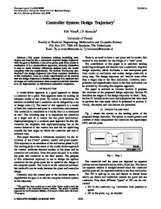
Figure 2-3: The front view of the upper guiding system levitation coils
stabilizing coils
I
I
left track
I \,
carrier
,
I
I
I
1
I
right track
Referring to the diagram of the mechanism of the upper guiding tracks, the rubber magnet and the winding coils inside each track together is called levitator, and the winding coils along the sides of the tracks are called stabilizers. Now considering only lateral directions here, we can observe that each levitation magnet beneath the carrier is subject to a destabilizing force Fd from the levitatior if the levitation magnet is not at the center of the track and a stabilizing force F, from stabilizer to center the whole carrier. Rewrite them in a more general from: Fd
Figure 2-1: 3D view of dual-axis maglev positioning system
=K ~ s
F, = -K,I
(2-1)
(2-2)
where Kd is a positive value named as destabilization force constant here, K, is a positive constant relating the stabilizing force, s is the displacement and I is the control current in stabilizer. If the vertical direction disturbance from the voice coil motor (VCM) is negligible(assume they are much smaller than the high stiffness levitator), the propulsion force can be simplified as: F, = K J
(2-3)
where K , is positive constant for the VCM andZ is the control current in VCM.
2-2.Modeling of Dual-Axis Maglev Positioning System From the structure as mentioned above, there obviously exists inevitable coupling between the guiding axes and the propulsion axes, and we can not control them independently. Here, we will derive a dual-axis model including the dynamics of the top carrier and those of the upper guiding system tracks, but concentrate on the unstable modes. For ease of later reference, we later will refer to this mechanism as a dual-axis model for two floating bodies. Before modeling, several assumptions must be made here in order to simplify the modeling process [SI, namely:
In Fig. 2-3, we let the upper floating body (carrier) and the lower floating body (upper guiding tracks) undergo displacements X,,Y,,B, and x, ,Y, ,oM , respectively, where X , and Y, are long-travel movements. Here, XYZ is marked as the global coordinate system with Z pointing out of paper. are chosen to be The local coordinate x,,,y,,z, ,x,y,z, coincident with the carrier's and the upper guiding track's principal axes, respectively, so that the products of inertia can be zero. For simplicity, we further assume the forces applied to the levitation magnets beneath the carrier board are concentrated on their central point.
2624
where F,,,,,F,,, are stabilizing force caused by inner pair of stabilizer and outer pair of stabilizer in lower body, respectively; Fmdl,Fmdo are destabilizing force caused by inner levitators and outer levitators in lower body, respectively;F,, is exerted by VCM in lower body; f , , , I,, and I,, are control current in inner stabilizer, outer stabilizer and VCM, respectively. The equations of motion for the upper body after substitution of Eq. (2-7) into Eqs.(2-4) and (2-5) become:
To obtain the equations of motion for a rigid body, we have
where F and T designate the external force and torque, respectively, whereas m and J symbolize the mass and the inertia with respect to the z axis of rigid body, respectively. The positions of levitation magnets are shown as Fig. 24. Then, the relative displacements of the levitation magnets in the upper body in xMyMzM coordinate system can be obtained by:
& , = ~ ~ , + F , ~ ~ + F , d , + F , d+ cFo,~,s MidM
.tu,=-2(FsI+F,,+F,d,+F,,sidM +F,,co& -&)-%i+Ed&
Jmem =%mo+&dc&
(2-8)
c0s8m-&)
where m,J , are the mass and moment of inertia of the upper body, respectively.
[
where T(0)s
'Os'
-sin0
Here, we turn to derive the equations of motion for the lower body. The relative displacements of lower body magnets in the ground coordinates are
is the transformation matrix
cos0
and (a,b) means the levitation magnets in the upper body. We have grouped the stabilizers into inner pair and outer pair, and similarly for levitators. Forces from the lower body to the upper body from Eqs. (2-1) to (2-3) are: IFmsi = -K,Imi(inner
Y direction :
FmS,= -K,,f,,(outer Fmdi = Kmd Dy (-dml
where T(B)=
pair) pair)
(2-7)
,-dm2
[
-sin0
cos0
is the transformation matrix
and (ab) means the position of the levitation magnets position mounted in lower body. Forces from the ground tracks to the lower body from Eqs.(2-1) to (2-3) are:
Y direction: FMc= KMcIMc
where FMsl, FMm are stabilizing force caused by inner pair of stabilizer and outer pair of stabilizer in the ground tracks, respectively. FMd,, FMdo are destabilizing caused force by inner levitator and outer levitator in the ground tracks, respectively; FMc is exerted by VCM in the ground; lMl, lM,and JMc are control current in inner stabilizer, outer stabilizer and VCM, respectively, The equations of motion for the lower carrier after substitution of Eq. (2-10) into Eqs. (2-4) and (2-5) can be obtained by:
X
Figure 2-3: Relative motions of the maglev system Y
M
- XFM>i+
FM~u+FMd~+FM~A+2(Fmsi+ Fmso+ Fmdi+FmdA
-F,,cos& kifM= K M ~ ~ ~ - ~ F , s , + F , , , + F ~ ~-FmC l+F SinOM ~~~cO~~ J f i M = q F M ~ ~ + F M d A d M l cOdM -qFMAi+FMdt)dMl
- 2(Fmx>+ L-
Fmd$ox-2(FmAi+
cOdM
Fmdt)'ix
(2-1 1) I
where Figure 2-4: The positions of levitation magnets in dual-axis maglev system
2625
and M , J, are the mass and moment of inertia of the lower
(3-2)
p'
body, respectively. The term [lm,lo,, is the displacement of an outer track levitation magnet mounted on the upper body in x,y,zM coordinate system, whereas the term [l,,l,,,p' is that of an inner track one. Assume that Ym - Y, ,X, ,em and ,6 are small displacements, so that the higher order terms is set to zero and sine,,, E em,cOseMz ],sineME ,6 and cos6, E 1. After substituting and simplifying the equations of the motions of whole system, one can obtain the following dynamic model:
-
Inkm-
4Km&%(6m
Mi,;,
Mj;, JdM
K2
K3
K4
KMd K5
KMcr
(3-3)
K 6 r
After that, the model in Eq. (2-12) can be transformed into:
(3-4)
DX = f(x,K)+ B(x,K)u
whereD=diag(m,Mm/(M+rn),J,,M,M,J,)>O
f(x,K) =
4KmAYm -yM)-4KJm6M
Jmim -
=[KI
Km
Kmd
-
0
my,
K=[Kms
-4K2x2 +4K2xIx6
-OM)
4K5d&,x6 - 4 K , ( x 2 - x l x 3 ) x I - 4 K 2 d i , ( x , - x 6 )
4KMJM
-4K,,,AYm -&)+4KmJm6~ 4K,&hBM -4KmAYm-Y,
K,
-Xm6m)Xm -41(,,Ji1(6m6 )-,
2Kix6
0
K ~ x , -2Kl
0
2Kl K,
0 K,
0
0 m/+mK6
2 K m s ( I m i + I m o )OM + K m c I m c - 2Kms ( I m i + I m o + K m c I m c 6 M
- 2 K m s(Imo -Imi W m i
+ -2K,Us(IMi
-
'MI
0
+ I M O ) ~ M KmcImc
+1Mo)-2Kms(1mi
KM~IM +~ 2Kms ( I m i + I m o ) -
-
-K3x6
'
"1
0
KmCImc6~
TM2
Also, the terms K T Iand KT2in B(x,K) are KTI
= 2 K l ( x i -x5)+K,(dm2 +dm3)(x3
KT2 = 2 K l d m l
+Kl(dm3
-x6)
-drn2)(x3 - x 6 )
Through the definition in Eq. (3-2), we can describe the control objective as: Let x2,x3,x4a n d x , approach to zero and xI and x5 approach to x, and y, , respectively, which implies the carrier will go to the desired position ( x d , y d ) and maintain the carrier and upper tracks at the center of the upper tracks and lower tracks, respectively.
In general, if on-line system identification can be achieved, the performance of the adaptive control should be better than that of the conservative robust control, especially in the case of a definite model structure with unknown parameters and variable loads. Nowadays, high speed PC-based controllers are more and more economical and reliable for intensive computations to realize a complex adaptive control scheme. This, therefore, motivates us to adopt an adaptive controller.
Before the derivation of control and adaptive laws, we define the state errors and parameter estimation errors as follows: (3-5)
3-1.Plant Model
In order to design controller more legibly, redefine the control inputs, states and unknown force constants as
3-2.Control Laws
2626
The system is feedback linearizable due to the nonzero
(3-4) if
JB(x,K)J= -8KIK:d,,,,d,,
K,
2K,x6
0
K3x6 -K3x6
-2KI
m/+,,,K, K6
2K,
In order to prove the stability of Eq. (3-10) with the control law Eq. (3-9) and adaptive law Eq. ( 3 - l l ) , we choose the Lyapunov function candidate V as: (3-12)
(3-7)
-
where g, > 0,Vi = 1 6 , whose time derivative can be evaluated as:
gi 'k,ki+ ETD%+i T ( x - Dx,) x, - 2 4 2 , -
where
-
1
1
+ iTf(x,k)+ kTB(x,k)u+ ETDk+iTD(v - ad)
- 2a2x2- a;x2 - 24x, - g x 3 V=
- 2 2 x -a:x4 4. j;, - 2 , ~ ~ :-a;& ~ - 2d6X6- a:x6
6
= ~ - d i s ~ Q i s i0 i=l
(3-13)
where si = [F~
iir, xd = [ i do o o
j;,
OF,
andQ, is positive definite and d, is the ith diagonal term of D which is positive. From Eqs. (3-12) and (3-13), it shows that V is a suitable Lyapunov function, and, by Lyapunov stability criteria, we conclude that ands, are all bounded, s, E L, and in turn S I E L, by referring back to Eq. (3-10). Thus, by using Barbalat's Lemma, we finally have that s, is asymptotically stable. That implies that %,$ go to zero as time goes to infinity. As a result, the control objectives described are achieved. The upper and the lower free bodies can stay at the center of tracks, and the carrier can reach to the desired position.
4.Simulation Results In this section, we will give some simulation results in accordance with the mathematical model we have derived so far. The simulation parameters are liste as the following table 4- 1 . Figures 4-1 and 4-2 give the simulation results with desired carrier position are xd =0.03m, y,, = -O.OSsin(2Q)m and xd = O.O5sin(30t)m, yd = -0.05sin(20t)m , respectively. The initial state conditions are given randomly, while initial values of system parameters are setting to the half of real simulation values. From simulation result, we can conclude that the carrier(upper free body) and upper guiding tracks(1ower free body) can be regulated at the center of tracks which levitate them and the carrier can go to the setting point or track the desired trajectory.
2627
I
Upper free body
Lower free body
(carrier)
(upper guiding tracks)
0.5Kg 0.04 Kg.m2
3Kg 0.5 Kg.m2
Mass Moment of inertia Stabilizing force constant
5.Conclusions 1
-12.6 N/A
= 0.07m, d,, = 0.09m,dm,= 0.16m Table 4-1: The simulation parameters
d,, = 0.08m, d,, 11
........-:....
0
E
I
.........:. . . . . . . . . . . . . .
0.05
.: .........
E
..........:........
. . . .
This research is sponsored by National Science Council, R.O.C., under the grant NSC 87-2213-E-002-092
O
........ :
-2
......:
-005
Acknowledgement
ra
,as
........:..........:.
2
In this paper, a short-range travel dual-axis maglev system is designed. A repulsive maglev system with four active guiding tracks is adopted here. Then, the system is treated as a multi-input multi-output system, and an adaptive controller is designed. From the simulation results, the system’s feasibility and effectiveness have been clearly demonstrated. The performance of regulation for guidingaxis and tracking for positioning-axis is achieved. This results can provide the fkrther design in non-contact magnetic positioning system.
.....: . ~.......
Bibliography R. L. Hollis, and S. E. Salcudean, “On the Design and Control of
E
5r{
O
0
0.3
.............
:
....
-0.05
0.2
0.2
0.1
0
a-
s o -
- 5 ~ 5
0.1
,MS
0.2
op+-++ 6
I
I
’F -1 i’l v l w 1 3
-%
0.2
0.1
0.1
0 2
0.1 ti”..