Duet: Cloud Scale Load Balancing with Hardware and Software Rohan Gandhi† Hongqiang Harry Liu∧ Y. Charlie Hu† Guohan Lu? Jitendra Padhye? Lihua Yuan? Ming Zhang? Microsoft? , Purdue University† , Yale University∧
ABSTRACT Load balancing is a foundational function of datacenter infrastructures and is critical to the performance of online services hosted in datacenters. As the demand for cloud services grows, expensive and hard-to-scale dedicated hardware load balancers are being replaced with software load balancers that scale using a distributed data plane that runs on commodity servers. Software load balancers offer low cost, high availability and high flexibility, but suffer high latency and low capacity per load balancer, making them less than ideal for applications that demand either high throughput, or low latency or both. In this paper, we present D UET, which offers all the benefits of software load balancer, along with low latency and high availability – at next to no cost. We do this by exploiting a hitherto overlooked resource in the data center networks – the switches themselves. We show how to embed the load balancing functionality into existing hardware switches, thereby achieving organic scalability at no extra cost. For flexibility and high availability, D UET seamlessly integrates the switch-based load balancer with a small deployment of software load balancer. We enumerate and solve several architectural and algorithmic challenges involved in building such a hybrid load balancer. We evaluate D UET using a prototype implementation, as well as extensive simulations driven by traces from our production data centers. Our evaluation shows that D UET provides 10x more capacity than a software load balancer, at a fraction of a cost, while reducing latency by a factor of 10 or more, and is able to quickly adapt to network dynamics including failures. Categories and Subject Descriptors: C.2.4 [ComputerCommunication Networks]: Distributed Systems—Network Operating Systems General Terms: Design, Performance Keywords: Load Balancing, Datacenter, SDN
1.
INTRODUCTION
A high performance load balancer is one of the most important components of a cloud service infrastructure. Services in the data Permission to make digital or hard copies of all or part of this work for personal or classroom use is granted without fee provided that copies are not made or distributed for profit or commercial advantage and that copies bear this notice and the full citation on the first page. Copyrights for components of this work owned by others than ACM must be honored. Abstracting with credit is permitted. To copy otherwise, or republish, to post on servers or to redistribute to lists, requires prior specific permission and/or a fee. Request permissions from
[email protected]. SIGCOMM’14, August 17–22, 2014, Chicago, Illinois, USA. Copyright 2014 ACM 978-1-4503-2836-4/14/08 ...$15.00. http://dx.doi.org/10.1145/2619239.2626317 .
center scale by running on multiple servers, each with an individual direct IP (DIP). The service exposes one or more virtual IP addresses (VIP) outside the service boundary. The load balancer receives the traffic destined for the VIP, splits it among the DIPs, and routes it to the individual DIPs using IP-in-IP encapsulation. The load balancer thus touches every packet coming into the data center from the Internet, as well as a significant fraction of all intra-DC traffic. This traffic volume induces heavy load on both data plane and control plane of the load balancer [17]. The performance and reliability of the load balancer directly impact the latency, throughput and the availability of the cloud services hosted in the DC. Traditional load balancers are dedicated hardware middleboxes [1, 4] that are very expensive. In contrast, Ananta [17] is a software load balancer that runs on commodity servers. Ananta consists of a central controller, and several software Muxes (SMux) that provide a distributed data plane. Each SMux maintains all VIPto-DIP mappings, and implements traffic splitting and encapsulation functionality in software. The Ananta architecture is flexible, highly scalable and ensures high availability. However, software load balancers have two fundamental limitations, both of which stem from the fact that they process the packets in software. First, processing packets in software limits capacity. Experiments show that the CPU on individual Ananta SMux becomes a bottleneck once the incoming traffic exceeds 300K packets per second. While the aggregate capacity of software load balancer can be scaled out by adding more servers, doing so raises cost. For example, handing 15Tbps traffic (typical for a mid-sized DC) requires over 4000 SMuxes, costing over USD 10 million. Second, processing packets in software incurs high, and highly variable latency. An Ananta SMux, handling as little as 100K packets per second can add anywhere from 200µsec to 1ms of latency. Applications such as algorithmic stock trading and high performance distributed memory caches demand ultra-low (a few microseconds) latency within the data center. For such applications, the latency inflation by the software load balancer is not acceptable. In this paper, we propose D UET, which addresses these two drawbacks of software load balancers. D UET uses existing switch hardware in data centers to build a high performance, in-situ, organically scalable hardware load balancer and seamlessly combines it with a small deployment of software load balancer for enhanced availability and flexibility. D UET is based on two key ideas. The first idea is to build a load balancer from existing switches in the data center network. The key insight is that the two core functions needed to implement a load balancer – traffic splitting and packet encapsulation – have long been available in commodity switches deployed in data center networks. Traffic splitting is supported using ECMP, while
2.
BACKGROUND AND MOTIVATION
We provide background on load balancing functionality in DCs, briefly describe a software-only load balancer architecture (Ananta), and point out its shortcomings.
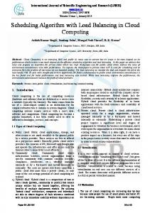
Switch No-load
200k 300k
400k 450k
1 CDF
0.8 0.6 0.4 0.2 0 0.1
1 Latency (msec)
10
(a) End-to-end latency CPU Utilization(%)
packet encapsulation is supported using tunneling. However, it is only recently that the switch manufacturers have made available APIs that provide detailed, fine-grained control over the data structures (ECMP table and tunneling table) that control these two functions. We re-purpose unused entries in these tables to maintain a database of VIP-to-DIP mappings, thereby enabling the switch to act as a Mux in addition to its normal forwarding function. This gives us an in-situ, hardware Mux (HMux) – without new hardware. Since splitting and encapsulation are handled in the data plane, the switch-based load balancer incurs low latency (microseconds) and high capacity (500 Gbps). While HMuxes offer high capacity, low latency and low cost, the architecture is less flexible than software load balancers. Specifically, handling certain cases of switch failures is challenging (§5.1). Thus, our second idea is to integrate the HMuxes with a small deployment of SMuxes, to get the best of both worlds. We make the integration seamless using simple routing mechanisms. In the combined design, most of the traffic is handled by the switchbased hardware load balancer, while software load balancer acts as a backstop, to ensure high availability and provide flexibility. Compared to dedicated hardware load balancers, or pure software load balancers (Ananta), D UET is highly cost effective. It load-balances most of the traffic using existing switches (HMuxes), and needs only a small deployment of software load balancer as a backstop. Because most of the traffic is handled by the HMuxes, D UET has significantly lower latency than software load balancers. At the same time, use of software load balancer enables D UET to inherit high availability and flexibility of the software load balancer. To design D UET, we addressed two main challenges. First, individual switches in the data center do not have enough memory to hold the entire VIP-to-DIP mapping database. Thus, we need to partition the mappings among the switches. We devise a simple greedy algorithm to do this, that attempts to minimize the “leftover” traffic (which is perforce handled by the software load balancer), while taking into account constraints on switch memory and demands of various traffic flows. The second challenge is that this mapping must be regularly updated as conditions change. For example, VIPs or DIPs are added or removed by customers, switches and links fail and recover etc. We devise a migration scheme that avoids memory deadlocks and minimizes unnecessary VIP movement. We evaluate D UET using a testbed implementation as well as extensive, large-scale simulations. Our results show that D UET provides 10x more capacity than the pure software load balancer, at a fraction of the SMux cost, while also reducing the latency inflation by 10x or more. Additionally, we show that D UET quickly adapts to the network dynamics in the data center including failures. In summary, the paper makes the following three contributions. First, We characterize the conditions, design challenges, and design principles for moving load balancing functionality directly into hardware switches which offer significantly lower latency and higher capacity than software servers. Second, we present the design and implementation of a switch-based load balancer. To the best of our knowledge, this is the first such design. Third, we show how to seamlessly combine the switch-based load balancer with software load balancer to achieve high availability and flexibility. Again, to the best of our knowledge, this is the first “hybrid” load balancer design.
100 80 60 40 20 0 No-load 200k 300k 400k 450k Traffic (Packets/sec)
(b) CPU Utilization Figure 1: Performance of software Mux.
A DC typically hosts multiple services. Each service is a set of servers that work together as a single entity. Each server in the set has a unique direct IP (DIP) address. Each service exposes one or more virtual IP (VIP) outside the service boundary. The load balancer forwards the traffic destined to a VIP to one of DIPs for that VIP. Even services within the same DC use VIPs to communicate with each other, since the indirection provided by VIPs offers several benefits. For example, individual servers can be maintained or upgraded without affecting dependent services. Management of firewall rules and ACLs is simplified by expressing them only in terms of VIPs, instead of DIPs, which are far more numerous and are subject to churn. The key to the efficient functioning of the indirection architecture is the load balancer. A typical DC supports thousands of services [17, 9], each of which has at least one VIP and many DIPs associated with it. All incoming Internet traffic to these services and most inter-service traffic go through the load balancer. As in [17], we observe that almost 70% of the total VIP traffic is generated within DC, and the rest is from the Internet. The load balancer design must not only scale to handle this workload but also minimize the processing latency. This is because to fulfill a single user request, multiple back-end services often need to communicate with each other — traversing the load balancer multiple times. Any extra delay imposed by the load balancer could have a negative impact on end-to-end user experience. Besides that, the load balancer design must also ensure high service availability in face of failures of VIPs, DIPs or network devices.
2.1
Ananta Software Load Balancer
We first briefly describe the Ananta [17] software load balancer. Ananta uses a three-tier architecture, consisting of ECMP on the routers, several software Muxes (SMuxes) that run on commodity servers, and are deployed throughout the DC, and a host agent (HA) that runs on each server. Each SMux stores the VIP to DIP mappings for all the VIPs configured in the DC. Using BGP, every SMux announces itself
to be the next hop for every VIP. Incoming packets for a VIP are directed to one of the SMuxes using ECMP. The SMux selects a DIP for the VIP, and encapsulates the packet, setting the destination address of the outer IP header to the chosen DIP. At the DIP, the HA decapsulates the incoming packet, rewrites the destination address and port, and sends it to server. The HA also intercepts outgoing packets, and rewrites their IP source addresses from the DIP to the VIP, and forwards the direct server return (DSR). Ananta can support essentially an unlimited number of VIPs and DIPs, because it stores this mapping in the large main memory on commodity servers. While a single SMux in Ananta has limited capacity (due to software processing), Ananta can still scale to handle large volumes of traffic. First, Ananta deploys numerous SMuxs, and relies on ECMP to split the incoming traffic among them. Second, DSR ensures that only the incoming or the VIP traffic goes through the load balancer. Ananta also includes a mechanism called fast path to enhance scalability. Fast path allows all inter-service traffic to directly use DIPs, instead of using VIPs. However, this negates the benefits of the VIP indirection. For example, if fast path is enabled, service ACLs have to be expressed in terms of DIPs. In summary, implementing parts of load balancing functionality in software allows Ananta to be highly scalable and flexible. However, processing packets in software is also the Achilles heel for Ananta, because it adds latency, and limits the throughput, as we discuss next.
without the need for any additional hardware. However, the HMux design suffers from certain shortcomings. Thus, our second idea is to combine the HMux with Ananta-like software Mux (SMux). The combined system is called D UET in which the SMux acts as a backstop for the HMux. We now describe the design of HMux. To simplify the description, we will assume that the DC is not virtualized, i.e., one DIP corresponds to one server. The changes required to support VMs are described in §5.2.
2.2
3.1
Limitations of Software Load Balancer
Figure 1(a) shows the CDF of the RTTs for the VIP traffic loadbalanced by a production Ananta SMux as traffic to the VIP varies between 0 and 450K packets/sec. Even at zero load the SMux adds a median latency of 196µsec. The latency variance is also significant, with the 90th percentile being 1ms. The median RTT (without load balancer) in our production DCs is 381µsec, so the inflation in latency is significant for the intra-DC traffic, which accounts for 70% of the total VIP traffic. (For the remaining traffic from the Internet, it is a lesser problem due to larger WAN latencies). The high latency inflation and high latency variability result from processing the packets in software. We also see that the added latency and the variance get much worse at higher load. The results also illustrate that an individual SMux instance has low capacity. Beyond 300K packets/sec, the CPU utilization reaches 100% (Figure 1(b)). Thus, for the hardware SKU used in our DCs, each SMux can handle only up to 300K packets/sec, which translates to 3.6 Gbps for 1,500-byte packets. At this rate, supporting 15 Tbps VIP traffic for a mid-sized (40K servers) DC would require over 4K SMuxes, or 10% of the DC size; which is unacceptable1 .
3.
DUET: CORE IDEAS
In the previous section, we saw that while software load balancers are flexible and scalable, they suffer from low throughput and high latency. In this paper, we propose a new design called D UET that offers scalability, high throughput and low latency, at a small fraction of the software load balancer’s cost. D UET is based on two novel ideas. First, we leverage idle resources of modern, commodity data center switches to construct a hardware load balancer. We call this design Hardware Mux (HMux). HMux offers microsecond latency, and high capacity, 1 Newer technologies such as direct-packet IO and RDMA may help match packet processing capacity of the SMux to that of the NIC (10 Gbps), but they may not match packet processing capacity of the switch (600 Gbps+) as we explain in § 3.1.
Forwarding Table Destination IP 10.0.0.0/32 11.0.0.0/32
ECMP Table Index
Tunneling Table Encap IP
0 1 2 3
100.0.0.1 100.0.0.2 110.0.0.1 110.0.0.2 DIP
VIP
VIP
100.0.0.2 10.0.0.0 Data
10.0.0.0 Data HMUX
Figure 2: Storing VIP-DIP mapping on a switch.
HMux
Ananta’s SMux implements two key functions to load balance traffic: (1) for each VIP, split traffic equally among its DIPs, and (2) use IP-in-IP encapsulation to route the VIP traffic to the corresponding DIPs. Both of these functions have long been available on commodity switches, i.e., traffic splitting is supported using ECMP and IP-in-IP encapsulation is supported using tunneling. However, major switch vendors have only recently started to provide the APIs for fine-grained control over ECMP and tunneling functionality. Our key insight is that by carefully programming the ECMP and tunneling tables using these new APIs, we can make a commodity switch act as a hardware Mux (HMux), in addition to its normal functionality. In fact, this can be easily done on most of the switches used in our DCs today. Figure 2 shows the HMux design. A packet arriving at a switch goes through a processing pipeline. We focus on three tables used in the pipeline. The packet matches one entry in the host forwarding table which then points to multiple ECMP table entries. These ECMP table entries correspond to multiple next hops for the packet2 . The actual next hop for the packet is selected by using the hash of the IP 5-tuple to index into the ECMP table. The tunneling table enables IP-in-IP encapsulation by storing the information needed to prepare the outer IP header for a given packet. To construct HMux, we link the ECMP and tunneling functionalities. Consider a packet destined for VIP 10.0.0.0 that arrives at the HMux. There are two DIPs (100.0.0.1 and 100.0.0.2) for this VIP. The host forwarding table indicates that the first two entries in the ECMP table pertain to this VIP. The ECMP entries indicate that packets should be encapsulated, and point to appropriate entries in the tunneling table. The switch encapsulates the packet using IP-inIP encapsulation, and the destination address in the outer IP header is set to the DIP address specified in the tunneling table entry. The packet is then forwarded to the appropriate interface. Thus, at the expense of some entries in the host forwarding, ECMP and tunneling tables, we can build a load balancer using 2 The information is split between ECMP group table and ECMP table; we omit such details due to lack of space.
Core
C1
Agg
A1
C2
A2
HMux: VIP1 assigned
A3
C3
A4
A5
A6
ToR
T1
T2
T3
T4
T5
T6
Servers
S1
SMux
D1
S2
D2
D3
SMux: All VIPs assigned
added and hence the aggregate capacity of HMuxes will also increase proportionally.
C4 HMux: VIP2 assigned
Host Agent DIP
Figure 3: D UET architecture: VIPs are partitioned across different HMuxes — VIP1 and VIP2 are assigned to HMux C2 and A6 . Additionally, SMuxes act as backstop for all the VIPs. Every server (apart from SMuxes) runs host-agent that decapsulates the packets and forwards to the DIP. Links marked with solid lines carry VIP traffic, and links with dotted lines carry DIP traffic.
3.3
3.3.1 commodity switches. In fact, if all the VIP-to-DIP mappings are stored on every top-of-rack (ToR) switch as well as every access switch, this HMux design can provide load balancing functionality to all intra-DC and inter-DC traffic. However, the amount of space available in the three tables is limited, raising two distinct issues. Number of VIPs: The first problem is the size of the host forwarding table. The switches in our DC have 16K entries in the host table. The host table is mostly empty, because it is used only for routing within a rack. But even the 16K entries may not be enough to hold all VIPs in a large DC. One way to address this problem is by using longest prefix match (LPM) forwarding table. However, LPM table is heavily used for routing within and across DCs, and is not available to be used for load balancing. We support higher number of VIPs using SMuxes as explained in §3.3. Number of DIPs: The second problem concerns the sizes of the ECMP and tunneling tables. ECMP table typically holds 4K entries, and is mostly empty (see § 9). The tunneling table typically holds 512 entries. In our DC, few applications use tunneling, so these entries are mostly free as well. The number of DIPs an individual HMux can support is the minimum of the number of free entries in the ECMP and the tunneling tables (see Figure 2). Thus, an individual HMux can support at most 512 DIPs. This is orders of magnitude smaller than the total number of DIPs. We address this challenge next.
3.2
DUET: HMux + SMux
While partitioning helps increase the number of DIPs HMux can support, that number still remains limited. The HMux design also lacks the flexibility of SMux, because VIPs are partitioned and “pinned” to specific HMuxes. This makes it challenging to achieve high VIP availability during network failures. Although replicating VIP across a few switches may help improve failure resilience, it is still hard to achieve the high availability of Ananta because Ananta stores the complete VIP-DIP mappings on a large number of SMuxes. This motivates us to architect D UET— a new load balancer design to fuse the flexibility of SMux and the high capacity and low latency of HMux.
Design
D UET’s goal is to maximize VIP traffic handled using HMux, while using SMux as a backstop. Thus, besides an HMux on each switch, D UET also deploys a small number of SMuxes on commodity servers (figure 3). The VIPs are partitioned among HMuxes as described earlier. In addition, each SMux announces all the VIPs. The routing protocol preferentially routes VIP traffic to HMux, ensuring that VIP traffic is primarily handled by HMux – thereby providing high capacity and low latency. In case of HMux failure, traffic is automatically diverted to SMux, thereby achieving high availability. To ensure that existing connections do not break as a VIP migrates from HMux to SMux or between HMuxes, all HMuxes and SMuxes use the same hash function to select DIPs for a given VIP. The preferential routing to HMux can be achieved in several ways. In our current implementation, SMux announces the VIPs in aggregate prefixes, while HMux announces /32 routes to individual VIPs. Longest prefix matching (LPM) prefers /32 routes over aggregate prefix routes, and thus directs incoming VIP traffic to appropriate HMux, unless that HMux is unavailable. The number of SMuxes needed depends on several factors including the VIP traffic that cannot be assigned to HMux due to switch memory or link bandwidth limits (§4), the VIP traffic that failovers to SMux due to HMux failure (§5.1), and the VIP traffic that is temporarily assigned to SMux during VIP migration (§4.2). We estimate it based on historical traffic and failure data in DC.
Partitioning
We address the problem of limited size of ECMP and tunneling tables using two mechanisms: (1) We divide the VIP-to-DIP mapping across multiple switches. Every switch stores only a small subset of all the VIPs, but stores all the DIPs for those VIPs. This way of partitioning ensures all the traffic for a particular VIP arrives at a single switch and the traffic is then equally split among the DIPs for that VIP. (2) Using BGP, we announce the VIPs that are assigned to the switches, so that other switches can route the VIP packets to the switch where the VIP is assigned. Figure 3 illustrates this approach. VIP1 has two DIPs (D1 and D2 ), whereas VIP2 has one (D3 ). We assign VIP1 and VIP2 to switches C2 and A6 respectively, and flood the routing information in the network. Thus, when a source S1 sends a packet to VIP1 , it is routed to switch C2 , which then encapsulates the packet with either D1 or D2 , and forwards the packet. Another key benefit of partitioning is that it achieves organic scalability of HMuxes — when more servers are added in the DC and hence traffic demand increases, more switches will also be
3.3.2
Benefits
The key benefits of D UET are summarized below. Low cost: D UET does not require any additional hardware – it uses idle resources on existing switches to provide load balancing functionality. D UET also requires far fewer SMuxes than Ananta, since SMuxes are used only as a backstop for HMuxes, and hence carry far less traffic. High capacity and low latency: this is because VIP traffic is primarily handled by HMux on switch. High availability: by using SMux as a backstop during failures, D UET enjoys the same high availability as Ananta. High limit on number of VIPs: If the number of VIPs exceeds the capacity of the host forwarding table (16K), the additional VIPs can be hosted on SMux. Traffic data (Figure 15) in our production DCs shows that VIP traffic distribution is highly skewed – most of the traffic is destined for a small number of “elephant” VIPs which can be handled by HMux. The remaining traffic to “mice” VIPs can be handled by SMux.
Notation V dv S, E R Ci ti,s,v Li,s,v Ui,s,v Ui,v M RUs,v
Explanation Set of VIPs Set of DIPs for the v-th VIP Set of switches and links respectively Set of resources (switches and links) Capacity of i-th resource v-th VIP’s traffic on i-th link, when it is assigned to s-th switch load (additional utilization) on i-th resource if v-th VIP is assigned to s-th switch Cumulative utilization of i-th resource if v-th VIP is assigned to s-th switch Cumulative utilization of i-th resource after v VIPs have been assigned Max. Resource Utilization (MRU) after v-th VIP is assigned to s-th switch
VIP Traffic
VIP Traffic
VIP Traffic
S1
S1
S1
(60%)
(60%)
(60%)
V1
V2
V2
V1
S2
S3
S2
S3
(60%)
(60%)
(60%)
(60%)
SMux
SMux
SMux
SMux
(a) Initial
(b) Final
S2
S3
V1,V2 V1,V2 SMux
SMux
(c) Through SMux
Figure 4: Memory deadlock problem during VIP migration. VIPs V1 and V2 both occupy 60% of switch memory each. The goal of migration is to migrate the VIPs from assignment in (a) to (b); D UET eliminates this problem by migrating VIPs through SMuxes, as shown in (c).
Table 1: Notations used in VIP assignment algorithm. These benefits can only be realized through careful VIP-switch assignment. The assignment must take into account both memory and bandwidth constraints on individual switches, as well as different traffic load of different VIPs. The assignment must dynamically adapt to changes in traffic patterns and network failures. In the next two sections, we describe how D UET solves these problems, as well as provides other load balancing functions.
4.
VIP ASSIGNMENT ALGORITHM
We formalize the VIP-switch assignment problem using the notations listed in Table 1. Input: The input to the algorithm includes the list of VIPs (V ), the DIPs for each individual VIP v (dv ), and the traffic volume for each VIP. The latter is obtained from network monitoring. The input also includes the network topology, consisting of a set of switches (S) and a set of links (E). The switches and links constitute the two types of resources (R) in the assignment. Each resource instance has a fixed capacity Ci , i.e., the link bandwidth for a link, and memory capacity that includes residual ECMP and tunneling table capacity available for D UET on a switch. To absorb the potential transient congestion during VIP migration and network failures, we set the capacity of a link to be 80% of its bandwidth. Objective: Find the VIP-switch assignment that maximizes the VIP traffic handled by HMux. As explained earlier, this will improve latency and reduce cost by cutting the number of SMux needed. We do not attempt to minimize the extra network propagation delay due to indirection because the propagation delay contributes only less than 30µsec of the 381µsec RTT in our DC. Constraints: Any VIP-switch assignment should not exceed the capacity of any of the resources. The VIP assignment problem is a variant of multi-dimensional bin-packing problem [10], where the resources are the bins, and the VIPs are the objects. Multi-dimensional bin-packing problems are NP-hard [10]. D UET approximates it with a greedy algorithm, which works quite well in our simulations based on real topology and traffic load of a large production network.
4.1
VIP Assignment
We define the notion of maximum resource utilization (MRU). We have two types of resource – switches and links. MRU represents the maximum utilization across all switches and links. Algorithm sketch: We sort a given set of VIPs in decreasing traffic volume, and attempt to assign them one by one (i.e., VIPs with most traffic are assigned first). To assign a given VIP, we consider all switches as possible candidates to host the VIP. Typically,
assigning a VIP to different switches will result in different MRU. We pick the assignment that results in the smallest MRU, breaking ties at random. If the smallest MRU exceeds 100%, i.e., no assignment can accommodate the load of the VIP, the algorithm terminates. The remaining VIPs are not assigned to any switch – their traffic will be handled by the SMuxes. We now describe the process of calculating MRU. Calculating MRU: We calculate the additional utilization (load) on every resource for each potential assignment. If the v-th VIP is assigned to the s-th switch, the extra utilization on the i-th link t where traffic ti,s,v is calculated based on the is Li,s,v = i,s,v Ci topology and routing information as the source/DIP locations and traffic load are known for every VIP. Similarly, the extra switch memory utilization is calculated as Ls,s,v = |dCvs| , i.e., the number of DIPs for that VIP over the switch memory capacity. The cumulative resource utilization when the v-th VIP is assigned to the s-th switch is simply the sum of the resource utilization from previously assigned (v-1) VIPs and the additional utilization due to the v-th VIP: Ui,s,v = Ui,v−1 + Li,s,v
(1)
The MRU is calculated as: M RUs,v = max(Ui,s,v ), ∀i ∈ R
4.2
(2)
VIP Migration
Due to traffic dynamics, network failures, as well as VIP addition and removal, a VIP assignment calculated before may become outof-date. From time to time, D UET needs to re-calculate the VIP assignment to see if it can handle more VIP traffic through HMux and/or reduce the MRU. If so, it will migrate VIPs from the old assignment to the new one. There are two challenges here: (1) how to calculate the new assignment that can quickly adapt to network and traffic dynamics without causing too much VIP reshuffling, which may lead to transient congestion and latency inflation. (2) how to migrate from the current assignment to new one. A simple approach would be to calculate the new assignment from scratch using new inputs (i.e., new traffic, new VIPs etc.), and then migrate the VIPs whose assignment has changed between the current assignment and the new one. To prevent routing black holes during VIP migration, we would use make-before-break — i.e., a VIP would be announced from the new switch before it is withdrawn from the old switch. This simple approach is called Non-sticky.
ToR
Agg
Core
Agg
ToR
A1
C1
A3
T2
A2
C2
A4
T3
Tunneling Table
Index 0 1 2
T1
Container-1
Container-2
HMUX VIP
Figure 5: When the VIP assignment changes from ToR T2 to T3 , only the links inside container-2 are affected. As a result, we can first select best ToR in a container based on the links within container, and then scan over all containers and remaining Core and Agg switches.
3 Recall that SMux announces all VIPs to serve as a backstop (§3.3.1)
Host-1
HA 20.0.0.1
VM-1 100.0.0.1 VM-2 100.0.0.2
Host-2
HA 20.0.0.2
VM-3 100.0.0.3
DIP
Figure 6: Load balancing in virtualized clusters.
5. The Non-sticky approach suffers from two problems. First, it may lead to transitional memory deadlock. Figure 4 shows a simple example where initially VIP V1 and VIP V2 are assigned to switches S2 and S3 , respectively, but swap positions in the new assignment. Further, either VIP takes 60% of the switch memory. Because of limited free memory, there is no way to swap the VIPs under the make-before-break approach. When there are a large number of VIPs to migrate, finding a feasible migration plan becomes very challenging. Second, even if there was no such deadlock, calculating a new assignment from scratch may result in a lot of VIP reshuffling, for potentially small gains. D UET circumvents transitional memory deadlocks by using SMux as a stepping stone. We first withdraw the VIPs that need to be moved from their currently assigned switches and let their traffic hit the SMux3 . We then announce the VIPs from their newly assigned switches, and let the traffic move to the new switches. This is illustrated in Figure 4(c) where both VIP’s (V1 and V2) traffic is handled by SMux during migration. Because SMux is used as a stepping stone, we want to avoid unnecessary VIP reshuffling to limit the amount of VIP traffic that is handled by SMux during migration. Hence, we devise a Sticky version of the greedy VIP assignment algorithm that takes the current assignment into account. A VIP is moved only if doing so results in significant reduction in MRU. Let us say that VIP v was assigned to switch sc in the current assignment, and the MRU would be the lowest if it is assigned to switch sn in the new assignment. We assign v to sn only if (M RUsc ,v − M RUsn ,v ) is greater than a threshold. Else we leave v at sc . Complexity: It is important for D UET to calculate the new assignment quickly in order to promptly adapt to network dynamics. Since all Li,s,v can be pre-computed, the complexity to find the minimum MRU (Equation 2) for VIP-switch assignment is O(|V | · |S| · |E|). This complexity can be further reduced by leveraging the hierarchy and symmetry in the data center network topology. The key observation is that assigning a VIP to different ToR switches inside a container will only affect the resource utilization inside the same container (shown in Figure 5). Therefore, when assigning a VIP, we only need to consider one ToR switch with the lowest MRU inside each container. Because ToR switches constitute a majority of the switches in the data center, this will significantly reduce the computation complexity to O(|V |·((|Score |+|Sagg |+|C|)·|E|+ |Stor | · |Ec |)). Here C and Ec denote the containers and links inside a container. Score , Sagg and Stor are the Core, Aggregation and ToR switches respectively.
Encap IP 20.0.0.1 20.0.0.1 20.0.0.2
PRACTICAL ISSUES
We now describe how D UET handles important practical issues such as failures and configuration changes.
5.1
Failure Recovery
A critical requirement for load balancer is to maintain high availability even during failures. D UET achieves this primarily by using SMuxes as a backstop. HMux (switch) failure: The failure of an HMux is detected by neighboring switches. The routing entries for the VIPs assigned to the failed HMux are removed from all other switches via BGP withdraw messages. After routing convergence, packets for these VIPs are forwarded to SMuxes, since SMuxes announce all VIPs. All HMux and SMux use the same hash function to select DIPs for a given VIP, so existing connections are not broken, although they may suffer some packet drops and/or reorderings during convergence time (