Since Bailey and Hubbard's pioneer work (Bailey and Hubbard, 1985), piezoelectric materials ..... f*(x,y,p) = s mf(x,~. t) exp(-pt) dt,. 0 where the inversion integration is taken over the usual Bromwich path. ...... John Wiley & Sons, New York. Baker ... Bailey, T. and Hubbard, Jr, J. E. (1985) Distributed piezoelectric-polymer.
J. Mech. Phys. Solids, Vol. 44, No. 1 I, pp. 1799-I 830, 1996 Copyright 0 1996 Elsevier Science Ltd
Pergamon
Printed in Great Britain. All rights reserved 002225096/96 $15.00+0.00
PII : SOO22-5096(96)0005S5
DYNAMIC CRACK PROPAGATION IN PIEZOELECTRIC MATERIALS-PART I. ELECTRODE SOLUTION SHAOFAN LI Department
of Mechanical
Engineering,
Northwestern
University,
Evanston,
Illinois, U.S.A.
PETER A. MATAGAt Software
Production
Research
Department,
Bell Laboratories,
Naperville,
Illinois, U.S.A
(Received 13 March 1995 ; in reoised,form 19 March 1996)
ABSTRACT An analysis is performed for the transient response of a semi-infinite, anti-plane crack propagating in a hexagonal piezoelectric medium. The mixed boundary value problem is solved by transform methods together with the Wiener-Hopf and Cagniardde Hoop techniques. As a special case, a closed form solution is obtained for constant speed crack propagation under external anti-plane shear loading with the conducting electrode type of electric boundary condition imposed on the crack surface (a second type of boundary condition is considered in Part II of this work). In purely elastic, transversely isotropic elastic solids, there is no antiplane mode surface wave. However, for certain orientations of piezoelectric materials, a surface wave will occur-the Bleustein-Gulyaev wave. Since surface wave speeds strongly influence crack propagation, the nature of antiplane dynamic fracture in piezoelectric materials is fundamentally different from that in purely elastic solids, exhibiting many features only associated with the in-plane modes in the elastic case. For a general distribution of crack face tractions, the dynamic stress intensity factor and the dynamic electric displacement intensity factor are derived and discussed in detail for the electrode case. As for inplane elastodynamic fracture, the stress intensity factor and energy release rate go to zero as the crack propagation velocity approaches the surface wave speed. However, the electric displacement intensity does not vanish. Copyright 8 1996 Elsevier Science Ltd Keywords: A. crack propagation and arrest, B. piezoelectric material, C. piezoelectric effect.
1.
A. dynamic
fracture,
A. electromechanical
process,
INTRODUCTION
More than a century has passed since the brothers Curie discovered the piezoelectric effect in 1880 (Cagniard, 1939). Today, over a hundred piezoelectric materials or composites are known (Pohanka and Smith, 1988). Due to their intrinsic electromechanical coupling behaviors, piezoelectric materials, particularly piezoelectric ceramics, have been widely used for applications such as sensors, filters, ultrasonic generators and actuators. More recently, due to emergence of piezoelectric composites, the use of piezoelectric t Part of this work was carried out while the author was a member of the Department Engineering, Mechanics & Engineering Science, University of Florida, U.S.A. 1799
of Aerospace
1800
S. LI and P. A. MATAGA
materials has gone beyond the traditional application domain of small electric devices. Since Bailey and Hubbard’s pioneer work (Bailey and Hubbard, 1985), piezoelectric materials have been employed as integrated active structural elements. These adaptive structures are capable of monitoring and adapting to their environment, providing a “smart” response to the external conditions. The interested reader is referred to a state of art survey by Rao and Sunar (1994). In some of these applications, a major concern in practical operations has been mechanical failure of the piezoelectric layers and the interface to the bulk material. Fracture on the macro- and the micro-scale can lead to undesirable mechanical and dielectric responses for these advanced materials. The fracture process for piezoelectric materials is thus of some practical interest, and has recently been the subject of active research. Parton (1976, 1988) and Deeg (1980) appear to have been the first to conduct systematic theoretical research in this area, while the last decade has seen many contributions, such as McMeeking (1989a, b, 1990), Li et al. (1990), Pak (1990, 1992a, b), Sosa (1990, 1991,1992), Suo et al. (1992), Wang (1992), Zhang et al. (1992) and Maugin (1993, 1994). The main results that appear in the literature to date can be summarized as follows : -In a homogeneous piezoelectric material, the stress and induced electric fields exhibit Y-‘I* singularity in the vicinity of the crack tip. [For interface cracks, the situation is complex, in more ways than one (Suo et al., 1992).] -Electric fields may promote or retard crack propagation. This literature focuses almost entirely on the static electro-mechanical analysis ; much less attention has been paid to dynamic crack problems. However, there are strong reasons to anticipate that piezoelectric behavior will strongly affect dynamic crack growth, because of some well-known phenomena in surface wave propagation. Piezoelectricity enables the existence of certain kinds of bound surface wave. For instance, in piezoelectric materials with a symmetry of class C,,( = 6 mm), an acoustic surface wave-the Bleustein-Gulyaev wave-may occur if one chooses the sixfold axis c normal to its sagittal plane (Bleustein, 1968; Gulyaev, 1969). This SH mode surface wave has deeper penetrating length and lower energy loss than does a Rayleigh wave (Maugin, 1983) ; therefore, it is not only easily excited, but also easily detected. It is thus of fundamental importance in the related wave scattering and inverse scattering problems in piezoelectric materials. Since dynamic crack extension is a process of crack surface growth, we expect surface wave characteristics to be intrinsically linked to crack behavior, as is the case in the purely elastodynamic case for the in-plane modes of crack growth. In this paper, we explore the anti-plane dynamic growing crack problem. Owing to its mathematical simplicity, the problem of anti-plane dynamic propagation in an elastic medium can be solved in an exact and elementary manner. However, as a benchmark problem of dynamic fracture mechanics, the elastic anti-plane problem is lacking a physical “obligatory sophistication”, because no anti-plane mode surface wave exists. In contrast, the anti-plane piezoelectric problem provides both mathematical simplicity and interesting physics. This combination of utilitarian and aesthetic appeal echoes Viktorov’s comment on the discovery of the Bleustein-Gulyaev wave : “[it] adds a flavor of elegance to the family of surface waves” (Viktorov, 198 1).
Piezoelectric
crack propagation-I
1801
Specifically, the motion of a semi-infinite, anti-plane moving crack in an unbounded 6mm piezoelectric medium is studied for the case where a concentrated point load is applied on the crack surfaces. On the line ahead of the crack tip, the fundamental solutions are obtained in an explicit manner, so that the intensity factors are derived for the general distribution of applied stress loading. However, the problem is made more complex than the corresponding elastodynamic case by the variety possible in the electrical conditions on the newly created crack faces. From the surface wave standpoint, there exist two kinds of Bleustein-Gulyaev wave: one compatible with an “electrode” boundary condition, the other with a “vacuum abutted” boundary condition. In the fracture mechanics literature, previous work has been considered “conducting” and “insulating” crack (Suo, 1993), but the influence of this distinction on the dynamic behavior has not been investigated. As we will show in this paper and its sequel, the boundary conditions necessitate somewhat different treatments of the problem. In this paper, we consider the “electrode” case, for which the crack faces are assumed to be conducting and grounded. As will be seen, the solution presented here may be interpreted more broadly than just as being a particular model of a “conducting crack”. The “vacuum” case, where the crack is assumed to contain an impermeable medium, is considered in Part 11 of this work. While not as rich as the vacuum case, the electrode case has some interesting features. When the crack propagation speed is below the “electrode” Bleustein Gulyaev wave velocity
c bg
=
the asymptotic behavior of the field variables is similar to that of static fracture solutions, which exhibit r-‘j2 singularity for both stress and electric displacement. The dynamic stress intensity factor, however, goes to zero when the crack speed approaches cbl: in contrast to the anti-plane elastodynamic case, where the dynamic stress intensity factor goes to zero only at the longitudinal shear wave speed. Curiously, however, the dynamic intensity factor for electric displacement does not vanish at the BleusteinGulyaev wave speed.
2.
FORMULATION
OF THE PROBLEM
2.1. Governing equations The body of literature concerning the mechanics of piezoelectric materials is enormous ; it suffices to refer to a few influential works (Cady, 1946 ; Berlincourt et al., 1964 ; Tiersten, 1969 ; Auld, 1973). Here the notation of Tiersten (1969) is followed to write the governing equations for linear piezoelectric materials as follows : -equations
of motion
o,,,i = p, ;
(1)
S. LI and P. A. MATAGA
1802
-electrostatic
charge conservation Di,i = 0 ;
-strain-displacement
(2)
relations Eij
--electric fieldelectric
=
k(Ui.j+Uj.i)
(3)
;
potential relations & = -4,k;
-linear,
(4)
piezoelectric constitutive relations (~ij=
C&EU
-
ek,jEk,
(5)
D, = eikfEkl+&Ekr
(6)
where c$, are the elastic moduli, ekliare the piezoelectricity coefficients, and EC.are the dielectric permittivities (with the superscript E or S indicating material constants measured under conditions of constant electric field or constant strain, respectively); -mechanical boundary conditions a,,n, = T, --electrical
on SO; ui = ai
on S,;
(7)
on S,,
(8)
boundary conditions D,ni = -qs
on S,
4 = 6
where S,,, S,, and SD, S, identify appropriate subsets of the domain boundary. In this paper, attention is focused on the class of piezoelectric materials with hexagonal symmetry (6~2~2).Materials of this symmetry class (single crystal or poled polycrystals) have been used for many different industrial purposes, PZT ceramics for example, because of their high piezoelectric coupling coefficients. Let X, Y and Z denote regular Cartesian coordinates, where the Z-axis orients in the direction of the sixfold axis of a piezoelectric crystal or in the poling direction of a poled piezoelectric composite. The governing equations simplify considerably if we are only interested in the out-of-plane displacement component and the in-plane electric field components, i.e. ux = 24y= 0, Ex = E,(X,
Y, t),
uz = w(X, Y, t),
E, = Ey(X,
Y, t),
(9) Ez = 0.
Switching from tensor to Voigt notation (Parton and Kudryatvsev, plified governing equations have the form
(10)
1988), the sim-
cf4V2w+e,5V24=pG,
(11)
e,,V2w-bf,V'$= 0,
(12)
where V2is the two-dimensional Laplacian operator, V2 4 (a’/aX’) + (a’/8 r’) ; p is the 44,e,5and .sfI are elastic, piezoelectric and dielectric constants, respecmass density ;cE
Piezoelectric crack propagation-1
1803
tively, and the superposed dot indicates material differentiation with respect to time. In what follows, we shall drop the superscript E and St if no confusion is caused thereby. For easy reference, the nontrivial constitutive equations are
Following Bleustein (1968), a new function I,$is introduced as (17) By substituting (17) into (11) and (12), the system of equations is transformed into the canonical form
VI) = 0,
(19)
where
is the piezoelectrically
stiffened elastic constant.
In terms of independent variables w and $. the constitutive equations (13)-(16) can be rewritten BSfollows
(23)
1804
S. LI and P. A. MATAGA
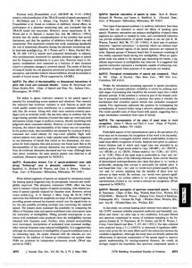
Fig. 1. The running crack subjected to concentrated point load.
D
2.2. Semi-infinite
Y
!!k
‘1ay
=--E
moving crack
Consider a semi-infinite crack located at Y = 0, X < 0 in an unbounded piezoelectric body (Fig. 1). It is assumed that the crack is in a static equilibrium state when t < 0 and its leading edge is parallel to the poling direction of the piezoelectric body. At t = Of, a pair of concentrated longitudinal shear forces is applied on the surface of the pre-existing semi-infinite crack and then the crack is assumed to propagate at a constant speed v. For dynamic fracture problems, it is usually convenient to study the crack propagation in a moving coordinate system (x, y, z), with x = X-vt,
y = Y,
In addition, we define the nondimensional
z = z.
(25)
parameter
s &% (1 - 02/c*)‘l2,
(26)
where c k (cJp>”
(27)
is the speed of the piezoelectrically stiffened bulk shear wave. By making use of (23, the equations of motion in the moving coordinate system are cast into the form
,azw
axw
2v
a*w
’ ax’+Q+Paxat
fY+!xo.
w
1 a%
2 at* - 0,
(28) (29)
As is customary in linear transient crack growth problems (Freund, 1990), we investigate the perturbation solution corresponding to transient loading of the existing and
Piezoelectric
1805
crack propagation-I
newly created crack faces, under the assumption that the pre-existing state is quiescent and can be removed by superposition. For such a solution, the remote boundary condition may be taken as 0,*(x, y, t) = 0 D&Y,
0=0
I + IYI
co.
(30)
Though different in origin, these conditions play a similar role to a wave radiation condition. Following the approach introduced by Freund (1972a), we take as the fundamental problem that of a concentrated crack face load with transient crack growth, so that the following mechanical boundary conditions are imposed c+(X,O, t) = -f?(x+?Jt)H(t) i W(X,0, t) = 0
x < 0
(31a)
x30
(31b)
where the antisymmetry of the loading and initial conditions has been used to introduce the second condition. In a purely elastic solid, the exact solution of the above problem may be straightforwardly obtained (Ma and Chen, 1992). The piezoelectric case is more complicated, with most of the difficulty stemming from the imposition of the electrical boundary conditions. 2.3. Electrical boundary conditions The issue of how to impose the electrical boundary conditions along the crack surfaces in piezoelectric fracture modeling is a controversial one (Suo et al., 1992 ; Pak, 1990). The difficulty is due both to the diversity of physical reality and to mathematical complications. McMeeking (1989b) has noted in the context of purely electrical loading that : If a closed slit is cut into a homogeneous dielectric, the opposing surfaces are still in contact. Consequently, the material is effectively seamless as far as an electrostatic field is concerned and the field will not be perturbed by the presence of the crack. Exceptions arise when the crack behaves as a conducting surface or is filled with a vanishingly thin medium which is impermeable to the electric field. So far, several electric boundary conditions on the crack surface have been proposed : effectively seamless slit (Parton, 1976) : c$’ = &, 0,’ = D; ; -impermeable void (Li et al., 1990; Pak, 1990) : 0,’ = D,; = 0; crack filled with conducting fluid (McMeeking, 1989a, b) : 4’ = &. Each of these assumptions provide useful analytical simplification, though there is not general agreement on their physical reasonableness, particularly in the case of a static finite crack. Moreover, these conditions appear to exclude some of the surface wave phenomena examined in our work, in particular those discussed in the vacuum
1806
S. LI and P. A. MATAGA
boundary condition case. Here we consider boundary conditions of the type dealt with in the electroacoustic literature (Bleustein, 1968 ; Gulyaev, 1969; Auld, 1973). Two kinds of electric surface conditions are usually considered. In the first case, the crack surface is assumed to be covered with a thin metal film with infinite conductivity, which shorts out the horizontal component of E at the crack surface but does not affect the mechanical boundary conditions. This metallized interpretation, which was elaborated by Bleustein (1968), is equivalent to assuming that the crack surfaces are coated with an infinitesimally thin, perfectly conducting electrode that is grounded, i.e. f#+,O+,t)
= &x,0-,t)
= 0
-cc
0
pm
- iN) Pm
(44) exp(Pmy)
Y < 0.
S. LI and P. A. MATAGA
1808
L 4m.w)
=
N3
ew(
-p/b)
Y>O
(45)
Pm - f
WI
exp(&)
y < 0.
:
The concentrated loading boundary condition dictates the choice m = 2, and the coefficient functions c( and b may be written as
(46) (47) Here E is introduced as an auxiliary (positive real) perturbation parameter, with the understanding that whenever E is present, the final expressions involved are always evaluated at E = 0 at the end of the manipulation. Remark 1. The technique of introducing an auxiliary parameter has been widely used in applying transform methods to solve partial differential equations (there are many useful examples in Duffy’s book (1994)). In particular, Broberg (1973) used the approach to facilitate the Wiener-Hopf decomposition that arose in his analysis of elastoplasto-dynamic crack growth. However, one may in fact motivate the “trick” for our present application by careful consideration of the quasi-static approximation implicit in the original governing equations. The basic hypotheses of the quasi-static approximation (Auld, 1973) are : first, the rotational electric field can be neglected ; second, all the electromechanical wave solutions travel at velocities compared to which the speed of electromagnetic waves, c,, is very large. From this point of view, it is physically plausible to write (43) as
d2 _ -P2(E2-12) dY2
1
pKY,P>
= 0,
where E is of order 0(1/c,). A detailed account from this perspective of the electromagneto-elastic equations in linear piezoelectric materials and the related SH mode electromagnetoacoustic surface wave has been carried out recently by one of the authors (Li, 1996) ; by taking into account the full Maxwell equations, a generalized wave speed equation for SH mode electromagnetoacoustic surface wave is derived, which reduces to Bleustein-Gulyaev wave when c/cr + 0. In (44) and (45), Re(cr([), /3(i)) 2 0 in the plane with branch cuts CI: Im([) = 0 j?:
Re([) < -l/(c-_y),
Im([) = 0
Re(i) < -E,
From the transformed electric boundary condition
and
Re(B) > l/(c+v),
(49)
and
Re([) > E.
(50)
Piezoelectric crack propagation-I
= 0,
-
1809
co) di
qlX,Y,P)
=
2
s
[g+im ” PW(I)
exp(-_pUb-C-4)
dL
(57)
i,,-1u
where the integration
paths are restricted - l/(c-u) -E
For displacement
and electrostatic
“*(x,Y,P)
by < [, < l/(c+zi),
(58)
----= Goo(4
J -v/co> (1
(1 +v/co)’
(159)
where
cg=
r
c44 -
(160)
P
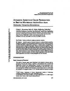
is the elastic shear wave speed. It is of interest to look at the preceding results from the point of view of a material with fixed elastic properties as piezoelectric coupling increases. Figure 7 shows the profiles of the normalized energy release rate at different values of k,, plotted against v/co. For v = 0 there is no effect of piezoelectricity on energy release rate; the result coincides with the elastic result for the same loading. There are two competing wavespeed effects : the bulk shear wave speed c increases with k, for fixed c,,, and the ratio cbg/c decreases with increasing k,. However, since Q,,/c, = 7 I+ k, , the former effect dominates, and the overall effect is to increase the energy release rate for a given crack speed and loading. Nevertheless, the Bleustein-Gulyaev wave speed provides for this case the limiting velocity for crack propagation, just as the Rayleigh wave does for the in-plane elastic case. For this reason, we have not in this paper discussed the supersonic crack velocity
1826
S. LI and P. A. MATAGA
Fig. 7. The normalized energy release rate C(ut, v)/G&ut) versus u/q
regimes for which u exceeds chg. This discussion is deferred until the second part of this work, in which we describe the much richer behavior arising when vacuum boundary conditions are applied.
ACKNOWLEDGEMENTS The work of the authors was partially supported by the Walter P. Murphy Fellowship from Northwestern University (SL), and by grant DMD-9057626 from the National Science Foundation (PAM). The comments, suggestions and literature references provided by the anonymous reviewers of an earlier draft of this paper are also gratefully acknowledged.
REFERENCES Achenbach, J. D. (1973) Wave Propagation in Elastic Solids. North-Holland, Amsterdam. Atkinson, C. and Eshelby, J. D. (1967) The flow of energy into the tip of a moving crack. Int. J. Fracture 4, 3-8. Auld, B. A. (1973) Acoustic Fields and Waves in Solids. John Wiley & Sons, New York. Baker, B. R. (1962) Dynamic stress created by a moving crack. J. Appl. Mech. 29,449%4X Bailey, T. and Hubbard, Jr, J. E. (1985) Distributed piezoelectric-polymer active vibration control of a cantilever beam. J. Guidance Control 8,605-6 Il. Berlincourt, D. A., Curran, D. R. and Jaffe, H. (1964) Piezoelectric and piezomagnetic materials
Piezoelectric crack propagation--l
1827
and their function in transducers. Physical Acoustics (ed. W. P. Mason), pp. 1699270. Academic Press, New York. Bleustein, J. L. (1968) A new surface wave in piezoelectric materials. Appl. Phys. Lett. 13,412413. Broberg, K. B. (1973) On dynamic crack propagation in elastic-plastic media. Proceedings af the International Conference on Dynamic Crack Propagation (ed. G. C. Sih), pp. 461499. Noordhoff International, Amsterdam. Cady, W. G. (1946) Piezoelectricity. McGraw-Hill, New York. Cagniard, L. (1939) Reflexion et Refraction des Ondes Seismiques Progressives. GauthierVillars, Paris. English translation Reflection and Refraction qfProgressive Seismic Waves, E. A. Flinn and C. H. Dix, 1962, McGraw-Hill, New York. Chen, P. J. (1983) Characterization of the three dimensional properties of poled PZT 65/35 in the absence of losses. Acta Mech. 47, 955106. Deeg, W. F. (1980) The analysis of dislocation, crack and inclusion problems in piezoelectric solids. Ph.D. thesis, Stanford University. de Hoop, A. T. (1960) A modification of Cagniard’s method for solving seismic pulse problems. Appl. Sci. Res. B 8, 349-360. Duffy, D. G. (1994) Transform Methods for Solving Partial Differential Equations. CRC Press, Ann Arbor. Eshelby, J. D. (1969) The starting of a crack. Physics of Strength and Plasticity (ed. A. S. Argon), pp. 263-275. MIT Press, Cambridge, MA. Freund, L. B. (1972) Crack propagation in an elastic solid subjected to general loading. I : constant rate of extension. J. Mech. Phys. Solids 20, 120-140. Freund, L. B. (1972) Energy flux into the tip of an extending crack in an elastic solid. J. Elasticity 2, 341-349. Freund, L. B. (1990) Dynamic Fracture Mechanics. Cambridge University Press, Cambridge. Gulyaev, Y. V. (1969) Electroacoustic surface waves in solids. Soviet Physics JETP 9, 37-38. Kostrov, B. V. (1966) Unsteady propagation of longitudinal shear cracks. J. Appl. Math. Mech. 30, 1241-1248. Original paper in Russian is in Prikladnaia Matematika I Mekhanika 30, 1042~1049. Li, S., Cao, W. and Cross, L. E. (1990) Stress and electric displacement distribution near Griffith’s type III crack tips in piezoceramics. Mater. Lett. 10, 219-222. Li, S. (1996) The electromagneto-acoustic surface wave in a piezoelectric medium : the Bleustein-Gulyaev mode, to appear in J. Appl. Phys. Ma, C.-C. and Chen, S.-K. (1992) Investigation on the stress intensity factor field for unstable dynamic crack growth. Int. J. Fracture 58, 345-359. McMeeking, R. M. (1989) Electrostrictive stress near crack-like flaws. Zeitschrtft fur An,qewandte Mathematik und Physik 40, 6 1S-627. McMeeking, R. M. (1989) On mechanical stresses at cracks in dielectrics with application to dielectric breakdown. J. Appl. Phys. 62, 31163122. McMeeking, R. M. (1990) A J-integral for the analysis of electrically induced mechanical stress at cracks in elastic dielectrics. Znt. J. Engng Sci. 28, 605613. Maugin, G. A. (1983) Elastic surface waves with transverse horizontal polarization. Advances in Applied Mechanics (ed. C. S. Yih), Vol. 23, pp. 373434. Academic Press, New York. Maugin, G. A. (1993) Material Inhomogenieties in Elasticity. Chapman & Hall, London. Maugin, G. A. (1994) On the J-integral and energy-release rate in dynamical fracture. Acta Mech. 105, 3347. Noble, B. (1958) Methods Based on the Wiener-Hopf Technique. Pergamon Press, New York. Pak, Y. E. (1990) Crack extension force in a piezoelectric material. J. Appl. Mech. 57, 6477653. Pak, Y. E. (1992) Circular inclusion problem in antiplane piezoelectricity. Znt. J. Solids Struct. 29,2403-24 19. Pak, Y. E. (1992) Linear electro+lastic fracture mechanics of piezoelectric materials. Int. J. Fracture 54, 799100. Parton, V. Z. (1976) Fracture mechanics of piezoelectric materials. Acta Astronautica 3, 671683.
1828
S. LI and P. A. MATAGA
Parton, V. Z. and Kudryatvsev, B. A. (1988) Electromagnetoelasticity. Gordon and Breach, New York. Pohanka, R. C. and Smith, P. L. (1988) Recent advances in piezoelectric ceramics. Electronic Ceramics (ed. L. M. Levinson). Marcel Dekker, New York. Rao, S. S. and Sunar, M. (1994) Piezoelectricity and its use in disturbance sensing and control of flexible structures : a survey. Appl. Mech. Rev. 47, 1133123. Sih, G. C. and Chen, E. P. (1977) Cracks moving at constant velocity and acceleration. Mechanics of Fracture 4 : Elastodynamic Crack Problems (ed. G. C. Sih), pp. 59-117. Noordhoff, Amsterdam. Sosa, H. A. (1990) Three-dimensional eigenfunction analysis of a crack in a piezoelectric material. Znt. J. Solids Struct. 26, l-15. Sosa, H. A. (1991) Plane problems in piezoelectric media with defects. ht. J. Solids Struct. 28, 491-505.
Sosa, H. A. (1992) On the fracture mechanics of piezoelectric solids. Int. J. Solids Struct. 29, 2613-2622. Suo, Z., Kuo, C.-M., Barnett, D. M. and Willis, J. R. (1992) Fracture mechanics for piezoelectric ceramics. J. Mech. Phys. Solids, 40, 739-765. Suo, Z. (1993) Models for breakdown-resistant dielectric and ferroelectric ceramics. J. Mech. Phys. Solids 41, 1155-l 176. Tiersten, H. F. (1969) Linear Piezoelectric Plate Vibrations. Plenum Press, New York. van der Pal, B. and Bremer, H. (1955) Operational Calculus, 2nd edn. Cambridge University
Press, Cambridge. Viktorov, I. A. (1981) Surface Sound Waves in Solids. Nauka, Moscow (in Russian). Wang, B. (1992) Three-dimensional analysis of a flat elliptical crack in a piezoelectric material. Znt. J. Engng Sci. 30, 781-791.
Zhang, T.-Y. and Hack, J. E. (1992) Mode-III crack in piezoelectric materials. J. Appl. Phys. 71,5865-5870.
APPENDIX
A : PRODUCT
DECOMPOSITION
OF S(5)
This appendix outlines the derivation of the product decomposition of an expression involving the Bleustein-Gulyaev function cc([)- kafi( y+ > --E
(A.3)
I829
Piezoelectric crack propagation-I -dz,
Since in the present
work we restrict attention
.s*-k,4
=
=
(A.5)
to cases where ~1< cbg
+p)(cbr+u)>0.
A polar decomposition may now be employed along branch cuts in P_(i) are as follows
argS(i)
Re([) < y_ < E.
to advantage.
64.6)
The argument
f arctan (Z(y>
(A.9)
(c)
Cauchy’s integral theorem and [A.~(c)] and [A.~(c)] allow the rewriting the following contour integrals logS+(5)
(b)
--E
of (A.4) and (A.5) as
(A.10)
and log S (i) = & s r+
log S(z) d z, ~ z-i
Re([) < :’ < E,
(A.1 1)
where integration contours f+ are shown in Fig. A.1, and both f’+ and f.. traverse in the clockwise direction. From Fig. A. 1, one can see that there are three branch points along each integration contour ; this differs from the decomposition of the Rayleigh wave function used in in-plane mode crack propagation in an elastic medium (Achenbach, 1973), for which there are only two branch points along each integration contour. Now we proceed to evaluate the contour integral for S+(c). Since ]S(q+iO’)] = ]S(q+iO -)I. it follows by direct (but nontrivial) application of the residue theorem that (A.12)
Consequently,
1830
S. LI and P. A. MATAGA
A Irnd)
c - Plane
Red) c l/(cbg
-t- v)
Fig. A. 1. Integration contours used for product decomposition of function S(c).
logS+([)
= f
- 1!&,-“) drl v-i s -,K-“,
(*.,3)
so that
(A. 14) where k&/m
Z(q) A s
(A. 15)
(l/(c-~)+ll)(l/(c+u)-rl)
Similarly,
S_(i)
= Jzexp{-i[“““_tan(E(q))3).
Finally, letting E --t 0 in (A. 14)-(A. 16) yields (82), (83) and (84).
(A.16)