transmit power level and the data rate jointly to the radio channel conditions. ... possible data rate and adjust the rate and power levels accordingly ...
International Journal of Wireless Information Networks, Vol. 12, No. 3, July 2005 (� 2005) DOI: 10.1007/s10776-005-0006-x
Dynamic Data Rate and Transmit Power Adjustment in IEEE 802.11 Wireless LANs Pierre Chevillat,1 Jens Jelitto,1,2 and Hong Linh Truong1
In this paper a novel link adaptation algorithm is proposed that is capable of adjusting the transmit power level and the data rate jointly to the radio channel conditions. The proposed method relies solely on link quality information available at the transmitter by employing the reception or non-reception of the acknowledgment frames as a measure of the channel quality with respect to the power level and data rate. The method is fully compatible with the 802.11 wireless LAN standard. In contrast to many other proposals, it neither relies on the RTS/CTS protocol nor requires a feedback channel to transmit link-quality estimates from the receiver to the transmitter. Different strategies for optimizing the data rate and power level are given. These depend on the scenarios considered, the number of active stations, and the service requirements. The two main strategies are either to drive the system towards the highest possible data rate and adjust the rate and power levels accordingly (‘‘high-performance’’ mode) or to focus on power saving, possibly trading this for other performance criteria such as throughput or delay performance (‘‘low-power’’ mode). Other special cases, such as power or rate only adaptation, are also discussed. It can be shown that in most cases the best choice for achieving low transfer times, maximizing throughput, and alleviating the hidden terminal problem is to transmit at the highest possible rates and with high power levels. This ‘‘highperformance’’ mode of operation also minimizes the transmission times, which in turn maximizes the time for putting idling components into a sleep mode, thereby minimizing the overall power consumption. KEY WORDS: 802.11 Wireless LANs (WLANs); dynamic link adaptation; power and rate adaptation; throughput optimization; power efficiency.
1. INTRODUCTION
many cases. However, if the distance to the receiver is long, using a high data rate may lead to an excessive number of retransmissions owing to the low signalto-noise ratio (SNR). This may result in performance degradation or even in a total loss of communication. In such a situation, a more robust but lower data rate may achieve a better throughput. Other parameters that affect overall system performance also need to be considered. For battery-powered devices such as laptops and PDAs, transmission power awareness is crucial to save energy and prolong battery life. Reducing the transmit power level, in particular when the distance to the receiver is small, also helps reduce interference with neighboring WLANs. To achieve the highest possible system performance, it is
Broadband wireless LANs (WLANs) based on the IEEE 802.11a [1] and 802.11g [2] physical layer standards support multiple data rates, which enables wireless stations (WSTAs) to select the appropriate transmission rate depending on the required quality of service and the radio channel conditions. To maximize the throughput or minimize the transmission delay, using a high data rate is the right choice in 1
2
Zurich Research Laboratory, IBM Research GmbH, Sa¨umerstr. 4/Postfach, CH-8803 Ru¨schlikon, Switzerland. Tel.: +41-1-724-84-96; Fax: +41-1-724-89-55; E-mail: jje@ zurich.ibm.com
123 1068-9605/05/0700-0123/0 � 2005 Springer Science+Business Media, Inc.
124 therefore mandatory to use an automatic link adaptation algorithm that allows a station to adapt its transmission parameters to the actual conditions of the wireless channel. The interest in designing a link adaptation mechanism for 802.11 WLANs is large because the basic 802.11 MAC standard [3] does not specify any procedure for rate switching or power level selection. Many papers have appeared on this topic, most of them only dealt with either rate adaptation [4–11] or transmit power control [12–15]. A few papers described algorithms that combine rate adaptation with power control [16–18]. The classical way of performing link adaptation is to rely on feedback from the receiver. In this approach the channel quality is estimated from the SNR, the received signal strength, or packet error rate measurements, and the transmit rate or power level to be used in future transmissions is derived. This information is then sent back to the transmitter over a feedback channel [19,20]. Unfortunately, the 802.11 MAC standard does not provide any protocol means for the receiver to inform the transmitter about the link quality or the transmission rate to be used. Link adaptation methods relying on a feedback channel therefore cannot be employed or require a modification of the 802.11 standard. A number of algorithms proposed make use of the so-called ‘‘RTS/CTS’’ protocol to exchange the information needed for the adaptation. The RTS/ CTS protocol is defined in the 802.11 standard to combat the well-known ‘‘hidden’’ terminal problem. Before sending a data frame, a transmitting station makes a reservation for the wireless channel by sending a short ‘‘Ready-To-Send’’ (RTS) frame. The receiving station replies with a ‘‘Clear-To-Send’’ (CTS) frame. The transmitting station proceeds with the transmission of the data frame after having received the CTS frame. All other stations in the vicinity of the transmitter and the receiver that have received these two frames will defer their own transmissions until the end of the reservation. Thus, the RTS/CTS protocol can be exploited to exchange link adaptation parameters such as rate and packet size [4], or interference margins and transmit power levels [12]. An interesting idea is described in [9], in which the access point (AP) broadcasts special beacon frames that allow the wireless stations (WSTAs) to detect their locations relative to the AP and to determine the transmit rates to be used.
Chevillat, Jelitto, and Truong Another alternative is to measure the received signal strength and derive the transmit parameters from that measurement [11,21]. The transmit power level can also be included in the packets, such as in the method described in [17], in which a combined rate and power adaptation for 802.11a WLANs operating under the Point Coordination Function (PCF) is described. The main idea is to include the information about the transmit power level in the SERVICE field of a MAC frame that is sent by the Point Controller (PC). This information will allow the receiver of the frame to estimate the path loss between itself and the PC, and to determine the best rate–power pair to be used for future transmissions. A similar method is defined in [18] for the 802.11 Distributed Coordination Function (DCF). It uses the RTS/CTS frames sent at full power prior to any data transmission to estimate the path loss. The WSTAs determine the best power–rate combination from a table indexed by the packet length, the path loss condition, and the retry counters of the DCF procedure. The table entries are calculated off-line. All algorithms described so far require either a modification of the 802.11 standard or the cooperation of the peer station, e.g. when making use of the RTS/CTS procedure. These drawbacks can be avoided by employing only information that is available at the transmitter. In [5], the transmitter switches between two fixed data rates, with the higher rate being the default operating mode. After two consecutive transmission errors, it uses the lower rate, and returns to the high one after 10 successful transmissions or after a time out. This technique was enhanced in [10] to handle multiple transmission rates and varying channel conditions. In [22] the mechanism of [10] is employed to adapt the transmit power levels to the channel conditions; however, the transmission rate is maintained at a fixed value. In this paper we extend the ideas proposed in [10] and [22] to a new link adaptation algorithm that is capable of adjusting jointly the transmit power level and the data rate to the radio channel conditions. The method is fully compatible with the 802.11 wireless LAN standard. It neither relies on the RTS/ CTS protocol nor requires a feedback channel to transmit link-quality estimates from the receiver to the transmitter. Instead, the proposed scheme relies solely on information available at the transmitter by using the ACK frames. In the next section we will discuss some fundamental link adaptation issues. In Section 3 the proposed joint power and rate adaptation
Dynamic Data Rate and Transmit Power Adjustment in Wireless LANs algorithm is presented. A comprehensive evaluation of the performance of the proposed scheme is given in Section 4. Finally, Section 5 concludes the paper.
2. LINK ADAPTATION PRINCIPLES Our goal is to optimize the throughput and transmit power for a given channel, i.e., to transmit as many bits with as little energy as possible. The optimization strategy depends on several factors, such as the service requirements (e.g. target data rate, delay constraints), power consumption, and battery lifetime, but also on coexistence and fairness considerations in a wireless network. The parameters that can be controlled by a link adaptation algorithm are the transmit power PD, the data rate rD, and the packet length lD. Although the throughput depends also on the packet length [23], it has been shown in [22] that fragmenting large packets as defined in the 802.11 MAC standard [3] is not an appropriate means for increasing throughput because every fragment is acknowledged separately. Hence, the overhead increases linearly with the number of fragments. For this reason, only transmit power and data rate adaptation will be considered in this paper. Let us define the effective throughput of a WLAN as TP ¼
Nb ; T
ð1Þ
where Nb is the total number of successfully transmitted data bits in the observed time interval T. The time interval T includes the transmit times TD of the data packets and overhead times TOH such as DIFS (Distributed Interframe Space), SIFS (Short Interframe Space), acknowledgment times, backoff times and other idle times (e.g. waiting times for new packets in a system that is not in saturation). In addition, let us define the average transmit power as P PK�1 PD;k TD;k þ L�1 l¼0 POH;l TOH;l P�tx ¼ k¼0 ; ð2Þ T where PD;k is the transmit power of the kth data frame transmitted, TD;k the transmit time of the kth data frame, and K the total number of data frames transmitted, including erroneous frames. POH;l is the power associated with the lth overhead time TOH;l (e.g. to transmit an ACK frame, or the power consumed during idle times DIFS, SIFS), and L the total number of overhead events. In the simulation results presented in the next section, the power consumed
125
during idle times (e.g. DIFS, SIFS) is not considered and set to zero. Hence, as long as no RTS/CTS mechanism is enabled in the system, the overhead energy consumption is determined by the transmission power PA and transmission time TA of the ACK frames to acknowledge successful data transmissions. Note that even in this case, K and L are not equal because of unsuccessful transmission attempts. From these two definitions the power efficiency can be derived as TP Nb gTP ¼ � ¼ PK�1 : PL�1 Ptx k¼0 PD;k TD;k þ l¼0 POH;l TOH;l ð3Þ The denominator describes the overall transmit energy consumption associated with the successful delivery of Nb data bits. To maximize the power efficiency, the times TD and TOH and the powers PD and POH should be kept as small as possible for the given service requirements. The transmission times TD(lD,rD) and TA(lA,rA) depend on the frame lengths lD and lA and the transmission rates rD and rA of the data and ACK frames, respectively. For 802.11a, the time to transmit a data frame of lD bytes at rate rD is [1] � � 16 þ 8 � lD þ 6 TD ðlD ; rD Þ ¼ TPA þ TSIG þ TSYM � ; NDBPS ðrD Þ ð4Þ where TPA, TSIG and TSYM are the times to transmit the preamble, the signal field and one OFDM symbol of the 802.11a OFDM PHY layer, respectively. NDBPS is the number of data bits encoded within one OFDM symbol and depends on rD. The operator d e returns the smallest integer value greater than or equal to its argument value. In 802.11a, these parameters have the values TPA=16 ls, TSIG= TSYM=4 ls, NDBPS=4Æ rD. Possible transmission rates are rD=6, 9, 12, 18, 24, 36, 48, and 54 Mbps. If we assume a packet length of lD=1000 bytes, the transmission times for the different data rates are TD(lD=1000 bytes, rD ={6,9,12,18,24,36,48,54} Mbps)={1360,912,692,468,356,244,188,172} ls. Hence, for lD=1000 bytes, the transmission time at a rate of 54 Mbps is approximately 1/8 of the time required at a rate of 6 Mbps. The transmit power necessary for a certain service requirement depends on the transmission rate, the distance between communicating devices, the channel characteristics and other factors; there exists no simple relationship. Assuming a fixed
126
Chevillat, Jelitto, and Truong
10
10
0
6 Mbps
–1
6 Mbps 9 Mbps 12 Mbps 18 Mbps 24 Mbps 36 Mbps 48 Mbps 54 Mbps
24 Mbps 12 Mbps 9 Mbps
AWGN
Packet Error Rate
18 Mbps
ETSI ’A’ 36 Mbps 48 Mbps 54 Mbps
10
–2
18 Mbps
6 Mbps 12 Mbps
10
–3
24 Mbps
36 Mbps
48 Mbps 9 Mbps 54 Mbps –4
10
–2
0
2
4
6
8
10
12
14
16 18 E /N
20
22
24
26
28
30
32
34
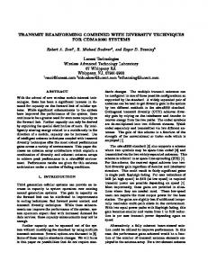
Fig. 1. Packet error rate as function of Es/N0 and the 802.11a data rates for AWGN (solid) and ETSI ‘‘A’’ (dashed) channel (18 taps, Rayleigh fading, rrms=50 ns, rmax=400 ns).
distance between transmitter and receiver, a rough estimate of the relative transmit power requirement as a function of the transmission rate to support a desired packet error rate (PER) can be extracted from Figure 1. For an AWGN channel and a desired PER of 10)2, let the necessary transmit power be PD(rD=6 Mbps)=P0. The power levels required for the different rates are roughly PD(rD={6,9,12,18,24,36, 48,54} Mbps)={1,2,2,4,8,16,32,64}Æ P0. Hence, a power difference of about 18 dB, or 64 times the power level, is required to maintain the same PER at a rate of 54 Mbps as at 6 Mbps. This power ratio of 18 dB is also confirmed by [24]. The transmit rates rA for the ACK frames are defined by the standard, hence the times TA are given. As the immediate ACK procedure and its reliability are crucial for the system, it is assumed that all ACK frames are transmitted at the highest power level.
From the above results, several observations can be made. If the transmit power is fixed, one should try to transmit at the highest possible rate. This increases the power efficiency and minimizes the air time. This in turn increases the system throughput and minimizes the collision probability. If, on the other hand, the rate is fixed (as might be required by a service), the lowest possible power level should be used to save energy. However, this strategy might worsen the hidden terminal problem. If both the transmit power and data rate are adaptive, the comparison of the transmit time ratio (1/8) and the transmit power ratio (64/1) for 54 and 6 Mbps suggests to transmit at the lowest possible data rate and then optimize the transmit power accordingly. However this statement is only valid if we consider the power efficiency for a single communication link. There are several issues that need to be taken into account:
Dynamic Data Rate and Transmit Power Adjustment in Wireless LANs
• The power efficiency does not take into account the energy consumption of the baseband and MAC layer signal processing. Higher data rates allow the radio front-ends as well as the PHY and MAC engines to be put into an energy-saving sleep mode for longer time periods. • The reduced transfer times associated with higher data rates result in a reduced collision probability. This will result in a reduced retransmission rate and better throughput performance than for a low data rate transmission. • Higher power levels associated with higher data rates lead to a less pronounced hidden terminal problem, as more stations can ‘‘hear" a station transmitting at a higher power level. • To optimize the aggregate throughput in a cell, the best strategy is to use the highest possible data rates for data transmission. • The transfer times depend on the data rate, backoff times, and retransmissions needed. Hence, as long as higher data rates do not considerably increase the retransmission probability, using the highest possible data rates will result in the shortest transfer times. The arguments given above suggest that the best strategy is to select the highest possible data rate and adjust the transmit power accordingly.
3. JOINT POWER AND DATA RATE ADAPTATION 3.1. Proposed Algorithm The link adaptation algorithm proposed here makes use of the immediate ACK strategy defined in the IEEE 802.11 MAC protocol [3]. Error-free data frames are immediately acknowledged by the receiver. Frames are protected against errors (due to transmission errors or collisions) by means of a frame check sequence (FCS) field containing a 32-bit cyclic redundancy code (CRC) and a simple send-and-wait ARQ mechanism. If the receiver detects a CRC error the frame is discarded. Otherwise, the receiver sends an ACK frame back to the transmitter. If no ACK frame is received within a specified time, the frame is re-sent after a random back-off time. This process is repeated until the transmitter receives an ACK, a packet lifetime value is exceeded, or a maximum
127
number of retries has been reached. In the latter two cases, the transmitter discards the frame. As no channel state information (CSI) is available at the transmitter, the proposed algorithm exploits the ability of the immediate ACK procedure to detect frame loss. If the transmitter does not receive an ACK within a specified time interval, the algorithm concludes that link quality was insufficient and that a lower data rate or a higher transmit power should be used. On the other hand, if the transmitter succeeds in sending multiple data frames, it assumes that the link quality is sufficient and that a higher rate or a lower transmit power can be used. This adaptation scheme can be implemented in the transmitter with a pair of counters for every destination MAC address: one for successful transmissions s and one for failed transmissions f. If a frame is successfully transmitted, counter s is incremented and counter f reset to zero; similarly, if a transmission fails, counter f is incremented and counter s reset. If the success counter s reaches a certain threshold Smax, then the data rate is increased or the power decreased, and both counters are reset to zero. Similarly, if the failure counter f reaches a certain threshold Fmax, then the data rate is decreased or the power increased, and both counters are reset to zero. 3.2. Dynamic Threshold Adaptation The values of Fmax and Smax are critical for the performance of the link adaptation scheme [10]. Throughout the paper we assume that Fmax=1. This conservative choice corresponds to an immediate adaptation towards a more robust operating point by decreasing the data rate and/or increasing the power in the case of a failed transmission. This strategy prevents unnecessary retransmissions at the price of a slightly suboptimal steady-state performance. The optimum choice for Smax depends on the channel dynamics. Fast-changing channels require a small value of Smax, so that the transmission parameters can keep up with the channel variations. On the other hand, for slowly changing channels, large values of Smax avoid ineffective switching to higher rates or lower power levels when the channel has not improved. Exploiting these observations, the basic algorithm described in Section 3.1 is enhanced with a simple but powerful method that estimates the speed of link-quality variations and switches dynamically between two success threshold values, namely S1 and
128
Chevillat, Jelitto, and Truong
Fig. 2. Transition diagram of the link adaptation algorithm.
S2, with S1