Dynamic Fuzzy Controller Based Multilayered Architecture for Extended Battery Life in Mobile Handheld Devices Tamanna Srivastava
Apurva Narayan
Dayalbagh Educational Institute Deptt. of Physics and Computer Science Pune, India
[email protected]
Schlumberger Oilfield Services Pune, India
[email protected]
Abstract—Recently, the mobile phones are evolving into mobile multifunctional terminals with the incorporation of various useful functions; the display devices also have advanced in terms of size, design, and resolution as a user interface of the mobile phone. Many low power display techniques have been proposed for example Dynamic Luminance Scaling, Liquid Crystal Orientation Shift, Variable Frame Refresh, Organic LEDs (Light Emitting Diodes) etc. It has been observed that optimizing software alone or hardware alone the solution might not be most optimal. The paper describes the design of a Dynamic Fuzzy Controller Based Multilayered Architecture which is a combination of software and hardware levels to interface between software application layer and physical layer to eventually control the current through LEDs of cell phone and thereby improving battery life depending on user choices and applications running on mobile devices. Index Terms—Fuzzy Controller, Cellphone Display, multilayered architecture
I. I NTRODUCTION The next generation mobile system. 3G technologies enable network operators to offer users a wider range of more advanced services such as wide-area wireless voice telephony, video calls, and broadband wireless data, all in a mobile environment. This necessitates the associated interfaces also to advance along with the next generation mobile system. The mobile phone has become as indispensable like many other products making this a necessity for additional features in the phone. All battery operated mobile embedded systems have limited power available and all interfaces consume battery of cell phone. Need for processing intensive applications combined with better multimedia application has increased the demand for more power from battery, reducing battery life significantly. Extending battery life and sustaining an ever increasing demand for more applications has opened a new field for research. Both at university and industry significant research work has been taken up to improve battery life. The display interface which is typically the LCD display of cell phone consumes maximum power and hence the battery life depends mostly on it as compared to other interfaces. Many low power display techniques which are limited to physical layer have been introduced which will be discussed in brief in section 3. Section 2 discusses about LCD display interface and its various features. In this paper we propose the design of back light controller which is the combination of hardware and software level using fuzzy logic to optimize the power
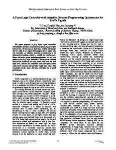
consumption, described in section 4. Section 5 discusses about the simulation and hardware implementation of the proposed controller. The controller is designed in such a way that depending on user’s input and application based cell phone settings, the intensity of white LEDs will be controlled which will be overridden by the fuzzy controller up to a certain extent based on available battery and the ambient light. Fuzzy logic eventually helps user to decide on brightness of the display. Section 6 gives the conclusion of the work done. II. LCD D ISPLAY I NTERFACE Today even cell phones are equipped with colour thinfilm transistor (TFT) liquid crystal displays (LCDs) [1]. A LCD system is now the default configuration for handheld mobile systems. An LCD panel needs light source in order to illuminate itself. A transmissive LCD uses a backlight source, which consumes maximum power among all system components. A reflective LCD uses ambient light and a reflector to reflect light from external light sources. Since reflective LCD is not suitable for quality displays, and hence transflective LCD that reflects and transmits light, is used for small hand-held devices. Even transflective screens also need backlight [2]. Major sources of power dissipation in a portable electronic device vary as a function of the device functionality and performance specification. Currently cold cathode fluorescent lamp (CCFL) and a white light emitting diode (LED) are the most popular choices for TFT LCDs. A white LED backlight circuit is used in mobile displays. The power consumption of the backlight ranges from 0.4 to 4W, which is 20% to 30% of the total system power. For a typical multimedia application the power distribution among all the components of display system is shown below as described by [3]. Among the sources of power consumption, the display backlight is the single largest power consumer in a typical LCD module as depicted in Fig. 1. Unlike the other system resources, it is difficult to tackle this power thirsty component with some form of power shutdown. Thus, reducing power consumption by backlight is one of the primary ways to extend battery life in battery-powered mobile devices. Existing power reduction techniques are based on power management during idle times, and are therefore difficult to apply to display panels which do not have idle time as long as they are turned on.
Fig. 1.
Power Distibution among various components of a Cellphone
III. L OW P OWER D ISPLAY T ECHNIQUES Despite the limited power available in a battery-operated mobile system, the display is required to have sufficient resolution and colour depth to support graphical user interfaces and multimedia applications. High-resolution, high-colour LCDs require large LCD panels, high-wattage backlight lamps and large-capacity frame buffer memories, which together lead to high power consumption. The CPU and the memory are in low power mode during the idle time, but the display components are always in active mode, for as long as the display is turned on. This makes the LCD backlight which is white LEDs in mobile displays, the dominant power consumer compared to other components. In this section, we summarize some of low-power display techniques for display systems. ”Dynamic backlight luminance scaling” (DLS) as explained in [4] keeps the intensity or contrast of the image as close as possible to the original while achieving significant power reduction. DLS compromises quality of image over power consumption, which fulfils a large variety of user preferences in computationally intensive applications. DLS saves 20% to 80% of power consumption of the backlight systems while keeping a reasonable amount of image quality degradation. ”Variable dot clock,” [5] slows down the screen’s refresh frequency to the lowest frequency for a given purpose, while keeping the flicker down to a minimum. Since every component in the display system is slowed down, power consumption can be reduced by 28.1% to 37.0%. ”Variable frame refresh,” [5] which uses the fact that liquid crystals can maintain their current orientation while their stored capacitance is discharged. Therefore by suspending the communications between different LCD components when the image remains constant, and allowing the LCD display system to shutdown, 23.6% to 31% savings in power can be achieved. ”Liquid crystal orientation shift,” [5], provides additional power savings by reducing the clarity of the image in areas of the screen that are not currently in focus. Since it is known that ”power consumption is positively correlated with the amount of charge that must be stored in the display matrix capacitors,” by using the default, unpolarized state of liquid crystals, energy consumption is minimized. Therefore, areas which are not in focus can be set to the colour of unpolarized state. The fourth technique proposed by the authors [5] suggests that ”backlight autoregulation” could produce significant
power savings of up to 60.2% using hardware sensor embedded on LCD module. The drawback is that this method is only applicable when there is a high contrast, as reducing the backlight reduces visibility of the image. ”Variable-duty-ratio refresh,” [6] is similar to ”dot-clock frequency”. Since one of the properties of LCDs is that they flicker only when the refresh rate is slower than the time constant of the storage capacitors, so the refresh rate can be reduced as long as the time constant is smaller than that of the storage capacitors. This method saves energy throughout the frame buffer, yielding an approximate 19% savings in energy. ”Dynamic-colour-depth control,” [6] reduces the LCD’s colour depth and alters the pixel organization to reduce power by shutting down unused video memory. ”Organic LEDs” [3] is the new concept in display technologies. Organic LEDs are a mix of LCD + back light, therefore technology with OLED does not need a special back light, this itself emits light and also does colour filtering. It is a simple matrix of a light source and a pixel matrix which can be independently turned off or on hence no additional matrix to control is required and hence consumes less power which can be as low as 60% of the original LED system. But OLEDs have low life span, almost 20% of White LED system [7]. Each of the above techniques saves the power consumption of the display system by reducing the activity of the corresponding LCD system components like the backlight luminance, the colour depth, the refresh duty ratio, and the pixel brightness. Organic LEDs are also used in mobile phones for low power consumption with low life span. Till now power improvement has been done at hardware level not at software application part. Hypothesis is that when we optimize the hardware alone or the software alone, the solution is not necessarily the most optimized one. Hence, an option of taking combination of both hardware and software needs to be addressed. IV. C OMBINATION OF H ARDWARE AND S OFTWARE BASED D ISPLAY T ECHNIQUE USING F UZZY L OGIC We propose to design an interface between application layer and physical layer and control the LED (backlight) output through LED controller which takes input from different blocks like Fuzzy Controller, user input, memory, housekeeping processor. The controller will be designed in such a way that the LED output will be dependent on battery life, ambient light through fuzzy controller as well as application layer and the user’s choice based on specific application. There are many instances where bright display is not needed for current application running on cell phone. We propose here that using multi-layer, which are, user layer, application layer and physical layer, cross functional interface system might be more optimal. By having user defined display setup, the increased battery life can be evaluated from a conventional standard setup in which display time, intensity and colour spectrum does not vary with application. We offer some options in cell phone which can be chosen by the cell phone user depending on the application running on the system. For this purpose
we had conducted a survey to understand whether the mobile users also agree to this proposal and we found that there are many applications in cell phone where users do not need the display with maximum intensity. Hence without changing the hardware technology used by the mobile phone, battery life can be optimized only by controlling the current through the backlight LEDs and number of LEDs to be switched on for a particular application. The existing design is to control backlight LEDs using hardware level techniques like DLS, liquid crystal orientation shift (LCOS), Backlight Autoregulation (AR), Variable Frame Refresh (VFR), Organic LEDs (OLED) etc. We propose a new design which takes multi domain/ multi layer inputs combined with existing hardware techniques and controls the current/ voltage through LEDs to have variable brightness. We denote the current architecture with help of a simple linear graph as shown in Fig. 2. We further also explain the new architecture which uses multi domain and multi layered inputs using a linear graph which makes the system easier to understand as shown in Fig. 3.
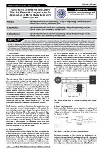
We investigate the option of taking input from different layers of the protocol stack and user inputs to optimize the duration of current through the LED thereby improving the battery life. The block diagram of proposed architecture is given below in Fig. 4. Use of fuzzy controller makes the controller to work more efficiently and override the user inputs and application layer inputs in some special cases. Explanation of each block is given.
Fig. 4.
Block diagram of the multilayered cross functional system
A. Application Based Controller Fig. 2.
Fig. 3.
Existing Linear Graph Representation
New Linear Graph Representation for multilayered architecture
The controller takes input from protocol stack to get the application level information, specifically to find the current application running on the cell phone which could be SMS, Call Placed, Call Received, Music, Games or any other application. These inputs can be received from House Keeping processor which monitors different blocks of cell phone to find which is currently active for a particular application. Controller also takes inputs from user which can be changed at run time. We offer user to change the brightness, colour of display (white or blue), display off time depending on the application running. Controller also interfaces with the memory block of cell phone which stores the mode setting of cell phone, which could be either power mode (low intensity), balance mode (medium intensity), high performance mode (high intensity). All these inputs are combined and processed depending on the priority level. User inputs have highest priority; it will override all other inputs. If user has not changed anything then depending on mode setting and application layer inputs; display off time, intensity level of LEDs and number of LEDs to be switched on will be decided using the various control units.
B. Fuzzy Controller This is an important block of the design, which takes care of intensity level when user has not decided on mode settings. The fuzzy controller takes input values from the real world. These values are referred to as ”crisp” values since they are represented as a single number, not a fuzzy one. In order for the fuzzy controller to understand the inputs, the crisp input has to be converted to a fuzzy identifier. This process is called fuzzification. The next step in the fuzzy control process is the implementation of the rule base. This is where the fuzzy inputs are compared and based on the membership of each, the fuzzy output is chosen. For a 2 input system with 3 membership functions for each input, there are 9 fuzzy rules to compute. The final step is to convert the fuzzy outputs of the rule-base to crisp ones. This process is known as defuzzification. This process will take a fuzzy number and apply it to a membership function to achieve the crisp number that will be sent to the external device. Therefore based on battery life and ambient light the intensity level of LEDs will be given as output. There are 3 parts to a fuzzy controller, the fuzzification of the inputs, the rule-base application to obtain the output sets and the defuzzification of the outputs. 1) F uzzif ication:The 3 membership functions are reassigned the linguistic labels of high, medium and low. The fuzzy controller uses overlapping membership functions for the inputs. For low values, membership functions High, Medium, Low are non overlapping but for values in Medium and High range, membership functions are overlapping as described below. All values of battery life and ambient light are in the range 0 and 255. By applying some offsets, these values have been brought under range (-192,64). These new values are being fuzzified as follows • Low Region −64 ≤ X < 0 TABLE I L OW R EGION Label Low Medium High
•
255 0 0
Medium Region −192 ≤ X < −64 a) −192 ≤ X < −128 TABLE II M EDIUM R EGION -A Label Low Medium High
TABLE III M EDIUM R EGION -B Label Low Medium High
•
0 255−(255∗(X+128)) 64
255-Medium
High Region 0 ≤ X < 64 TABLE IV H IGH R EGION Label Low Medium High
0 255-High X 255 ∗ 64
Real data coming from battery life sensor and real time ambient light sensor is first digitized using 8 bit Analog to Digital Convertor. These inputs are fed to fuzzy controller which is fuzzified using membership functions. Range of membership functions is given in table below in Table. V: TABLE V L INGUISTIC M ODIFIERS Label Low Medium High
Low Value 0 64 192
High Value 64 192 255
One of these labels is assigned to incoming value depending on the range in which it falls. This gives us the fuzzified value of battery life and ambient light 2) F uzzyRuleBase: The rule-base is implemented with a two input, one output systems. All the inputs use the same linguistic modifiers of high, medium, low. Based on the linguistics, 9 rules were established and outputs were chosen based on the desired output for the system. For example in case of low battery life and high ambient light the output intensity level can be adjusted to have lower value which could be fuzzified to a low label. The 9 rule distribution is shown below in Table. VI. This returns three fuzzified values of low, medium, high based on following rules: a) B = Battery Life b) A = Ambient Light
255-Medium 255+(255∗(X+128)) 64
b) −128 ≤ X < −64
0
TABLE VI RULE BASE I: S YMMETRIC FUZZY RULE BASE OF 9 FUZZY RULES BatteryLif e
AmbientLight
L M H
L M M
L L L
V. S IMULATION AND R EAL T IME E XPERIMENTS Low Value • Low = min(Blow , Alow ) • Low = max(Low, min(Blow , Amedium )) • Low = max(Low, min(Blow , Ahigh )) • Low = max(Low, min(Bmedium , Ahigh )) • Low = max(Low, min(Bhigh , Ahigh )) Medium Value • Medium=min(Bmedium , Alow ) • Medium=max(M edium, min(Bmedium , Amedium )) • Medium=max(M edium, min(Bhigh , Amedium )) High Value • High = min(Bhigh , Alow ) 3) Def uzzif ication: The process of defuzzification is to take a fuzzy number and convert it to a crisp one. So the output fuzzy intensity value needs to be defuzzified in order to have real digitized value of intensity. To do this, the higher limit of the membership function for the output is assigned to the crisp output. Intensity value is computed as shown below : F uzzy Intensity =
(64−|High−Low|) 256
simulations and real time experiments of the proposed controller found that it gives excellent results as . We implemented the control using a HDL (Hardware Description Language) and simulated them on Xilinx10.1 ISE Simulator. The simulation outputs were in accordance with the inputs given to the controller. The controller in itself consumes very little power and delay is also minimal. A snapshot in Fig 5 shows one of the most important modules of the controller, the Fuzzy Controller , is shown below which takes in input as the remaining battery power and the ambient light using real time light sensors and based upon the rule base gives the desired intensity level which should be kept of the LCD display.
(1)
If (High < Low) then F uzzy Intensity = 64 − F uzzy Intensity
(2)
If (High > Low) then F uzzy Intensity = 64 + F uzzy Intensity
(3)
C. Intensity Selector This block takes two intensity values coming from application based controller and fuzzy controller and gives appropriate value based on mode setting. If no mode is set then fuzzy intensity value will be given as output. Otherwise new intensity value in the ratio of 60% of application based intensity and 40% of the fuzzy controller determined intensity value will be calculated and given as output.
Fig. 5.
Simulation result of the fuzzy controller
We also implemented the proposed controller on FPGA using the SPARTAN-3 test board from Xilinx. A snapshot of the implementation of the controller on the kit and with the output shown on the seven segment display is shown in Fig. 6. We could obtain the desired outputs from the controller based on the inputs for the remaining battery power and the ambient light intensity. We are in process of implanting the proposed controller on an advanced FPGA and use it with a refurbished mobile phone on a real time basis.
D. Counter on displayoff time and Display off selector These two blocks work in harmony and are operational only when cell phone is idle for some time. Display off time is typically 5-10 seconds in a cell phone. Counter counts on this signal and indicates display off time selector when count completes. These two blocks together decide on the number of LEDs to be turned on and the intensity value (either zero or the one coming from intensity selector) of LEDs at a particular time based on the running application. Finally the intensity level is fed to Digital to Analog Converter whose reference voltage is decided by the colour bit (white or blue) from application controller. The PWM signal and the voltage signal is fed to the LED box of cell phone which eventually controls the current through LEDs.
Fig. 6. Photograph of the SPARTAN-3 FPGA kit with the implementation of the conrtroller
VI. C ONCLUSION The bright displays are common on many devices, and the corresponding increase in number of backlight or front light LEDs can lead to high power consumption. For example, suppose a mobile device has an idle power consumption of 90mA, not including LCD lighting. In this case, an 80mA front light that draws approximately 300mW of power would reduce battery life by almost 50%. To reduce power consumption, the appropriate solution is to minimize the amount of time the LCD must be illuminated, and minimize (or provide configurable settings) that control the brightness of the illumination. In the proposed solution, the luminance control is used to extend battery life. The intensity will be adjusted to accommodate changes in ambient light, battery life, application and the users’ preferences. We propose a solution that from a system point of view is more efficient. Some of the significant benefits will be as follows: 1) Multi domain inputs enable better control on LED power. Focus is on multi layers including physical layer. 2) LED current/voltage control based on Application layer and user inputs 3) Use of Fuzzy Controller which utilizes inputs from battery voltage status and ambient light to support user inputs and application layer. 4) Controlling the LED current and the number of LEDs is the final goal. 5) Hardware and software based existing techniques can be reused and further enabled. 6) Proposed solution completely implemented in software and hence scalable. Unfortunately we cannot give percentage saving in power consumption because power will be saved depending on real data, users’ choices and current application. It does not require any changes in physical layer or hardware modifications. It can be implemented for cell phone with any technology. Further research involves analysis and testing of this technique to be tested with a large variety of mobile phones on a real time basis and also we will need to look into new evolving techniques like micro electro-mechanical system, MEMS based solutions which propose to extend battery power using some reflection based and ambient light based techniques. We propose that a complex association of new evolving systems with the fuzzy logic based controller can be highly effective in optimizing the battery life for various categories of mobile devices. VII. ACKNOWLEDGEMENT The authors are highly thankful and grateful to Revered Prof. P. S. Satsangi, Chairman Advisory Committee on Education, Dayalbagh Educational Institute, Agra for constant guidance and motivation. We also wish to thank Dr. D. Bhagwan Das, Faculty of Engineering Dayalbagh Educational Institute, Agra for constant support and real time implementation of the controller on SPARTAN3 FPGA; we thank Mr. T. Preetam, Texas Instruments, for finalizing the design and helping us to have a systematic approach to the architecture. The authors
also thank Prof. Satish Kumar, Head Dept. Of Physics and Computer Science, Faculty of Science, Dayalbagh Educational Institute, Agra who helped us in providing resources and giving constant support in taking this work to a more advanced level. R EFERENCES [1] T. Tsukuda, “Tft/lcd: Liquid-crystal displays addressed by thin-film transistors,” Taylor and Francis, 1996. [2] A. E. H. Miller, “A note on reflector arrays,” in IEEE Trans. Antenna and Propagation, IEEE. [3] H. Shim, “Low-power lcd display systems,” tech. rep., School of Computer Science and Engineering, Seoul National University, Korea, Korea, 2006. [4] N. Chang, I. Choi, and H. Shim, “Dls: Dynamic backlight luminance scaling of liquid crystal display,” in IEEE Transactions on VLSI systems, pp. 837–846, IEEE, 2004. [5] F. Gatti, A. Acquaviva, L. Benini, and B. Ricco, “Low power control techniques for tft lcd displays,” in Proc. of the International Conference on Compilers, Architecture, and Synthesis for embedded systems, 2002. [6] I. Choi, H. Shim, and N. Chang, “Low-power colour tft lcd display for hand-held embedded systems,” in Proc. of the International Symposium on Low Power Electronics and Design, 2002. [7] http://en.wikipedia.org/wiki/Organic light emitting diode.