417
A dynamic sliding-mode controller with fuzzy adaptive tuning for an active suspension system Yun-Qing Zhang1, Yong-Sheng Zhao1, Jingzhou Yang2*, and Li-Ping Chen1 1Center for Computer-Aided Design, School of Mechanical Science and Engineering, Huazhong University of Science and Technology, Wuhan, People’s Republic of China 2Center for Computer-Aided Design, University of Iowa, Iowa City, Iowa, USA The manuscript was received on 8 June 2006 and was accepted after revision for publication on 18 December 2006. DOI: 10.1243/09544070JAUTO379
Abstract: This paper introduces a controller consisting of two control loops for an active suspension system to improve the passenger comfort and manipulability of vehicles. The inner loop controls the hydraulic actuator to track a desired actuation force, and the outer loop provides the control force according to the external conditions. In order to alleviate the discontinuous jump in the inner loop, which is caused by the rate of change in the control force, a dynamic sliding-mode controller is proposed in the outer loop. A fuzzy adaptive tuning controller is adopted to improve the robustness and stability of the controller. The simulation results indicate that the proposed controller is more effective and robust in the vibration isolation of the vehicle body than is the linear quadratic Gaussian control approach, a type of conventional sliding-mode controller. Keywords: active suspension system, dynamic sliding-mode control, fuzzy control, robustness, simulation
1 INTRODUCTION Recently, vibration suppression of a suspension system has been extensively studied in both academia and the automobile industry. Generally, the suspension system is intended to isolate the vehicle’s body from road disturbances. However, there are conflicting requirements for improving passenger comfort as well as the manipulability of vehicles. This conflict can be alleviated by adopting an active suspension system, which reduces the sprung mass acceleration and provides adequate suspension deflection to maintain tyre–terrain contact according to the road conditions. Therefore, the vehicle’s dynamic performance can be improved by adopting an active suspension system in which the control force is obtained from the actuator. It is still a challenge to develop an appropriate control approach for solving the conflicting requirements of the active suspension system. Many different * Corresponding author: Center for Computer-Aided Design, University of Iowa, 111 Engineering Research Facility, Iowa City, Iowa, 52246, USA. email:
[email protected]
JAUTO379 © IMechE 2007
control techniques or approaches have been proposed for the control of active suspensions. Among these, the linear quadratic Gaussian (LQG) control approach [1, 2] has been applied in the active suspension system as a conventional controller. Chen et al. [3] employed H performance to measure 2 the ride comfort and considered the problem with output and control constraints for improving the performance of the suspension system. Rajamani and Hedrick [4] developed an adaptive observer for parameter identification in the active suspension system. Ramsbottom et al. [5] proposed a robust adaptive controller that consists of a variant of the self-tuning pole assignment algorithm and a simple fuzzy logic gain scheduling controller. Zaremba et al. [6] designed an optimal control scheme for the active suspension. The control laws can be obtained by minimizing the H norm of vehicle acceleration 2 subject to constraints on the r.m.s. values of the suspension stroke, tyre deformation, and actuator force. Sunwoo et al. [7] and Kim and Ro [8] adopted the model reference adaptive control for the vehicle active suspension system. However, an accurate model is the key issue for this approach. Yu et al. [9] Proc. IMechE Vol. 221 Part D: J. Automobile Engineering
418
Yun-Qing Zhang, Yong-Sheng Zhao, Jingzhou Yang, and Li-Ping Chen
proposed an algorithm based on a Kalman filter, in which the estimation accuracy of the Kalman filter for state variables and potential improvements from the wheelbase preview are discussed. The fuzzy logic controller [10, 11] is designed on the basis of the capacity for overcoming the external disturbances and parameter uncertainty. Therefore, many researchers have employed the fuzzy logic controller to construct a controller for computing the active force of the suspension system. Rattasiri and Halgamuge [12] proposed a hierarchical classifyingtype fuzzy system for an active suspension system in which the computational complexity is reduced compared with the conventional fuzzy controller. Huang and Chao [13] and Huang and Lin [14] employed a model-free fuzzy control algorithm for vibration isolation and further proposed an adaptive fuzzy sliding-mode controller to suppress the sprung mass position oscillation, which has online learning ability to deal with the system time-varying and nonlinear uncertainty behaviour. Ting et al. [15] adopted a sliding-mode fuzzy control strategy to design a stable controller for the active suspension system. D’Amato and Viassolo [16] designed a controller that includes inner-loop and outer-loop control. The inner loop controls the hydraulic actuator, and the outer loop uses the fuzzy control theory to provide a desired force. The controller parameters are optimized on the basis of the genetic algorithm. It is well known that sliding-mode control exerts robustness on external disturbances and parameter uncertainty for a non-linear dynamic system [17, 18]. Therefore, the sliding-mode controller was applied extensively in the active suspension system by incorporating other control approaches to improve the suspension performance. Yoshimura et al. [19] described a sliding-mode controller based on the linear quadratic control theory. The time delay of the suspension system was considered and the minimumorder observer was also introduced to estimate the road profile for improving the performance of the active suspension system. Chen and Huang [20] proposed a functional approximation-based adaptive sliding controller with fuzzy compensation for an active suspension system. Nizar et al. [21] presented a combination of sliding-mode, fuzzy logic, and neural network methodologies for dealing with the complex uncertain system, and subsequently a sliding-mode neural network inference fuzzy logic controller was designed for the active suspension system. Sam et al. [22] utilized a proportional–integral slidingmode control scheme to design a robust controller for an active suspension system. Proc. IMechE Vol. 221 Part D: J. Automobile Engineering
In this paper, a quarter-car active suspension system is adopted in which the active force is provided by a hydraulic actuator. The suspension system and hydraulic actuator is considered as a uniform unit for designing a robust controller. A controller consisting of two loops is constructed to solve the conflicting requirements of the active suspension system. A feedback linearization controller [16] is introduced into the proposed controller as the inner loop to control the hydraulic actuator. However, because of the effect of the external disturbances and measuring noise, a discontinuous jump caused by the rate of change in the control force would cause a temporary impulse in the inner-loop controller. Here, a dynamic sliding-mode controller [23] is adopted to solve this phenomenon in the outer loop of the proposed controller. The rate of change in the control input force can be directly obtained from the outer control loop. The undesired chattering phenomenon is alleviated by using a saturation function to replace the pure sign function. Furthermore, a smoother control output can be obtained by using a dynamic sliding-mode controller. A fuzzy adaptive tuning control controller is used to improve the robustness and stability of the proposed active suspension controller. In comparison with the conventional sliding-mode controller in the LQG approach, the proposed controller is more robust and effective for the control of the active suspension system.
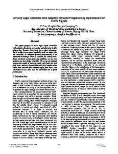
2 A QUARTER-CAR ACTIVE SUSPENSION SYSTEM MODEL 2.1 Modelling of the active suspension system A quarter-car active suspension system is introduced in this section. This system entails a suspension mechanism and a control unit as shown in Fig. 1 [1–16], in which the suspension mechanism is composed of a spring, a mass, a damper, and a hydraulic actuator. The basic assumptions are that the tyre always contacts the road surface and that the function of the tyre is approximately substituted by a spring and unsprung mass. The sprung mass of the vehicle body is considered as a rigid body [14]. From Fig. 1, the dynamic state variable equations of an active suspension system can be derived as m z¨ =−k (z −z )−b (z˙ −z˙ )+F s s s s u s s u m z¨ =k (z −z )+b (z˙ −z˙ )−k (z −z )−F u u s s u s s u u u r (1) JAUTO379 © IMechE 2007
Dynamic sliding-mode controller with fuzzy adaptive tuning
419
2.2 Modelling of the hydraulic actuator For a four-way valve–piston hydraulic system, the dynamic model of a hydraulic servo-actuator is complicated and exhibits non-linear behaviour. It is necessary to simplify the hydraulic servosystem model for the controller design. In this paper, the servovalve dynamics are assumed to be fast enough that they can be treated as constant for modelling the simplified hydraulic servosystem. The dynamics of the hydraulic actuator can be expressed as F˙ =−bF−aL2(z˙ −z˙ )+cLQ(F, u)u s u
(3)
where
C
F Q(F, u)=sgn P −sgn(u) s L
where z −z and z −z are the suspension stroke s u u r and tyre’s deflection respectively; z is the vertical r ground displacement caused by road unevenness; F is the active force provided by the hydraulic actuator. The active force F is provided by the hydraulic actuator, which is placed between the unsprung mass and the chassis. The state vector Z, the control ˜ , and the external disturbance vector input vector U W are defined as Z=[z , z˙ , z , z˙ ]T=[z , z , z , z ]T s s u u 1 2 3 4 ˜ =[F ]=[u˜], U W=[z ]=[w] r Then, the state space equation (2)
can be obtained, where 1 0 0 u t 0 N N k b N N − ks − bs s s N m m m m N s s s s N A= N 0 0 0 1 N N N N b k +k b N N ks s s u s − − v m m m m w u u u u 0 u t 0 N N 1 N N 0 N m N s N, D= 0 B= N N 0 N k N N u N− 1 N m v m w u u
CD
JAUTO379 © IMechE 2007
K
and u is the control input voltage of the servovalve. For a more detailed description of the hydraulic actuator dynamics, see references [16], [24], and [25].
Fig. 1 Active suspension system model
˜ +DW ˙ =AZ+BU Z
D SK
F P −sgn(u) s L
2.3 Road profile model In general, vibration and shock are the typical road disturbances during the process of vehicle roadrunning and handling. Vibrations can be specified as a consistent random process with a ground displacement power spectral density (PSD). Shocks are discrete events of short duration and high intensity, which are caused by a pronounced bump or pothole on a smooth road. Therefore, PSDs of a road profile [3] and a bump disturbance [22] are adopted in the quarter-car model as external road disturbances in this paper. PSD has been used by many researchers as the typical road disturbance input that can be expressed by
A B
g −c G (g)=G x x0 g 0
(4)
where the reference spatial frequency g can be 0 defined as g =0.1(1/m); c is a constant that is 0 described as an approximate value c#2. For the frequency f , the expression f =gv is used in this paper. Consequently, PSD ground displacement can be deduced from equation (4) as G gc vc−1 G ( f )= x0 0 x fc
(5)
where c=2 is introduced into equation (5) and the PSD ground velocity is given as G ( f )=(2p f )2G ( f )=4p2G g2 v x˙ x0 x0 0
(6)
Proc. IMechE Vol. 221 Part D: J. Automobile Engineering
420
Yun-Qing Zhang, Yong-Sheng Zhao, Jingzhou Yang, and Li-Ping Chen
Hence, the ground velocity is introduced into the road disturbance and viewed as a white-noise signal. More detailed descriptions of PSD have been provided by Chen et al. [3] and Hrovat [26].
the dynamic sliding-mode controller and to improve the robustness to parameter uncertainty and external disturbances, the fuzzy adaptive tuning approach is introduced into the proposed controller. 3.1 Inner-loop controller
3 CONTROLLER DESIGN FOR AN ACTIVE SUSPENSION SYSTEM To improve the active suspension system performance, a controller with two control loops is depicted in this section, as shown in Fig 2. The inner-loop controller produces the hydraulic actuator input voltage u, which makes the actuator force F track the desired force F . The hydraulic actuator nond linearities are treated by applying the feedback linearization technique which requires that both the force F and its rate F˙ of change as shown later in d d equations (7) and (8) respectively, are available. The outer-loop controller obtains the desired force F for d satisfying the active suspension performance requirement according to the external perturbation conditions. However, the rate F˙ of change in the control d force has to be computed, and hence the inner-loop controller is unstable when a discontinuous jump in F˙ occurs. This problem can be solved by introducing d a dynamic sliding-mode control method in the outer control loop. The rate F˙ of change in force can d be directly computed and exported to the inner control loop as an input command. Furthermore, the chattering phenomenon of the control force F can d also be alleviated by the dynamic sliding-mode controller. However, the robustness and stability of the proposed controller are key problems for the active suspension system, and the lifetime of the components and the maximization of passenger comfort must be considered as important evaluation indices. In order to alleviate the chattering phenomenon of
A feedback linearization control technique for the hydraulic actuator has been studied by D’Amato and Viassolo [16] and Lin and Kanellakopoulos [27], and the same method as the inner control loop of the proposed controller is adopted. Assuming the actuator force F does not exceed the maximum force value of the hydraulic actuator, which is slightly less F max than P L, the inner control loop can be described as s –h (7) u= cL √P −sgn(h–) sat (F )/L s Fmax where the saturation function sat (·) limits the F – is maximal force with saturation levelmaxF and h max defined by h– =aL2(z˙ −z˙ )+(b−l ) sat (F )+l (F +x) s u t Fmax t d +F˙ +x˙ d x˙ =−l x−k l [F−sat (F )] t c c Fmax
(8)
The parameters l , l , and k are positive constant c t c values. Substituting equation (7) into equation (3), the tracking error equation of the inner control loop can be obtained when |F|0, the inner-loop d t controller is an exponentially stable first-order linear time-invariant system. However, to obtain the
Fig. 2 Scheme of the active suspension controller Proc. IMechE Vol. 221 Part D: J. Automobile Engineering
JAUTO379 © IMechE 2007
Dynamic sliding-mode controller with fuzzy adaptive tuning
dynamics characteristic for tracking the error e, the parameters for the inner-loop controller are chosen as l =1300, l =2200, k =20 (10) t c c On the other hand, the second section of state x in equation (8) will be activated to restore F back to [−F , F ] when the actuator force exceeds the max max limited maximum value F . Then, the stability of max the feedback linearization (equation (7)) can be effectively held during the non-normal conditions.
421
where l is a positive value. Here, the control problem of the dynamic sliding mode is to find a control law ˙˜ so that the state Z remains on the dynamic sliding U surface s=0. Hence, a bounded stability dynamic system can be obtained, and a conventional sliding surface s=0 can also be met during the design of the controller. Then, the Lyapunov stability condition ˙ =sΩs˙