Hindawi Publishing Corporation International Journal of Distributed Sensor Networks Volume 2015, Article ID 870607, 10 pages http://dx.doi.org/10.1155/2015/870607
Research Article Dynamic Interference Control in OFDM-Based Cognitive Radio Network Using Genetic Algorithm Hamza Khan and Sang-Jo Yoo The School of Information and Communication Engineering, Inha University, Incheon 402-020, Republic of Korea Correspondence should be addressed to Sang-Jo Yoo;
[email protected] Received 3 June 2015; Revised 14 September 2015; Accepted 15 September 2015 Academic Editor: Lin Chen Copyright © 2015 H. Khan and S.-J. Yoo. This is an open access article distributed under the Creative Commons Attribution License, which permits unrestricted use, distribution, and reproduction in any medium, provided the original work is properly cited. In OFDM-based cognitive radio networks, minimizing the interference caused to the primary user (PU) by the substantial amount of out-of-band (OOB) emission is a great challenge. In this paper, we propose a dynamic interference control method using the additive signal side lobe reduction technique and genetic algorithm (GA) in CR-OFDM systems. Additive signal side lobe reduction technique is based on adding a complex array to modulated data symbols in the constellation plane for side lobe reduction in OFDM system. In the proposed method, GA generates optimum additive signal which can effectively reduce the OOB signal interference to the primary system. The GA also strives to keep the interference below a predefined tolerable limit and at the same time it maximizes secondary user’s transmission opportunity. The results show that the side lobes of the OFDM-based secondary user signal can be reduced by up to 38 dB and the PU interference tolerable limit can be satisfied at the cost of a minor addition in bit error rate (BER). The results further show that the proposed method delivers better performance as compared to non-GA additive signal method in terms of side lobe reduction as well as BER.
1. Introduction The inefficient usage of existing spectrum can be improved through opportunistic access to the licensed bands by secondary users (SUs) without interfering or keeping the interference under a tolerable level to the existing primary users (PUs). Cognitive radio (CR) technology enables the SUs to determine which portion of the spectrum is not used by the PUs [1]. The overall implementation of the cognitive radio network (CRN) consists of spectrum sensing, interference control, and dynamic spectrum access. Spectrum sensing and dynamic spectrum access techniques allow determining which portion of the spectrum is available, selecting the best available channel, coordinating access to this channel with other users, and vacating the channel when a licensed user is detected. The CR users also need to make sure that there is no harmful interference caused to the PUs with interference control [2, 3]. Orthogonal frequency-division multiplexing (OFDM) is considered an attractive candidate in CRNs because of having the quality of transmitting over the noncontiguous
frequency bands. OFDM is also a good option for realizing a transmission system which does not require a continuous transmission band. Therefore, it is suitable for spectrum sharing in CRNs [4]. However, a major trade-off of CROFDM signals is their large out-of-band (OOB) side lobe power. The leakage power can greatly interfere with the existing neighboring primary transmissions. It is important to minimize these side lobes to keep the interference under the tolerable level in order to allow spectrum sharing with primary system. Several techniques have already been proposed for OFDM side lobe suppression. In [4], subcarriers lying at the border of the OFDM spectrum are deactivated by inserting guard bands and windowing of the transmitted signal in frequency domain. However, inserting a guard band results in wastage of the available bandwidth, and windowing the OFDM transmitted signal results in prolonged symbol duration. In [5] and [6], techniques with cancellation carrier and weighting the subcarrier are proposed, respectively. Both of these techniques require complicated optimization, which makes them very hard to implement in real time. In
2
International Journal of Distributed Sensor Networks X1 = x1 + d1
Input bits
xn
Symbol mapper
Parallel to serial converter
n = 1, 2, . . . , N
.. .
xN
Side lobe suppression parameter adding
x1
.. .
N-point IFFT
XN = xN + dN d = (d1 , d2 , . . . , dN ) GA optimization of additive signal
Pth
P(f∗ )
Primary interference threshold level
X(1)
.. .
Add cyclic prefix and parallel to serial converter
D/A
fc
X(N)
f∗
Primary signal detector
Sensing
Secondary system power spectral density level estimation OFDM system blocks Additional CR blocks Interference reduction blocks
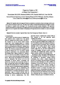
Figure 1: OFDM system combined with proposed dynamic interference control model including GA and CR blocks.
[7], multiple choice sequence (MCS) technique is used for reducing the side lobe power level. However, the throughput of the system is reduced due to the amount of transmission of side information other than data. In this paper, we propose a dynamic interference control technique for OFDM-based CR system. In additive signal method (ASM) [8], an additive complex signal sequence is added with the original transmit data sequence to be transmitted by the OFDM user. In the proposed technique, we used genetic algorithms (GA) to find an optimal additive sequence for major side lobe suppression. GA is a search technique used to find the best possible solution to optimization problems [9]. It is an evolutionary algorithm which utilizes evolutionary biological techniques like mutation, crossover, and survival of the fittest. The GA converges for an optimal additive sequence to be added with the symbols transmitted by the OFDM-based SU, with constraints like keeping the SU OOB transmission under PU tolerable limit and low BER. The main contributions of this paper are as follows: (i) We develop a dynamic interference control model using GA to efficiently reduce the interference at 𝑓∗ , in which 𝑓∗ is the closest boundary frequency of the primary system sensed to the secondary system. Our proposed scheme guarantees the reduction of SU interference at 𝑓∗ down to the acceptable interference threshold defined by PU. (ii) We propose a new fitness function of the GA to effectively manage the SU’s interference to the PUs within the defined interference safe region. Using the proposed fitness function, additive complex signal is fast converged to the optimum parameter set. (iii) With the precise side lobe reduction control, we can not only avoid any harmful interference to the
primary users but also reduce the possible BER loss due to the deviations in the constellation. The rest of this paper is organized as follows. In Section 2, the system model is introduced. In Section 3, the proposed scheme is explained. Simulation results are shown in Section 4. Finally, we conclude this paper in Section 5.
2. System Model We consider an OFDM-based CR system throughout this paper. In this section, first we describe the proposed dynamic interference control CR-OFDM model, followed by detailed explanation of the GA optimization model. 2.1. Interference Control OFDM-Based Cognitive Radio Model. OFDM has recently been considered as a preferred scheme to be applied in CR systems [2, 4]. In CR system, every CR node needs to sense the spectrum by using spectral analysis techniques. Fast Fourier transform (FFT) can be used for spectral analysis while at the same time acting as an OFDM demodulator. The shortcoming of OFDM is the large side lobes of the frequency response filters that characterize the channel associated with each subcarrier. The large side lobes result in significant interference to other SUs and PUs. To tackle this problem in CR, we design a dynamic interference control system for OFDM-based CR users. As shown in Figure 1, the side lobe suppression OFDM model proposed in [8] is further extended by using GA and applied to CRNs. An OFDM system with 𝑁 subcarriers is considered. The input bits are mapped to symbols by applying quadrature amplitude mapping (QAM) or phase shift keying (PSK), thus having 𝑁 complex-valued data symbols 𝑥 = (𝑥1 , 𝑥2 , . . . , 𝑥𝑁). These data symbols are serial to parallel converted and fed into a side lobe suppression unit. The suppression unit adds a
International Journal of Distributed Sensor Networks
3
Im
0 R xn dn
1
Normalized PSD
Xn = xn + dn
Re 1
−1
OOB recording
−20
−1
−40 −60 −80 −100 −120
Figure 2: Additive signal example in 4-QAM constellation.
OFDM signal
Minimum tolerable interference Primary appearance
−1.18 −1.15 −1
0 1 1.15 1.20 Normalized frequency (MHz)
1.25
1.50
Figure 3: OFDM-based CR coexisting with PU.
complex additive signal array 𝑑 = (𝑑1 , 𝑑2 , . . . , 𝑑𝑁) with the data symbols forming a modified complex array of symbols 𝑋 = (𝑋1 , 𝑋2 , . . . , 𝑋𝑁). The additive signal is determined by the proposed GA optimization algorithm that can reduce the interference under the PU’s tolerable interference threshold. The threshold is automatically computed using primary signal bandwidth and allowed interference level. Figure 2 shows the addition of additive signal 𝑑 with the data symbols 𝑥, in which 𝑑𝑛 is chosen appropriately within a limited circle of radius |𝑅| for BER control. The resultant data symbols can be written as 𝑋𝑛 = 𝑥𝑛 + 𝑑𝑛 .
(1)
Finally, the resulting data symbols are modulated onto the subcarriers using inverse fast Fourier transform (IFFT). Then, a guard interval in the form of cyclic prefix is added. To avoid causing harmful interference to the PU frequency band that is in operation, spectrum sensing is needed for the CRs [10, 11]. If primary signal structure is known, the usual way to detect a primary signal is coherent detection [12]. Current alternative techniques for primary detection are energy detection and feature detection. In practice, a combination of different techniques may be needed in order to handle a variety of situations. As shown in Figure 1, the primary signal detector performs spectrum sensing. In case of detection of PU, the primary interference threshold 𝑃th and secondary system OOB power 𝑃(𝑓∗ ) at frequency point 𝑓∗ are input to the GA block. In the proposed method, the interference is evaluated at the frequency point 𝑓∗ outside the main transmission frequency of CR-OFDM according to the sensing result of the primary signal detector. 𝑓∗ is the closest boundary frequency of the primary system sensed to the secondary system. Figure 3 shows a scenario of CROFDM coexisting with a licensed PU. Even though the CROFDM operating band is quite different from that of primary system, the side lobes from OFDM-based CR are far above the primary user’s acceptable interference threshold. Such a case could be extremely harmful in terms of primary interference and will be addressed in this paper. To bring the interference to the primary system below acceptable levels, further side lobe reduction is required. The
GA is used to derive the optimum additive signal 𝑑∗ , which guarantees that the maximum interference to primary system is always lower than the predefined threshold. It should also be noted that generally lower side lobes are achieved by either reducing secondary transmission power or sacrificing BER. In this paper, using GA, we can maximize the secondary transmission opportunity and minimize the BER increase by maintaining the interference level 𝑓∗ under the threshold but very close to the threshold value dynamically. The GA keeps considering 𝑃(𝑓∗ ) and 𝑃th and generates the optimum set of 𝑑 iteratively. Afterwards, the values are added with the data symbols as given in (1). The detailed GA optimization [13, 14] algorithm is explained in the proceeding section. In addition to the conventional OFDM technology, the proposed GA optimization method can be applied to other evolutional versions of multicarrier systems such as filter bank multicarrier (FBMC) and generalized frequency division multiplexing (GFDM) systems [15, 16]. FBMC systems are based on the orthogonal lapped transform [17] and filter bank theory [18]. GFDM systems add flexibility of choosing a suitable pulse, such as a rooted raised cosine (RRC) or raised cosine (RC). This pulse shaping technique brings about the advantage of out-of-band radiation. Like FBMC and GFDM, all the evolutional versions of OFDM involve mapping of bits into symbols to be transmitted. Therefore, similar to the OFDM system model, the information bits are first mapped to symbols 𝑋 drawn from the complex QAM constellation which allows us to apply the proposed model effectively for the FBMC and GFDM systems by adding the additive vector 𝑑 optimized by GA to the symbol vector 𝑋. Figure 4 shows the system of FMBC, in which the proposed optimization mechanism is cooperated. 2.2. The Genetic Algorithm (GA) Model. GA is a type of feature selection algorithm based on the idea of natural selection and natural genetics [9]. This search is performed based on an objective function, also called a fitness function. The GA tries to generate results such that the fitness function reaches a minimum or maximum value and finds the solutions of
4
International Journal of Distributed Sensor Networks Xn = xn + dn
Bits
Constellation mapping
Real (Xn )
xne
Cosine filter bank
Sn
Optimum dn vector
xnS
Sine Imag (Xn )
filter bank
N/2 delay
Genetic algorithm PU’s interference threshold level
PU signal detector
Sensing
SU signal level estimation
FBMC blocks Proposed interference reduction blocks
Figure 4: Block diagram of an implementation of the FBMC transmitter with proposed interference reduction scheme.
variables for the best-possible result. Individuals or current approximations are encoded as strings (chromosomes), composed over some numbers referred to as genes, so that the genotypes (chromosome values) are uniquely mapped onto the real decision variables (phenotypic) domain. The representation used in this paper is binary numbers {0, 1}. A problem with 𝑁 variables (in our case the additive signal vector) may be mapped onto the chromosome with selected number of bits. The number of bits is reflecting the range of the decision variables (range of |𝑅|). Binary values in chromosome do not give any information related to the problem by themselves unless a meaning is applied to the representation. Having decoded the chromosome into the decision variable domain, it is possible to assess the performance or fitness of individual members of the population. However, the search process will operate on the encoding of the decision variables rather than the decision variables themselves. The initial random population is subject to treat with crossover and mutation after being evaluated with the proposed fitness function. The evaluation of the population and the improvement of additive signal are continued until the stopping criteria are reached. The chromosome representation in our evaluation is [𝑑1 , 𝑑2 , . . . , 𝑑𝑁]; therefore the population consists of the following 𝑀 individuals: 𝑑11 [𝑑 [ 21 [ [ . [ . [ .
𝑑12 ⋅ ⋅ ⋅ 𝑑1𝑁 𝑑22 .. .
Individual 1 ] ⋅ ⋅ ⋅ 𝑑2𝑁 ] Individual 2 ] .. ] .. ] d . ] .
(2)
[𝑑𝑀1 𝑑𝑀2 ⋅ ⋅ ⋅ 𝑑𝑀𝑁] Individual 𝑀, where 𝑑𝑀𝑁 represents a complex variable for the 𝑁th additive signal of the 𝑀th individual.
3. The Proposed GA-Based Interference Control Scheme In the proposed scheme, the side lobe suppression of OFDMbased CR is achieved by adding the frequency domain value 𝑥𝑛 with an additive value 𝑑𝑛 . This addition is done in such a way that the resulting power spectral density (PSD) in PU region, that is, primary operating frequency, is less than the predetermined threshold 𝑃th . Now the optimization problem becomes as follows: 𝑁 1 FFT 𝑃 (𝑓) = ∑ √𝑝𝑛 (𝑥𝑛 + 𝑑𝑛 ) 𝑁FFT 𝑛=1 (3) 2 (1+𝛼)𝑡𝑢 ⋅∫ 𝑔 (𝑡) 𝑒−𝑖2𝜋(𝑓−𝑓𝑛 )𝑡 𝑑𝑡 , −(1+𝛼)𝑡𝑢 where 𝑃(𝑓) is interference at frequency 𝑓 and 𝑑𝑛 is the additive signal on subcarrier 𝑛. 𝑁FFT (𝑁) is the number of FFT points, 𝑇𝑢 is the useful signal duration, 𝑔(𝑡) is the window function, and 𝛼 is the roll-off factor of the window, while 𝑓𝑛 , 𝑝𝑛 , and 𝑥𝑛 are the respective frequency, allocated power, and symbol from QAM mapping on the subcarrier 𝑛, respectively. Equation (3) shows that, by setting the parameters such as allocated power (𝑝𝑛 ), symbol amplitude (𝑆𝑛 = 𝑥𝑛 + 𝑑𝑛 ), and window (𝑔(𝑡)), we can suppress the side lobes power at PU frequency which is denoted as 𝑃(𝑓). In this paper, to achieve the optimal interference control, we have decided to alter the symbol amplitude by making use of [𝑑1 , 𝑑2 , . . . , 𝑑𝑁]. In order to avoid the BER loss, the range of 𝑑𝑛 is kept limited to a circle with radius |𝑅| [8]. In this paper, we also propose a fitness function for the optimization of 𝑑 = [𝑑1 , 𝑑2 , . . . , 𝑑𝑁]. The algorithm strives to reduce the OOB interference at a single frequency point 𝑓∗ outside the transmission bandwidth of the CR-OFDM.
International Journal of Distributed Sensor Networks
5 In general, the larger range diversity of 𝑑 = [𝑑1 , 𝑑2 , . . . 𝑑𝑁] results in more side lobe reduction, that is, smaller 𝑃(𝑓∗ ). However, it also results in larger bit error rate because the derived symbol set [𝑥1 + 𝑑1 , 𝑥2 + 𝑑2 , . . . , 𝑥𝑁 + 𝑑𝑁] becomes weaker to noise and fading effect. Therefore, we derive an optimum 𝑑∗ that keeps 𝑃(𝑓∗ ) close to the threshold 𝑃th . Now our optimization problem can be reduced to
Primary CR-OFDM
𝑑∗ = arg min 𝑃 (𝑓∗ ) − 𝑃th .
f∗
𝑑
The entire procedure of the proposed GA-based interference control scheme is shown in Algorithm 1. At first, chromosomes are randomly initialized. The resultant chromosomes then transform to phenotypes (complex variables). The additive vectors are analyzed in OFDM system iteratively as illustrated in Figure 1. The GA converges to the optimum 𝑑∗ according to the following minimizing fitness function:
Primary band (a)
Primary A
(6)
(i) if 𝑃(𝑓∗ ) > 𝑃th
Primary B
𝑃 (𝑓∗ ) − 𝑃 th × 𝛼1 𝐹 = ∗ 𝑃 (𝑓 ) + 𝑃th
f∗
(7a)
(ii) if 𝑃th − Δ ≤ 𝑃(𝑓∗ ) ≤ 𝑃th 𝑃 (𝑓∗ ) − 𝑃 th × 𝛼2 𝐹 = − 𝑃 (𝑓∗ ) + 𝑃th
(7b)
(b)
(iii) if 𝑃(𝑓∗ ) < 𝑃th − Δ
Figure 5: Target frequency on primary band.
The frequency 𝑓∗ is the target point to control CR-OFDM system side lobes, in which 𝑓∗ is the closest frequency of the detected primary system to the CR-OFDM system as shown in Figure 5. In this paper, we only consider frequency bins for the integer multiple harmonics of CR-OFDM subcarrier. It is obvious that if we maintain the side lobe at 𝑓∗ under the threshold, then for all primary user’s operating band, the interference is always lower than the threshold because SU’s side lobe function 𝑃(𝑓) is a monotonically decreasing function. To guarantee that secondary transmission added to the existing interference must not exceed the allowed limit at the licensed receiver, the following conditions should be satisfied: 𝑃𝐼𝑇 (𝑓∗ ) = 𝛿𝑃 (𝑓∗ ) + 𝑃𝐼 (𝑓∗ ) ≤ 𝜅𝑇𝐿 (𝑓∗ ) ,
(4)
where 𝑃𝐼𝑇 (𝑓∗ ) is the total interference power to the primary receiver, 𝑃(𝑓∗ ) is the unlicensed user transmit power, 𝑇𝐿 (𝑓∗ ) is the interference temperature limit, 𝜅 is the Boltzmann constant equal to 1.3806503 × 10⁻²³ , and 𝛿 is the propagation loss factor. Therefore, the threshold 𝑃th can be determined as 𝑃th =
[𝜅𝑇𝐿 (𝑓∗ ) − 𝑃𝐼 (𝑓∗ )] . 𝛿
(5)
𝑃 (𝑓∗ ) − 𝑃 th × 𝛼2 , 𝐹 = 𝑃 (𝑓∗ ) + 𝑃th
(7c)
where Δ is the marginal range specified for GA to converse to the threshold and 𝛼1 and 𝛼2 are the weighting constants to keep the fitness value in interference safe region. The proposed fitness function is a decreasing function. Figure 6 shows the behavior of the proposed fitness function. According to the proposed fitness function, the GA tends to minimize the objective value 𝐹 in an iterative manner by making generational improvements in chromosome. GA reaches the threshold using (7a). After that, the GA further converges down Δ = 5 dB below the threshold using fitness function (7b) to be on the safe side. The fitness function (7c) restricts 𝑃(𝑓∗ ) in interference safe region and does not go below 𝑃th −Δ for BER control. It should be noted that 𝑝(𝑓∗ ) < 𝑃th −Δ results in smaller SU’s OFDM system main lobe power, even though it satisfies the interference constraint. Therefore, the SNR is decreasing and the BER loss is also increasing. This behaviour is not desirable, and that is why fitness function 𝐹 is designed to increase at the region of 𝑃(𝑓∗ ) < 𝑃th − Δ with 𝛼2 parameter. In recent 5G OFDM-based LTE (Long Term Evolution) and WiMAX (Worldwide Interoperability for Microwave Access) systems, one of the key components is the RF
6
International Journal of Distributed Sensor Networks
Initialize GA parameters; (2) Initialize chromosomes; // create genotypes Convert chromosomes to phenotypes; (4) Initialize OFDM parameters while maximum number of generations is not reached do (6) Generate bit stream; Modulate using 4-QAM; // 𝑥𝑛 generated (8) for 𝑖 = 1, 𝑖 < size(Phenotypes), 𝑖 + + do 𝑋𝑛 = 𝑥𝑛 + phenotype(𝑖, :); // add the rows (individuals) of chromosome iteration wise with 4-QAM modulated symbols. (10) for 𝑗 = 1, 𝑗 < frequency, 𝑗 + + do Perform inverse fast fourier transform using newly created symbols; (12) Add cyclic prefix; end for (14) Compute 𝑃(𝑓∗ ) of current individual if 𝑃(𝑓∗ )[𝑖] > 𝑃th then 𝑃 (𝑓∗ ) − 𝑃 th × 𝛼1 ; (16) 𝐹 = ∗ 𝑃 (𝑓 ) + 𝑃th else (18) if 𝑃th − Δ ≤ 𝑃(𝑓∗ )[𝑖] ≤ 𝑃th then 𝑃 (𝑓∗ ) − 𝑃 th × 𝛼2 ; 𝐹 = − 𝑃 (𝑓∗ ) + 𝑃th (20) else if 𝑃(𝑓∗ )[𝑖] < 𝑃th − Δ then (22) 𝐹 = |(𝑃(𝑓∗ ) − 𝑃th )/(𝑃(𝑓∗ ) + 𝑃th )| × 𝛼2 ; // Evaluate and save fitness values of all individuals and return the array. end if (24) end if end if (26) Calculate the lowest 𝑃(𝑓∗ ) and fitness value of current generation; end for; // performance check of current population. (28) Calculate the best fitness value in current generation; Assign rank to individuals; (30) Select individuals on the basis of fitness; // Best individuals which flows throughout. Perform crossover; (32) Perform mutation; Reinsert the best individuals in current population; (34) Evaluate the chromosome in problem domain; // Repeat from line 8 to 27 Calculate the best fitness value in current generation; (36) end while; Algorithm 1: GA-based interference control.
power amplifier. Mostly the RF amplifiers used commercially are not linear. There are several researches on the effect of nonlinear power amplifier on the spectral regrowth in wireless communication systems [19]. In general, for a closedform expression for the autocovariance function of the PA output, its Fourier transform yields the output power spectral density function. Usual nonlinear effects on the transmitted OFDM signal are spectral spreading of the OFDM signal and warping of the signal constellation in each signal [20, 21]. We believe that our proposed scheme is generalized enough to incorporate with the nonlinear PA spectral models. The effect of nonlinear power amplifier only requires the change of the power spectral density function of (3). The implementation and analysis that consider the nonlinear power amplifier are left as a further study.
4. Simulation Results A simple OFDM system scenario is considered. We used QAM modulation scheme applied on 128 subcarriers, whereas rectangular windowing is used. The simulation parameters are shown in Table 1. There are 128 parameters [𝑑1 , 𝑑2 , . . . , 𝑑128 ] in GA, which are actually the additive signals and also equal to the modulated symbols. One complex parameter variable is expressed by 8 bits in chromosome. Minimizing fitness functions defined in (7a), (7b), and (7c) are used and the primary interference threshold 𝑃th is kept either at −30 dB or at −60 dB. The normalized frequency of the secondary OFDM system is −0.34 to +0.34 as shown in Figure 7. Throughout the simulation we consider different 𝑓∗ from 0.4 to 1.0 (in terms of normalized
International Journal of Distributed Sensor Networks
7 10 0
F
Interference safe region
0
Pth = −60 dB 𝛼1 = 2, 𝛼2 = 1 Δ = 5 dB
𝛼2 𝛼2 Δ
−20
PU main band
SU main band
−30 −40 −50 −60 −70
−15 −20 −25 −30 −35 −40 −45 −50 −55 −60 −65 −70 −75 −80
Pth
Side lobes interfering
−10
Power spectral density (dB)
𝛼1
PU’s allowable interference threshold
−80
∗
P(f ) (dB)
−90 −1 −0.8 −0.6 −0.4 0 0.4 0.6 0.8 Normalized frequency (MHz)
Figure 6: Minimizing fitness function versus 𝑃(𝑓∗ ).
1
1.2 1.3
(a) PSD of the original secondary OFDM signal and primary signal
Table 1: Simulation parameters.
10
frequency) on the right side of the OFDM signal. Figure 7 further shows the effect of the interference control of the proposed mechanism. As shown in Figure 7(a), original OFDM system side lobes give harmful interference to the primary users because at the primary band the interference level from the secondary OFDM system exceeds the primary user’s allowable interference threshold. When the proposed GA-based side lobe reduction mechanism is applied, as shown in Figure 7(b), the interference to the primary users is tightly controlled within the interference safe region. Figure 8 shows the change of fitness value as GA generations are moving on. The decreasing objective value shows the decrease of side lobe power at 𝑓∗ = 1. For Figure 8, additive complex variable range |𝑅| for boundary 𝑑 vector is set to the radius of 0.5 and 0.3. In both cases, GA achieves fast convergence to the optimum value in just 15 generations. In case of |𝑅| = 0.3, GA converges slightly slower because of the limited search space. This shows that as we increase |𝑅| we can get better reduction in the side lobes. Figure 9 shows the obtained fitness value when we vary 𝑓∗ from 0.4 to 1.0. Different 𝑓∗ indicates different primary appearing frequency band. In both variable search radiuses, the GA reaches the optimal value from 0.6 and onwards. We observe that the fitness performance of |𝑅| = 0.5 is slightly better than that of |𝑅| = 0.3. As we can see in Figure 9, at 𝑓∗ = 0.4, the achieved fitness value is little higher than
0 Power spectral density (dB)
Value 40 0.7 0.001 to 0.01 20 128 −60 dB 5 dB 2 1 0.4 to 1.0
−10 −20
PU main band
−30 Interference safe region
−40 −50 −60 −70 −80
−90 −1 −0.8 −0.6 −0.4 0 0.4 0.6 0.8 Normalized frequency (MHz)
1
1.2 1.3
(b) PSD of the proposed interference controlled secondary OFDM signal and primary signal
Figure 7: Power spectral density of primary and secondary signals.
0.3 0.25 0.2 Fitness (F)
Parameters Population size Crossover rate Mutation rate Iterations 𝑁FFT (= 𝑁) 𝑃th Δ 𝛼1 𝛼2 𝑓∗
0.15 0.1 0.05 0 −0.05
0
2
4
6
8 10 Generations
12
14
16
|R| = 0.5 |R| = 0.3
Figure 8: GA fitness convergence versus the number of iterations at 𝑓∗ = 1.
8
International Journal of Distributed Sensor Networks 0.04
0.1
0.03 BER
Fitness (F)
0.02 0.01 0
0.095 0.09 0.085 0.4
−0.01
0.5
−0.02 −0.03 −0.04 0.4
0.5
0.6 0.7 0.8 Frequency point f∗
0.9
1
Figure 9: Acquired GA fitness (𝐹) at last iteration on the respective target frequency 𝑓∗ .
BER
100
10−1
0
2
4
6
8
10
12
14
Eb/No |R| = 0.5, f∗ = 1 |R| = 0.5, f∗ = 0.4 |R| = 0.3, f∗ = 0.4
0.9
1
|R| = 0.5 |R| = 0.3
Figure 11: BER versus 𝑓∗ comparison of OFDM signal in Rayleigh fading with Eb/No fixed at 8 dB and with the effect of optimum 𝑑∗ acquired by GA.
|R| = 0.5 |R| = 0.3
10−2
0.6 0.7 0.8 Frequency point f∗
|R| = 0.3, f∗ = 1 OFDM reference
Figure 10: BER versus Eb/No comparison of OFDM signal in Rayleigh fading with the effect of optimum 𝑑∗ acquired by GA at different cases.
the optimal point. It indicates that the controlled interference level is slightly higher than the tolerable threshold. Because the primary operating frequency band is too close to the secondary system, it is very hard to exactly control the interference always below the threshold. In this case, we may set 𝑃th little higher than the required tolerable level. Figure 10 illustrates BER versus Eb/No curves of OFDM system with the effect of 𝑑∗ derived from different cases. A 4tap frequency selective Rayleigh fading channel is considered and 256 random bits are transmitted by the transmitter. The figure shows that as we increase |𝑅| the effect of acquired 𝑑∗ on BER performance also increases. However, the BER loss of the proposed method is not significant because of limiting |𝑅| under 0.5. Figure 11 shows the BER values of OFDM system with the effect of acquired 𝑑∗ sets by setting different target frequency 𝑓∗ . We observed that, in case of 𝑓∗ being closest to the OFDM
main band, we got a higher BER. Additionally, in case of variable radius 0.5, we got a higher BER as compared to |𝑅| = 0.3, because the larger variable radius causes more distortion in the constellation and consequently causes the higher BER. Figure 12 shows the comparison of the proposed scheme with ASM in power spectral density for the OFDM signal. The shortest primary appearance frequency point 𝑓∗ is 1.0. |𝑅| = 0.5 is used for both the proposed method and ASM. For the proposed method, the population size is 40 and the number of iterations is 16. For ASM, from the randomly generated one thousand sets of additive signals (𝑑𝑛 ), an optimum set is selected which generates the minimum interference at 𝑓∗ . As shown in Figure 12(a), in which the allowable threshold level of the primary system is −60 dB, the PSD of the proposed scheme successfully reduces the interference at 𝑓∗ within the interference safe region. However, ASM fails to control the side lobe interference under the required interference threshold. The PSD of ASM at 𝑓∗ (=1.0) is about 15 dB higher than the threshold. Meanwhile, in the proposed scheme, the side lobe suppression is acquired by the precise optimization of GA. Figure 12(b) shows the results when the allowable threshold level of the primary system is −30 dB. As we can see, the PSD acquired from the proposed scheme stays in the interference safe region. Meanwhile, the PSD from ASM shows too much reduction of side lobes. At 𝑓∗ , ASM reduces 15 dB more below the threshold. In general, more reduction in side lobes will cause more distortion in the constellation. In ASM, the side lobe reduction of OFDM signal is done without consideration of any constraints such as BER or interference threshold. This may cause too much reduction in the side lobes as in Figure 12(b), so it consequently can increase the BER. Figure 13 shows the BER comparison of the proposed scheme and ASM when the interference threshold is −30 dB. We can see that ASM scheme generates higher BER than that of the proposed scheme.
5. Conclusion In this paper, a technique that can dynamically control interference to PUs caused by OFDM-based SUs is proposed. The method is based on a small shift of the symbol in the symbol constellation plane by the addition of an additive signal. This
International Journal of Distributed Sensor Networks
9 10
10
Power spectral density (dB)
Power spectral density (dB)
0 −10 −20 −30 −40 −50 −60 −70 −1
0 −10 −20 −30
Interference safe region
−40 Interference safe region −0.8 −0.6 −0.4 −0.2 0 0.2 0.4 0.6 Normalized frequency (MHz)
0.8
1
OFDM reference Proposed scheme ASM
−50 −1
−0.8 −0.6 −0.4 −0.2 0 0.2 0.4 0.6 Normalized frequency (MHz)
0.8
1
OFDM reference Proposed scheme ASM
(a) The interference threshold = −60 dB
(b) The interference threshold = −30 dB
Figure 12: Comparison of the proposed method with ASM in power spectral density for the OFDM signal.
BER
100
and control the interference to the primary system under the allowable level with small loss in BER performance. The results further show that the performance of the proposed scheme is controlled as compared to non-GA ASM-based side lobe reduction scheme in terms of BER and also provides better side lobe reduction.
10−1
Conflict of Interests The authors declare that there is no conflict of interests regarding the publication of this paper. 10−2
0
2
4
6
8
10
12
14
Eb/No OFDM reference Proposed scheme ASM
Figure 13: BER comparison of proposed scheme and ASM (the allowable interference threshold = −30 dB).
Acknowledgment This research was supported by the MSIP (Ministry of Science, ICT and Future Planning), Korea, under the ITRC (Information Technology Research Center) support program (IITP-2015-H8501-15-1019) supervised by the IITP (Institute for Information & communications Technology Promotion).
References addition can lead to significant interference suppression of the OFDM-based SU to PUs. The interference to the primary user is avoided by the precise optimization of additive signal using GA, which helps satisfy the interference threshold defined by any licensed system. Simulation results show that our proposed scheme is effective in minimizing interference in OFDM-based CR systems. The overall achievable side lobe suppression is 38 dB. Additionally, the results show that increasing the radius of additive signal causes small loss in SNR performance but achieves better side lobe suppression. We observed that the dynamic additive signal optimization can successfully suppress the secondary system’s side lobes
[1] N. Hao and S.-J. Yoo, “Interference avoidance throughput optimization in cognitive radio ad hoc networks,” EURASIP Journal on Wireless Communications and Networking, vol. 2012, article 295, 2012. [2] T. A. Weiss and F. K. Jondral, “Spectrum pooling: an innovative strategy for the enhancement of spectrum efficiency,” IEEE Communications Magazine, vol. 42, no. 3, pp. S8–S14, 2004. [3] Federal Communications Commission, “Spectrum policy task force report,” ET Docket 02-135, Federal Communications Commission, 2002. [4] T. Weiss, J. Hillenbrand, A. Krohn, and F. K. Jondral, “Mutual interference in OFDM-based spectrum pooling systems,” in
10
International Journal of Distributed Sensor Networks Proceedings of the IEEE 59th Semiannual Vehicular Technology Conference, pp. 1873–1877, May 2004.
[5] S. Brandes, I. Cosovic, and M. Schnell, “Sidelobe suppression in OFDM systems by insertion of cancellation carriers,” in Proceedings of the IEEE 62nd Vehicular Technology Conference (VTC ’05), pp. 152–156, Dallas, Tex, USA, September 2005. [6] I. Cosovic, S. Brandes, and M. Schnell, “Subcarrier weighting: a method for sidelobe suppression in OFDM systems,” IEEE Communications Letters, vol. 10, no. 6, pp. 444–446, 2006. [7] I. Cosovic and T. Mazzoni, “Suppression of sidelobes in OFDM systems by multiple-choice sequences,” European Transactions on Telecommunications, vol. 17, no. 6, pp. 623–630, 2006. [8] I. Cosovic and T. Mazzoni, “Sidelobe suppression in OFDM spectrum sharing systems via additive signal method,” in Proceedings of the 65th IEEE Vehicular Technology Conference (VTC ’07), pp. 2692–2696, IEEE, Dublin, Ireland, April 2007. [9] J. D. E. Goldberg, Genetic Algorithms in Search, Optimization and Machine Learning, Addison-Wesley Longman Publishing, Boston, Mass, USA, 1989. [10] A. Ghasemi and E. S. Sousa, “Spectrum sensing in cognitive radio networks: requirements, challenges and design tradeoffs,” IEEE Communications Magazine, vol. 46, no. 4, pp. 32–39, 2008. [11] T. Y¨ucek and H. Arslan, “A survey of spectrum sensing algorithms for cognitive radio applications,” IEEE Communications Surveys and Tutorials, vol. 11, no. 1, pp. 116–130, 2009. [12] D. Cabric, S. M. Mishra, and R. W. Brodersen, “Implementation issues in spectrum sensing for cognitive radios,” in Proceedings of the Conference Record of the 38th Asilomar Conference on Signals, Systems and Computers, vol. 1, pp. 772–776, IEEE, Pacific Grove, Calif, USA, November 2004. [13] Y. Zhou, S. Pagadarai, and A. M. Wyglinski, “Cancellation carrier technique using genetic algorithm for OFDM sidelobe suppression,” in Proceedings of the IEEE Military Communications Conference (MILCOM ’08), pp. 1–5, San Diego, Calif, USA, November 2008. [14] E. Zitzler and L. Thiele, “Multiobjective evolutionary algorithms: a comparative case study and the strength pareto approach,” IEEE Transactions on Evolutionary Computation, vol. 3, no. 4, pp. 257–271, 1999. [15] S. Dikmese, S. Srinivasan, M. Shaat, F. Bader, and M. Renfors, “Spectrum sensing and resource allocation for multicarrier cognitive radio systems under interference and power constraints,” EURASIP Journal on Advances in Signal Processing, vol. 2014, article 68, 2014. [16] B. Farhang-Boroujeny and R. Kempter, “Multicarrier communication techniques for spectrum sensing and communication in cognitive radios,” IEEE Communications Magazine, vol. 46, no. 4, pp. 80–85, 2008. [17] H. S. Malvar, “Extended lapped transforms: properties, applications, and fast algorithms,” IEEE Transactions on Signal Processing, vol. 40, no. 11, pp. 2703–2714, 1992. [18] P. P. Vaidyanathan, Multirate Systems and Filter Banks, Prentice Hall, 1993. [19] G. T. Zhou and J. S. Kenney, “Predicting spectral regrowth of nonlinear power amplifiers,” IEEE Transactions on Communications, vol. 50, no. 5, pp. 718–722, 2002. [20] M. Majidi, A. Mohammadi, and A. Abdipour, “Accurate analysis of spectral regrowth of nonlinear power amplifier driven by
cyclostationary modulated signals,” Analog Integrated Circuits and Signal Processing, vol. 74, no. 2, pp. 425–437, 2013. [21] I. Ahmad, A. I. Sulyman, A. Alsanie, A. K. Alasmari, and S. A. Alshebeili, “Spectral broadening effects of high-power amplifiers in MIMO–OFDM relaying channels,” EURASIP Journal on Wireless Communications and Networking, vol. 2013, article 32, 2013.
International Journal of
Rotating Machinery
Engineering Journal of
Hindawi Publishing Corporation http://www.hindawi.com
Volume 2014
The Scientific World Journal Hindawi Publishing Corporation http://www.hindawi.com
Volume 2014
International Journal of
Distributed Sensor Networks
Journal of
Sensors Hindawi Publishing Corporation http://www.hindawi.com
Volume 2014
Hindawi Publishing Corporation http://www.hindawi.com
Volume 2014
Hindawi Publishing Corporation http://www.hindawi.com
Volume 2014
Journal of
Control Science and Engineering
Advances in
Civil Engineering Hindawi Publishing Corporation http://www.hindawi.com
Hindawi Publishing Corporation http://www.hindawi.com
Volume 2014
Volume 2014
Submit your manuscripts at http://www.hindawi.com Journal of
Journal of
Electrical and Computer Engineering
Robotics Hindawi Publishing Corporation http://www.hindawi.com
Hindawi Publishing Corporation http://www.hindawi.com
Volume 2014
Volume 2014
VLSI Design Advances in OptoElectronics
International Journal of
Navigation and Observation Hindawi Publishing Corporation http://www.hindawi.com
Volume 2014
Hindawi Publishing Corporation http://www.hindawi.com
Hindawi Publishing Corporation http://www.hindawi.com
Chemical Engineering Hindawi Publishing Corporation http://www.hindawi.com
Volume 2014
Volume 2014
Active and Passive Electronic Components
Antennas and Propagation Hindawi Publishing Corporation http://www.hindawi.com
Aerospace Engineering
Hindawi Publishing Corporation http://www.hindawi.com
Volume 2014
Hindawi Publishing Corporation http://www.hindawi.com
Volume 2014
Volume 2014
International Journal of
International Journal of
International Journal of
Modelling & Simulation in Engineering
Volume 2014
Hindawi Publishing Corporation http://www.hindawi.com
Volume 2014
Shock and Vibration Hindawi Publishing Corporation http://www.hindawi.com
Volume 2014
Advances in
Acoustics and Vibration Hindawi Publishing Corporation http://www.hindawi.com
Volume 2014