CMOS Logic Circuit Design by John P. Uyemura, 2002. Dynamic CMOS. In static
circuits at every point in time (except when switching) the output is connected to.
Very simple sequential memory circuits; amenable to synchronous logic. – High
density ... The basic dynamic logic gate concept is shown at left (top). – the pass ...
dynamic term-modal logic all logical operators except negation, conjunction ... world w â W and â just as in first-order logic â a variable assignment1 g that.
From deferential acceptance to âexposureâ of pseudo-scientific âlessonsâ that some .... the standard style used
â Rijksuniversiteit Groningen and IEG, Oxford University. ...... map, that maps every formula Ï of QL into a formula Ï
Univ. Nova de Lisboa. 2825 Monte da Caparica. Portugal. H. Przymusinska. Dept. Computer Science. California State. Polytechnic Univ. Pomona, CA 91768.
Dynamic circuits have a variety of properties for example for the n-network: •
Dynamic logic has higher speed than equivalent static family. • It occupies less
area.
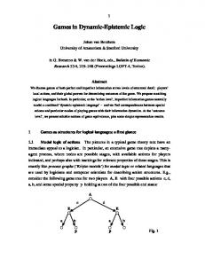
Games as structures for logical languages: a first glance. 1.1. Modal logic of
actions The pictures in a typical game theory text have an immediate appeal to a
...
If the average passenger weight is considered to be 75Kg, the number of .... fuzzy logic elevator group controllers have been proposed [14] in the past years, but ...
Some pioneer work along this direction has been done in the literature. .... calculus [REI 91]) rather than an ordinary set of formulas in reasoning about the do-.
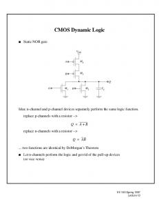
EE 105 Spring 1997. Lecture 13. CMOS Dynamic Logic s Static NOR gate. Idea:
n-channel and p-channel devices separately perform the same logic function.
Nov 3, 2005 - language, where a mechanism of information update lives together with one of ...... We will take small Greek letters to denote the utility values.
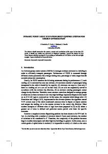
DYNAMIC FUZZY LOGIC FUNCTOR - CiteSeerX › publication › fulltext › Dynamic-... › publication › fulltext › Dynamic-...by JL Pérez-Silva · Cited by 3 · Related [email protected]. ABSTRACT. This is a fuzzy logical element from which
Hilbert-style proof calculus for dHL, prove it sound, and compare the expressive power ...... into automatic vs. interactive (or manual) approaches. Automation .... In International Workshop on Hybrid Logic, Patrick Blackburn, Thomas Bolander,.
Jun 1, 2003 - Department of Computer Science, University of Manchester, United ... puter science, ranging from program verification to such areas as ...
means: if the agent were to revise his beliefs with α, he would believe β. ..... believing that we do not believe α), then ¬Bα should still be true in the contracted ...
programs are capable of searching the web for the cheapest books, advising users ... ing approach to build such complex agents introduces methods and .... agent is more committed to choose α than to choose β if and only if the best possible.
I certify that I have read Reliability Analysis of Dynamic Logic Circuits under
Transistor. Aging Effects in Nanotechnology by Milana Ram, and that in my
opinion ...
Jun 28, 2017 - co-expression and clustering algorithms (Faith et al., 2007;. Margolin et al. .... As in the temporal transcriptional switch model of Jenkins et al.
he Arithmetic Logic Unit (ALU) is the basic building block of any processor for performing the arithmetic and logical operations. he data to be operated on ...
logic, notably Harel, Kozen and Parikh [4], Nishimura [6], Pratt [9], etc. .... h by is(/7) and fs(/i) respectively. A path ... (5) 7r([a]^4, MO = 1 iff for any /? e pr(a), is (/?) ...
Jun 1, 2003 - influence of the substitution rule on the properties of these logics and ...... to (¬q â Dq) â Dq. The following equivalences complete the proof.
Circuits. Lecture 19. Dynamic Logic. EE141. 2. EECS141. 2. Lecture #19.
Administrative Stuff. ❑ Project phase 1 due on Thursday. ▫ Report template
posted on ...
EE141-Fall 2007 Digital Integrated Circuits
Dynamic Logic Lecture 19 Dynamic Logic
EE141 EECS141
Lecture #19
1
1
EE141 EECS141
Administrative Stuff
Dynamic CMOS
Project
phase 1 due on Thursday
Report template posted on the web Midterm
2 next Tuesday
4
Lecture #19
4
In static circuits, at every point in time (except when switching) the output is connected to either GND or VDD via a low resistance path. fan-in of n requires 2n (n N-type + n P-type) devices
Dynamic circuits rely on the temporary storage of signal values on the capacitance of high impedance nodes. only requires n + 2 (n+1 N-type + 1 P-type) transistors
Once the output of a dynamic gate is discharged, it cannot be charged again until the next precharge operation. Inputs to the gate can make at most one transition during evaluation.
Lecture #19
10
10
Output can be in the high impedance state during and after evaluation (PDN off), state is stored on CL 8
Overall power dissipation usually higher than static CMOS no static current path ever exists between VDD and GND (including Psc) no glitching higher transition probabilities extra load on Clk
PDN starts to work as soon as the input signals exceed VTn, so VM, VIH and VIL equal to VTn
Logic function is implemented by the PDN only number of transistors is N + 2 (versus 2N for static complementary CMOS)
Full swing outputs (VOL = GND and VOH = VDD) Non-ratioed - sizing of the devices does not affect the logic levels Faster switching speeds
CLK Clk
Mp
Out
reduced load capacitance due to lower input capacitance (Cin) reduced load capacitance due to smaller output loading (Cout) no Isc, so all the current provided by PDN goes into discharging CL
CL
A Clk
Me
Evaluate
VOut Precharge
Leakage sources
Dominant component is subthreshold current EE141 EECS141
Lecture #19
9
9
EE141 EECS141
Lecture #19
12
12
Solution to Charge Leakage
Charge Sharing Example
Keeper Clk
Mp
Mkp
A
CL
Out
B Clk
Me
Same approach as level restorer for pass-transistor logic
When A rises, this charge is redistributed (shared) between CL and CA Makes Out drop below VDD
Lecture #19
Mb
CL
B=0 Clk
B=0
Solution to Charge Sharing
A
EE141 EECS141
Ma
A
Me
Issues in Dynamic Design 2: Charge Sharing
• Two cases: • Ma stays on – complete charge share • Ma turns off – incomplete charge share
Mp
Clk
Mp
16
16
Lecture #19
15
15
Me
• Keeper helps a lot • Can still get failures if Out drops below inverter Vsw • Another option: precharge internal nodes • Increases power and area EE141 EECS141
Lecture #19
18
18
Issues in Dynamic Design 3: Clock Feedthrough
Backgate Coupling Effect 3
Mp
Out
A
CL
B Clk
Me
2
Voltage
Clk
Coupling between Out and Clk input of the precharge device due to the gate to drain capacitance. So voltage of Out can rise above VDD. The fast rising (and falling edges) of the clock couple to Out.