14th PSCC, Sevilla, 24-28 June 2002
Session 05, Paper 4, Page 1
DYNAMIC SECURITY DISPATCH UNDER PRACTICAL CONSTRAINTS E. De Tuglie*
M. Dicorato* *Politecnico di Bari Bari, Italy
[email protected]
M. La Scala*
Abstract: This paper describes a methodology for assessing preventive control actions when improper switching of distance relays, likely due to the absence of blocking units in some parts of the grid, occurs. The evaluated preventive control action permits to avoid cascade events caused by the improper switching of the protection systems. This methodology consists in an optimisation procedure where control action efforts are minimised through an objective function, and system trajectories are kept off tripping areas of protection devices by adopting inequality constraints. Test results have been made using the Italian power system data.
Keywords: Dynamic Security Dispatch, Power Systems Protection, Practical Constraints. 1 INTRODUCTION Time domain simulation has been considered as an effective tool to assess dynamic security of power systems. It allows to assess the dynamic behaviour of the system accurately although it is considered time consuming. In a Dynamic Security Assessment (DSA) environment simulators need to be integrated with quantitative descriptors for ranking disturbances and identify proper control actions. This deficiency has been avoided through the use of hybrid algorithms [1-3]. The asymptotic stability approaches describe a particular aspect of the dynamic response under large disturbances which is not exhaustive of the problems experienced by real-world power systems. It should be considered that power systems during their transients can experience fluctuations of some variables (states or voltages) which can cause undesired effects such as improper switching of protections. The cascade events are the main cause of the system instability. Consequently, in order to avoid instability from a “practical viewpoint” a particular care has to put in the representation of protection devices which can cause undesired weakness of the grid. The relays are devices that affect the system configuration and it is necessary to include them in the mathematical model of the system. The protective system is designed to eliminate the faulty element and to keep the integrity of the healthy part of the system. Any unacceptable transient are detectable by the protective system. Acceptable/unacceptable response of a power system to a given disturbance can be judged by observing the output of the protective system. On the basis of these considerations the concept of ‘practical stability’ can be introduced. The traditional asymptotic stability, applied to time domain simulation of system response, needs to be integrated with viability constraints able to define a domain where the trajectories of the system should be contained for taking
P. Scarpellini** **CESI S.p.A. Milano, Italy into account protection operating characteristics. The time domain simulation of system response is still the most realistic and practical method. This approach allows a wide range of equipment models to be adequately represented over some time span. A typical example of the usefulness of the time domain simulation is its ability to represent the protection system and its effect on the power system behaviour. The incorporation of the protective relay models is particularly important since the sequence of circuit breaker tripping after a disturbance is of major interest for DSA. As an example, under certain conditions of large swing, unwanted operation of distance relays can occur due to the apparent impedance sensed by the relay falling within the characteristic. If the voltages at either end of a homogenous transmission line are in antiphase, then there exists a position of voltage zero in the middle of the line which will be interpreted as a fault by distance protection at either end. Performance of the protective systems can be easily monitored by simulation. The recent literature [4, 5] deals with the application of the direct security analysis including protection operation and viability limits. The concept of a relay margin was proposed in [6] for providing a measure of the closeness of a relay to issuing a trip command. The aim of this paper is to provide a methodology for assessing preventive contro l actions on the basis of the set of credible contingencies. This control avoids cascade events due to the improper switching of the protection systems. The adopted nonlinear programming optimisation procedure permits to minimise control action efforts in presence of inequality constraints able to keep trajectories of the system off tripping areas of protection devices. The approach permits also to damp out transients as much as compatible with assumed control variables through minimisation of the kinetic energy absorbed by advanced machines. The proposed methodology is applied to the Italian power system, where some of transmission lines are equipped with distance relays without blocking units. Therefore, the inequality constraints on voltage magnitude prevent the starting of the protection device, and further constraints on the line reactance force swing locus in the R-X plane to stay outside the relay characteristic for a period of time sufficient to avoid tripping. A brief description of the proposed optimisation methodology can be found in Section II. The detailed representation of the objective function and equality as well as inequality constraints is provided in Section III. Section IV reports the results of the simulations on the Italian power grid.
14th PSCC, Sevilla, 24-28 June 2002
Session 05, Paper 4, Page 2
2 THE METHODOLOGY Cascade events in real word are the main cause of system instability. In order to avoid instability from a “practical viewpoint” a particular care have to be put in keeping trajectories of the system off tripping areas of protection devices which can cause an undesired weakening of the grid. Control actions cannot be applied as the particular disturbance occurs on the system due to signal communication delays. The best control center policy seems to be the adoption of control actions preventively evaluated. In the proposed approach, we consider a classical structure for Dynamic Security Assessment and Control which comprehend contingency analysis and ranking. Afterwards, it is important to define control actions to remove security violations for the most severe and likely contingencies. In the proposed approach, a preventive control strategy is considered for implementation in an extended-real-time environment. Time requirements for this approach imply that control actions has to be evaluated and applied in 15-30 minutes. Due to these requirements, it is assumed that only the most severe contingencies can be analysed to assess control actions. The approach proposed in the paper considers that only the worst contingency can be processed to yield remedial actions. The dynamic optimisation procedure, proposed in [78] has been improved by embedding the distance relay representation in the dynamic system model. In this case: • The objective function is aimed to minimise the effort due to control actions and trajectory fluctuations with respect to a desirable behaviour; • The equality constraints consist in the discretisation at each time step of the differential-algebraic set of equations which represent the power system; • Time-varying inequality constraints permit to satisfy practical requirements and ensure an acceptable dynamic behaviour, defining a domain where the trajectories of the system should be contained. The overall dynamic optimisation problem can be formulated as: min Co ( yˆ , u) (1) u
ˆ (yˆ, u) = 0 H
(2) gˆ (yˆ , u) ≤ 0 (3) where u is the vector of control variables, i.e. active and reactive generated power for preventive control, yˆ represents the composition of all the vectors of state variables and voltages evaluated at each time-step. It represents the discretisation of the whole trajectory of
[ ]
the system, that is yˆ = y T-
[
0
T V tT
y T+ 0
L y Tt L y Tn
T
]
T
where y Tt = x Tt and xt , Vt denote state variables and voltages at the step t respectively. In this formulation, the set of non-linear Differential and Algebraic Equations (DAEs), which represents the system on a particular time-scale, is considered to yield
equality constraints. Namely, by the application of any integration rule, it is possible to discretise the power system model at each time step and compose the set of equations in a unique algebraic set of equations. Thus, T we have Hˆ = H T0− H T0+ H T1 L H Ti L H nTT where Hi is the discretisation of the DAEs set at the i-th time step being n T the total number of time steps on the integration interval. Finally, inequality constraints (3) ensure that trajectories and control variables are in a feasible timevarying domain, i.e. gˆ = g T0 g T0 g 1T L g Ti L g Tn . −
+
T
It can be observed that constraints (3) can also be adopted to take into account steady state limitations due to thermal ratings of components or voltage profiles. This result can be obtained imposing suitable inequalities at time step t0 - to constrain pre-fault conditions and, at time steps close to n T where the transients can be considered damped out in order to fix limitations on post-fault conditions. Consequently, the approach is prone to integrate both static and dynamic security assessment functions. An approach to the minimization of a function in the presence of equality and inequality constraints consists in incorporating the inequalities in the objective functions by adopting the “penalty factor method”. We treat the whole problem as a minimization in presence of the sole equality constraints by use of Lagrange multipliers. In particular, we define the following penalty function to take into account constraints (3): 0 C p ( yˆ , u) = α ki [ g i (yˆ ,u )]2 p ∑ i
if gˆ (yˆ ,u ) ≤ 0 if g i ( yˆ ,u ) > 0
(4)
where k i and αp are weighting factors. By applying the optimisation method of Lagrangian multipliers to the evaluation of the minimum of the function (C o +Cp ), it is possible to determine the solution of the problem stated above: L = Co (yˆ ,u ) + C p (yˆ ,u ) + λ T Hˆ (yˆ ,u )
(5)
where λ is the vector of Lagrangian multipliers. From (5) the set of necessary conditions follows: ˆ ∂ L ∂ Co ∂ C p ∂H = + +λT =0 ∂yˆ ∂yˆ ∂yˆ ∂yˆ ˆ ∂ L ∂ Co ∂ C p ∂H = + +λT =0 ∂u ∂u ∂u ∂u ∂L ˆ = H (yˆ ,u ) = 0 ∂λ
(6a) (6b) (6c)
To solve the set of first order necessary conditions for optimisation, the Reduced Gradient method is adopted. The choice of this method is particularly useful to yield simple software compatible with existing Energy Management Systems.
14th PSCC, Sevilla, 24-28 June 2002
3 DYNAMIC SECURITY DISPATCH FOR AVOIDING CASCADE EVENTS In order to finalise the algorithm described in Section 2 to dynamic security control, it is important to utilise suitable objective functions and constraints described in this Section. 3.1 Objective functions Dispatching rules for the Italian Independent System Operator (Gestore della Rete di Trasmissione Nazionale - GRTN) (version 1, 31st Oct. 2001) include the responsibility of the system operator in performing dynamic security assessment. Preventive control is a natural choice for ensuring an acceptable dynamic behaviour due to fast response of the system. It is well known that preventive control is characterized by significant costs, but it is also true that dynamic violations rarely occur. However, the proposed procedure is aimed to minimize preventive control costs adopting a suitable objective function. About the minimisation of the control effort, different strategies can be adopted depending on the technical and economical organisation due to particular structure of the competitive market. The Italian electric market structure is composed as follows [9]: a) The ‘day-ahead energy market’, where transactions take place through the submission of energy demand /supply bids in a single session for the next day; b) The ‘adjustment market’, where transactions take place through the submission of demand/supply bids able to adjust the energy traded in the day-ahead energy market. The adjustment market consists of two session: the first session occurs after the close of the day-ahead energy market and covers all the applicable periods of the next day; the second session takes place at the beginning of the day the transactions refer to and covers all the applicable periods after the close of the session. c) The ‘congestion management market’, where energy demand or supply bids are submitted in order to allow the GRTN to relieve any congestion arising at the end of the first session of the adjustment market, and to use the grid efficiently. d) The ‘reserve market’ where reserve capacity is procured. This market takes place in a single session after the first session of the adjustment market. Only supply bids are submitted into this market, demand is defined by GRTN. e) The ‘balancing market’ where bids for increasing or decreasing injections or withdrawals, ranked in a merit order, permit to balance energy demand with supply in real time. Each day is divided into several balancing periods and for each balancing period there is a balancing market session as required by the Instructions. The resolution of security problems, linked to specific weakness of the grid, concerns with real-time management and control. Though the Rule [9] considers the bids called for the real-time control in order to
Session 05, Paper 4, Page 3
evaluate energy flows in the grid, no explicit settlement has been done yet about the market session concerning this function. According to our opinion, real-time control can be reasonably considered as an additional service tied to the balancing market. About the balancing market, the ‘Electricity Market Rules’ [9] states that the GRTN shall be responsible for paying the balancing costs, and then share them – as prescribed by the Regulator – among the parties withdrawing electricity from the grid. Supposing known the balancing market bid price for real-time control, preventive control actions have to be evaluated taking into account that distance of the dispatched generation PG1 ,...., PGi ,....., PGnG from the second session of the adjustment market schedules (at 0 needs to the beginning of the day) PG01 ,...., PGi0 ,...., PGn G be as low as possible. In order to minimise these costs, we define the following cost function: nG
CEC ( u ) = α EC
∑ p (P i =1
i
Gi
− PGi0
) (7)
nG
∑p P i=1
0 0 i Gi
where αEC is a coefficient, which takes into account the relative weight of CEC with regard to other objective functions, p i are the congestion market bid prices while p i0 are the bid prices of the adjustment market second session. It can be remarked that according to the Rules [9] the producers and GRTN they express: a) For balancing-down ( PGi < PGi0 ), their willingness to reduce the energy already sold, at a price equal to the bid price; b) For balancing-up ( PGi > PGi0 ), their willingness to sell an additional quantity of energy at a price equal to the offer price. 3.2 Stability related inequality constraints The transient stability can be monitored through the rotor angle and its deviation from a centre of inertia reference frame. The stability constraints can be expressed as follows: δ i , j − δ i ,C O I ≤ ∆ i = ncl ,....., nT (8) The difference between the rotor angle of the j-th generator and the centre of inertia angle δ C O I, i at each ith time step, starting from the clearing time step n cl , has to be less then a fixed value ∆, (as an example in [10] ∆ is fixed to 100°). This easy and quite approximate test of stability is sufficient to ensure an acceptable system behaviour since comb ined with the other time varying inequality constraints described below. The value of ∆ is a practical threshold which can be tuned on the basis of operator experience. More sophisticated angle-related constraints, such as dot product associated to PEBS, could be considered as reported in [7, 8]. In order to ensure an acceptable voltage transient, we assumed that all voltages (or a selected number of them)
14th PSCC, Sevilla, 24-28 June 2002
Session 05, Paper 4, Page 4
are constrained by time-varying limits. In particular, we force voltages at a generic j-th bus and i-th time step to satisfy the following requirements:
Vi,mj ≤ Vi, j ≤ Vi,Mj
i = ncl ,....., nT
(9)
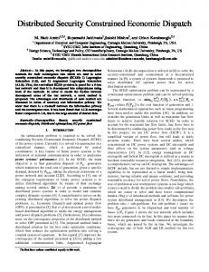
where Vi,mj and Vi M , j are time-varying thresholds fixed to ensure a desirable voltage transient. The adoption of this constraints permits to prevent the system from angle instability as observed in [7, 11]. 3.3 Steady-state constraints Steady-state voltage profile can also be ensured through (9). In this case, it is sufficient to fix proper limits Vi,mj and Vi M , j for steps relative to a time where the system can be considered damped out. Analogously, steady-state constraints on the power transfer limits of major interconnection lines can be imposed as follows: Ti m, j ≤ Ti , j ≤ Ti ,Mj i = n D ,…, n T (10) where n D denotes a time step where transients can be considered sufficiently damped out. The active and reactive power and the voltage magnitude at the generating nodes are subject to limitations due to generators capability curves. 3.4 Protection system inequality constraints In the system under investigation, distance relays are adopted for line protection with some portions of the network characterized by units not equipped with blocking relays. Distance relays adopted by the utility are of the type illustrated in Fig. 1, and are characterized by three trip zones. The protection characteristic, adopted in simulations, is relative to actual relays utilized on the transmission system known as ENERTEC PXLP3000. Note that, in Fig.1 and in following developments, resistance and reactance are in p.u. with regard to the impedance of the line to be protected by the distance relay. For each zone the measurement of the reactance is adopted to evaluate the distance from the fault. The reactance characteristics are restricted by the intersection of two mho units, which limit the trip zone to the region inside the common part of the mho circles. Moreover the relay is supervised by a directional element to prevent tripping due to faults behind the relay. The implementation of dynamic preventive control takes into account the influence of distance relays on the system transient behaviour. In particular, the improper switching of the protection system is avoided by inequality constraints that force swing locus in the R-X plane to keep off the relay characteristic for a period of time sufficient to avoid tripping. These requirements can be expressed in terms of time varying inequality constraints incorporated in the following penalty function:
( Ri , j , X i , j ) ∈ Ω j nT n ∑ ∑ α zj ( X ij − X kj ) 2 if X i , j < X k , j CZk = i = ncl j=1 (11) tk , j > t k , j 0 otherwise k = 1, 2, 3 where: - k denotes protective zones; - αzj weights the contribution of each distance relay with regard to other ones; - X kj is the relay reactance threshold for the k-th zone; - (Ri,j , Xi,j ) is the generic point in the R-X plane reported in Fig. 2; - Ω j is the area common to the two mho units and to directional elements as indicated in Fig. 1; - tk,j is duration which ( Ri , j , X i , j ) ∈ Ω j and X i , j < X kj for; - t k , j is the relay time threshold for each k-th protective zone. In general, relay thresholds are fixed for each j-th line. Note that Ω j can be conservatively increased with regard to the actual area in order to guarantee a security margin to avoid improper switching. From definition of the penalty function CZk, it is evident how the algorithm among other objectives is oriented to avoid improper tripping while assessing preventive control. It is important to point out that the easiness, which the protection system is included among constraints with, is due to the capability of the algorithm in tracking trajectories, generated by a time domain simulator, and bound them across a time varying domain in the space of state variables and voltages.
Figure 1: Distance relay characteristic The choice of relative weights of cost functions is based on some heuristics and knowledge of the system. However it should be pointed out that these weights can be automatically adapted during the iterative process. For example, instability constraints weighting factors
14th PSCC, Sevilla, 24-28 June 2002
4 TEST RESULT The Italian power system data have been used to test the proposed approach. The system is characterized by 614 buses, 630 lines, 220 transformers and 141 generators. Non-linear loads were assumed for both active and reactive power. Synchronous machines were represented with a fourth order detailed model and each generating unit was equipped with a second or a third order model excitation system. For testing purpose only, all lines were equipped with distance relays of the type illustrated in Figure 1. For our tests, we used a DEC ALPHA SERVER 4100/400, CPU type 21164 ALPHA 400 MHz, 4MB L2 cache, 2GB RAM and 16 GB RAID disk space. We tested the algorithm for different loading and topological conditions. In all simulations, the time step was assumed equal to 0.02 s and the optimisation problem was run on a time interval up to 6s. The base case consists in an operating condition obtained from the state estimator of the National Control Centre managed by ENEL S.p.A. at 9.34 a.m. on March 27th , 1996. This operating condition is characterized by a load demand at its daily peak. We considered an overload evenly distributed on the network of 22.5%, the outage of major transmission lines connecting the South to the North Italy (LatinaGarigliano, Popoli-Capriati) and a three-phase fault occurred in the area of Rome (Valmontone-Presenzano) cleared in 0.18s. This burdensome condition has given rise to large swings during the post fault transient phase without yielding directly an unstable case. However, large swings may give rise to improper switching of line Montalto-Villanova. This scenario causes a further overload on line Villanova-Foggia and, finally, the separation of Italy in two islands namely the Northern and Southern part of peninsula, with the consequent loss of synchronism of Southern Italy.
Figure 3 shows how the representation of the protection system plays an important role in judging the stability of the system. The swing curve (a) represents the system behaviour when the representation of distance relays is included in the time domain simulation. It can be observed that the system exhibits an unstable behaviour. 0
-50
rotor angle [deg]
play a leading role during the first iteration when security violations have to be eliminated. Thus, during the first iterations, it is better to increase security-related penalty function weights with regard to the economic objective function CEC.
Session 05, Paper 4, Page 5
-100 (b) -150
(a) -200
-250
-300 0
1
2
3
4
5
6
time [s]
Figure 3: Rotor swing curve at unit Tusciano: (a) with the representation of the distance relay, (b) without the representation of the distance relay. This is due to a cascade event starting with a threephase fault on line Valmontone-Presenzano cleared in 0.18 s followed by an improper tripping of the line Montalto-Villanova at time 2.6 s. Figure 4 shows the swing locus in the R-X plane for a relay installed at the sending end of line MontaltoVillanova located near the tripped line. It is possible to observe how the relay apparent impedance, characterized by a low value of reactance, crosses the release area for a sufficient period of time, causing the trip of the line.
Figure 4: Swing locus in R-X plane before optimisation
Figure 2: Portion of the Italian Power Grid
In the above mentioned Figure 3, it can also be observed that the simulation, carried out without representing the protection system, yields a stable case (swing curve b).
14th PSCC, Sevilla, 24-28 June 2002
Session 05, Paper 4, Page 6
By the implementation of the proposed approach, it is possible to move the swing locus out of the release area avoiding the relay operation as shown in Figure 5.
functions are quadratic and characterized by the following threshold limits: • ∆=120°; • Vm = 0.8 p.u. during transient activity and Vm=0.9 p.u. in steady-state conditions; • VM = 1.2 p.u. during transient activity and VM=1.1 p.u. in steady-state conditions; • Tm = -TM where TM is fixed according to the thermal capacity of a specific transmission line. Thermal limits, angle and voltage constraints are violated at first iteration. Apparent impedance during swings never goes in the first zone according to the null value of the relative cost function CZ1 . Looking at the value of penalty function CZ2 , it is possible to realize that the second zone relay is activated only at the first iteration. It can be observed that the values of CZ3 are different from zero at the first two iteration meaning that the trajectory pass through the third zone relay. At the last iteration the swing locus is out of the third zone too since CZ3 is equal to zero.
Figure 5: Swing locus in R-X plane after the optimisation.
iter # 1 2 3
In Figure 6, the rotor angle at generator Tusciano is shown during the iterative process. Swing curve (a) corresponds to the behaviour of the system before preventive control when improper switching occurs causing an unstable condition, whereas curve (b) denotes the trajectory after rescheduling.
CEC Cδδ [p.u.] [rad 2] 0.0 18.73 0.10 0 0.07 0
CV CT CZ1 CZ2 CZ3 [p.u.] [p.u.] [p.u.] [p.u.] [p.u.] 1.9 4.84*10-4 0.00 1.10*10-3 19.34 0.002 4.18*10-4 0.00 0.00 4.53 0 0 0.00 0.00 0.00
Table I. Convergence behaviour for the optimisation process. Figures 7, 8 show the rescheduling of the generated active and reactive power at selected generating units. Units have been selected considering the ones that experienced the largest deviations.
0
-50
iteration 1
iteration 3
900
-100
800 -150
700
Active Power [MW]
rotor angle [deg]
(b)
-200
(a) -250
-300 0
1
2
3 time [s]
4
5
600 500 400 300 200
6
Figure 6: Rotor swing curves at unit Tusciano: (a) before optimisation; (b) after optimisation.
100 0 627
414
741
982
1084 1009
998
586
665
588
-100
bus number
Table I shows how objective and penalty functions change during the iterative process. It can be remarked that in few iterations, the proposed approach is able to avoid the improper switching of the relay minimizing the real-time control cost CEC. As consequence of this control action an improvement of the transient behaviour of the system can be observed. Rotor angle limits (8), voltage limits (9) and steady-state thermal limits (10) are taken into account by suitable penalty functions named Cδ, CV and CT respectively. Penalty
Figure 7: Rescheduling of the generated active power The comp utational cost of the approach is limited. In fact, the wall clock time for the time domain simulation is equal to 27.5 s whereas 18.9 s are needed to evaluate the Lagrangian multipliers. The average time for a single iteration is equal to 52.3 s. It can be observed that the time needed for a single iteration exceeds the sum of the two main modules since L.F. calculations and output routing have to be considered in the computation time.
14th PSCC, Sevilla, 24-28 June 2002
iteration 1
Session 05, Paper 4, Page 7
6 AKNOWLEDGEMENT
iteration 3
The authors wish to thank the ENEL S.p.A. for providing financial support to this research under grant # RAEXC006/0/00.
Reactive Power [MVAr]
400 350 300
REFERENCES
250 200 150 100 50 0 588
882
665
565
258
456
1007
61
637
998
bus number
Figure 8: Rescheduling of the generated reactive power 5 CONCLUSIONS An optimisation procedure is adopted in this paper for evaluating a preventive control action able to avoid improper switching of distance relays during power swings. The optimisation problem considers the minimisation of an economical objective function in presence of practical inequality constraints. These constraints define domain characterised by viable values of state variables and voltages during transients ensuring correct operation of the protection systems and acceptable transient performances. The optimisation problem is solved by the Reduced Gradient method, which gives rise to a simple software structure compatible with existing software structures available at modern control centers. The procedure tested on an actual power system characteristic with some distance relays without blocking units proves to be effective in avoiding cascade switching during large power swings. A limitation of the approach is that mu ltiple severe contingencies cannot be treated simultaneously. However the approach is prone to integrate this feature exploiting the potentials of parallel/distributed computing and of the mathematical formulation based on the gradient method. Computational time appears compatible with extended real-time requirements.
[1] G.A. Maria, C. Tang, J. Kim, “Hybrid transient stability analysis”, IEEE Trans. on Power Systems, Vol. 5, n. 2, May 1990. [2] C.K. Tang, C.E. Graham, M. El-Kady, R.T.H. Alden, “Transient stability index from conventional time domain simulation”, IEEE Trans. on Power Systems, Vol. 9, n. 3, August 1994. [3] E. Vaahedi, Y. Mansour, A. Y. Chang, B.R. Corns, E.K. Tse, “Enhanched second kick methods for on-line DSA”, IEEE Trans. on Power Systems, Vol. 11, n. 4, Nov. 1996. [4] V. Vittal, T. Oh, A.A. Fouad, “Apparent impedance correlation of transient energy margin and time simulation” IEEE Trans. on Power Systems, Vol. 3, n. 2 May 1988. [5] C. Singh, I. Hiskens, “Direct Assessment of Protection Operation and Non-Viable Transients”, IEEE Trans. on Power Systems, Vol. 16, n. 3, August 2001. [6] F. Dobraca, M.A. Pai, P.W. Sauer, “Relay margins as a tool for dynamical security analysis”, International Journal of Electrical Power and Energy Systems, Vol. 12, n. 4, Oct. 1990. [7] E. De Tuglie, M. La Scala, P. Scarpellini. "Real-Time Preventive Actions for the Enhancement of Voltage-Degraded Trajectories", IEEE Transactions on Power Systems, Volume: 14 Issue: 2 May 1999 Page(s): 561 -568 [8] E. De Tuglie, M. Dicorato, M. La Scala, P. Scarpellini, "Dynamic security control in a deregulated electricity market", Proc. of PSCC, Trondheim, Norway, 1999. [9] GME “Electricity Market Rules”, www.mercatoelettrico.org [10] D. Gan, R. J. Thomas, R. D. Zimmerman, “A Transient Stability Constrained Optimal Power Flow”, Bulk Power System Dynamics and Control IV-Restructuring, August 24-28 1998, Santorini, Greece. [11] A.B.R. Kumar, V. Bdwajn, A. Ipakchi, R. Adapa, “Integrated framework for dynamic security analysis”, Proc. of IEEE of 20th Int. Conf. on Power Industry Computer Applications, pp. 260-265, may 11-16, 1997, Columbus, Ohio.