Hindawi Publishing Corporation Journal of Renewable Energy Volume 2015, Article ID 490178, 14 pages http://dx.doi.org/10.1155/2015/490178
Research Article Dynamic Stability Improvement of Grid Connected DFIG Using Enhanced Field Oriented Control Technique for High Voltage Ride Through V. N. Ananth Duggirala1 and V. Nagesh Kumar Gundavarapu2 1
Department of EEE, Viswanadha Institute of Technology and Management, Visakhapatnam 531173, India Department of EEE, GITAM University, Visakhapatnam, Andhra Pradesh 530045, India
2
Correspondence should be addressed to V. Nagesh Kumar Gundavarapu;
[email protected] Received 25 June 2015; Accepted 29 September 2015 Academic Editor: Shuhui Li Copyright © 2015 V. N. A. Duggirala and V. N. K. Gundavarapu. This is an open access article distributed under the Creative Commons Attribution License, which permits unrestricted use, distribution, and reproduction in any medium, provided the original work is properly cited. Doubly fed induction generator (DFIG) is a better alternative to increased power demand. Modern grid regulations force DFIG to operate without losing synchronism during overvoltages called high voltage ride through (HVRT) during grid faults. Enhanced field oriented control technique (EFOC) was proposed in Rotor Side Control of DFIG converter to improve power flow transfer and to improve dynamic and transient stability. Further electromagnetic oscillations are damped, improved voltage mitigation and limit surge currents for sustained operation of DFIG during voltage swells. The proposed strategy has advantages such as improved reactive power control, better damping of electromagnetic torque oscillations, and improved continuity of voltage and current from stator and rotor to grid during disturbance. In EFOC technique, rotor flux reference changes its value from synchronous speed to zero during fault for injecting current at the rotor slip frequency. In this process, DC-Offset component of stator flux is controlled so that decomposition during overvoltage faults can be minimized. The offset decomposition of flux will be oscillatory in a conventional FOC, whereas in EFOC it is aimed to be quick damping. The system performance with overvoltage of 1.3 times, 1.62 times, and 2 times the rated voltage occurring is analyzed by using simulation studies.
1. Introduction The doubly fed induction generator (DFIG) is preferred due to its small size with higher MVA ratings available in the market, low power ratings of converters, variable generator speed and constant frequency operation, robust fourquadrant reactive power control, and improved performance during the high and low voltage ride through (HVRT and LVRT). However, DFIG is sensitive to external disturbances like voltage swell and sag. If grid voltage falls or rises suddenly due to any reason, large surge currents enter the rotor terminals and induce the voltage significantly. So, the rotor side converter (RSC) gets damaged due to exceeding voltage or the current rating. Apart from this, there will be huge electromagnetic torque pulsations and increase in rotor speed which may reduce burden on gears of the wind turbinegenerator. Such phenomenon reduces lifetime of overall system.
A study of LVRT and HVRT issue for DFIG with rotor current dynamics is given in [1]. In this paper, rotor open and short circuit analysis and differential equations are derived and analyzed to improve the capability of DFIG during disturbances. Hybrid current controllers are used to improve the capability of DFIG to deliver desired reactive power and withstand capability during LVRT and HVRT in [2]. In [3], authors discuss the problems and possible measures to improve performance during HVRT by proposing active voltage control. A fast coordinated control scheme based on the characteristics of DFIG was proposed to improve performance during LVRT and HVRT [4]. Effects of asymmetrical HVRT are analyzed and control strategy for improving performance during overvoltages is done in [5]. A grid side converter (GSC) based control strategy to improve voltage changes in DC link capacitor during HVRT is shown in [6]. FACTS devices like STATCOM [7] and dynamic voltage
2 restorer [8] are used to mitigate voltage swell without phase angle deviation and to investigate HVRT issues. Energy storage devices like SMES to meet the requirement of transmission system operators (TSOs) for wind generation system of HVRT through two grid codes have been discussed in [9]. The critical comparison between HVRT and LVRT is drawn in [10]. The use of active resistance to suppress rotor current and torque oscillations for enhanced operation HVRT is described in [11]. Some external passive elements and active sources are used in conjunction to improve stability and thereby leading to a better LVRT operation of DFIG during symmetrical and asymmetrical faults. Single phase crowbar, supercapacitor energy storage system [12], fault current limiter (FCL) [13], and superconducting FCL with magnetic energy storage devices [14] are connected in coordination with DFIG system to enhance system LVRT behavior during severe faults. The STATCOM [15–22], familiar shunt device from FACTS family, is used to surmount the system to lose synchronism due to external disturbances like large symmetrical and asymmetrical faults, voltage rise, variation in wind speed, and subsynchronous resonance. Two sequence components with dual voltage control during grid faults for DFIG-STATCOM system are used in [22, 23]. The DVR with high temperature superconductor fault current limiter (SCFCL) application is used for controlling balanced and unbalanced grid faults for DFIG [24]. Eigenanalysis with frequency domain approach used for sea-shore wind farm to improve system stability for DFIG and SCIG is discussed in [25] by applying an UPFC controller. The process of energy storage with the help of superconducting coil by integrating it to the DC link back-to-back converters for DFIG system is discussed in [26]. The research on the behavior of DFIG system during HVRT is still in its nascence. There are a few research papers available. As per modern grid codes for the countries like Australia and Spain, DFIG system must withstand to 1.3 times the rated voltage without losing synchronism. It is generally observed that, with sudden increase in grid voltage, stator and rotor voltages increase and current decreases. The electromagnetic torque (EMT) increases when rotor speed decreases. The rotor voltage and current frequency decrease as slip frequency decreases (sf) due to decrease in slip value. The rotor current decrease for DFIG depends on rotor and stator winding parameters, increase in voltage magnitude at grid, and decrease in speed of rotor. If rotor and stator flux change is controlled, EMT, rotor speed, and machine currents can be controlled effectively. To achieve this, the first step is that a new reference synchronous speed has to be chosen based on change in speed during fault. The second step is that DC offset component of flux must be eliminated, oscillations must be damped, and change in magnitude of 𝑞-axis flux components must be controlled. This methodology is termed as enhanced field oriented control (EFOC). The efficacy of EFOC is analyzed for a standard DFIG system for improving voltage and current profile of stator and rotor with stable torque, speed, and flux control mechanism. The system performance with overvoltage at grid terminals during 0.8 to 1.2 seconds with an electromagnetic
Journal of Renewable Energy torque of 200 Nm is analyzed. In the analysis, the grid fault voltage is considered in three cases: case 1, 1.3 times; case 2: 1.62 times; and case 3: 2 times the grid voltage with other parameters remaining constant. The voltage and current parameters at rotor, stator, grid voltage, and DFIG electromagnetic torque (EMT) and speed of the rotor are compared and analyzed for all the three cases. The proposed EFOC method can be applicable to both LVRT and HVRT issues, which help in improving current and voltage profile at stator and rotor terminals during disturbance. Better performance DFIG operation is expected when using EFOC technique in contrast to the conventional FOC method. In addition, there is no need to use robust PIR or any other sophisticated controllers. Generally, when a severe grid overvoltage occurs, oscillations arise with the increase of stator terminal voltage, DC link capacitor voltage increases, speed of rotor decreases, and electromagnetic torque increases. In Section 2, design of converters for EFOC is explained. In Section 3, mathematical modeling of wind turbine and generator converters for the grid connected DFIG is explained during transient state. In this section, effect of system during symmetrical fault, EFOC control technique, and behavior of mechanical and electrical system with variation in rotor speed are explained in subsections. Simulation results are described in Section 4 of overvoltage of 1.3, 1.62, and 2 times the rated voltage in the MATLAB environment. The conclusion is presented in Section 5 followed by the Appendix and References.
2. Design of Rotor Side Converter Control for EFOC RSC controller helps in improving reactive power demand at grid and in extracting maximum power from the machine by making the rotor run at optimal speed. The optimal speed of the rotor is decided from machine’s real power and rotor speed characteristic curves from MPPT algorithm. The stator active and reactive power control is possible with the RSC controller strategy through 𝑖𝑞𝑟 and 𝑖𝑑𝑟 components controlling, respectively. The rotor voltage in a stationary reference frame [11] and further analysis from [27] is given by 𝑉𝑟𝑠 = 𝑉0𝑟𝑠 + 𝑅𝑟 𝑖𝑟𝑠 + 𝜎𝐿 𝑟
𝑑𝑖𝑟𝑠 − 𝑗𝜔𝑖𝑟𝑠 , 𝑑𝑡
(1a)
where 𝜎 = 1 − 𝐿2𝑚 /𝐿 𝑠 𝐿 𝑟 , 𝜔 is the rotor speed, 𝑖𝑟𝑠 is the rotor current in a stationary frame of reference, 𝐿 𝑠 , 𝐿 𝑟 , and 𝐿 𝑚 are stator, the rotor, and mutual inductance parameters in Henry or in pu, and 𝑉0𝑟𝑠 =
𝐿𝑚 𝑑 ( − 𝑗𝜔𝑠 ) Φ𝑠𝑠 𝐿 𝑠 𝑑𝑡
(1b)
is the voltage induced in the stator flux with Φ𝑠𝑠 = 𝐿 𝑠 𝑖𝑠𝑠 + 𝐿 𝑚 𝑖𝑠𝑠 , Φ𝑠𝑟 = 𝐿 𝑟 𝑖𝑟𝑠 + 𝐿 𝑚 𝑖𝑟𝑠 .
(2)
Journal of Renewable Energy
3
The 𝑑- and 𝑞-axis rotor voltage equations ((1a), (1b)) and (2) in the synchronous rotating reference frame are given by 𝑉𝑑𝑟 = 𝑉𝑞𝑟 =
𝑑Φ𝑑𝑟 − (𝜔𝑠 − 𝜔) Φ𝑞𝑟 + 𝑅𝑟 𝑖𝑑𝑟 , 𝑑𝑡 𝑑Φ𝑞𝑟 𝑑𝑡
𝑑𝑖𝑑𝑟 −𝑅𝑟 1 𝑖𝑑𝑟 + 𝑠𝜔𝑠 𝑖𝑞𝑟 + 𝑉 , = 𝑑𝑡 𝜎𝐿𝑟 𝜎𝐿𝑟 𝑑𝑟 (3)
+ (𝜔𝑠 − 𝜔) Φ𝑑𝑟 + 𝑅𝑟 𝑖𝑞𝑟 .
(4)
Φ𝑞𝑠 = (𝐿 𝑙𝑠 + 𝐿 𝑚 ) 𝑖𝑞𝑠 + 𝐿 𝑚 𝑖𝑞𝑟 , where 𝐿 𝑟 = 𝐿𝑙𝑟 + 𝐿 𝑚 , 𝐿 𝑠 = 𝐿𝑙𝑠 + 𝐿 𝑚 , and 𝜔𝑟 = 𝜔𝑠 − 𝜔. By substituting (4) into (3) and by rearranging the terms, then 𝑉𝑑𝑟 = (𝑅𝑟 +
𝑑𝐿𝑟 𝐿 ) 𝑖𝑑𝑟 − 𝑠𝜔𝑠 𝐿𝑟 𝑖𝑞𝑟 + 𝑚 𝑉𝑑𝑠 , 𝑑𝑡 𝐿𝑠
𝑉𝑞𝑟 = (𝑅𝑟 +
𝑑𝐿𝑟 ) 𝑖𝑞𝑟 + 𝑠𝜔𝑠 𝐿𝑟 𝑖𝑑𝑟 𝑑𝑡
+
(5)
𝐿𝑚 (𝑉 − 𝜔Φ𝑑𝑠 ) , 𝐿 𝑠 𝑞𝑠
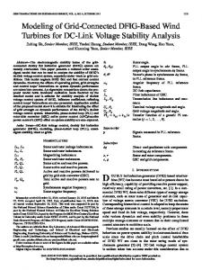
where 𝜔 is rotor speed, 𝜔Φ𝑠 is speed of stator flux, and 𝜔𝑠 is synchronous speed. The MATLAB and SIMULINK based on the control circuit of RSC for enhancing performance for LVRT issues are presented in Figure 1. The right side corner with subsystem 2 is a subcircuit of the controller for EFOC technique and its design is shown later in Figure 5. The above equations (5) can be rewritten in terms of decoupled parameters and are designed for RSC controller as in the following: 𝜎𝑉𝑑𝑟 = 𝜎𝐿𝑟 +
𝑑𝐼𝑑𝑟 − 𝜔𝑠 Φ𝑞𝑟 𝑑𝑡
𝐿𝑚 (𝑉 − 𝑅𝑠 𝐼𝑑𝑠 + 𝜔1 Φ𝑞𝑠 ) , 𝐿 𝑠 𝑑𝑠
𝜎𝑉𝑞𝑟 = 𝜎𝐿𝑟
𝑑𝐼𝑞𝑟 𝑑𝑡
+ 𝜔𝑠 Φ𝑑𝑟 −
𝐿𝑚 (𝑅𝑠 𝐼𝑞𝑠 + 𝜔1 Φ𝑑𝑠 ) . 𝐿𝑠
=
2 1 −1 𝑅𝑟 𝑅𝑠 𝐿𝑚 𝑉 . ( + 2 ) 𝑖𝑞𝑟 − 𝑠𝜔𝑠 𝑖𝑑𝑟 + 𝜎 𝐿 𝑟 𝐿 𝑠𝐿 𝑟 𝜎𝐿𝑟 𝑞𝑟
(8a) (8b)
The reference rotor voltages in 𝑑𝑞 transformation can be rewritten from (6) and (7) and from the control circuit from Figure 1 are given below. This is the output voltage from rotor windings during normal and transient conditions:
Φ𝑑𝑟 = (𝐿 𝑙𝑟 + 𝐿 𝑚 ) 𝑖𝑑𝑟 + 𝐿 𝑚 𝑖𝑑𝑠 ,
Φ𝑑𝑠 = (𝐿 𝑙𝑠 + 𝐿 𝑚 ) 𝑖𝑑𝑠 + 𝐿 𝑚 𝑖𝑑𝑟 ,
𝑑𝑖𝑞𝑟 𝑑𝑡
The stator and rotor two-axis fluxes are
Φ𝑞𝑟 = (𝐿 𝑙𝑟 + 𝐿 𝑚 ) 𝑖𝑞𝑟 + 𝐿 𝑚 𝑖𝑞𝑠 ,
back emf and rotor speed. The transient rotor 𝑑𝑞-axis current is given by
(6)
(7)
In this paper, the rotor speed is represented with 𝜔𝑟 and the synchronous speed of stator is with 𝜔𝑠 . But this synchronous frequency has to be changed from 𝜔𝑠 to a new synchronous speed value as described in flowchart in Figure 4, 𝜔𝑠 as it is represented commonly by 𝜔1 . Under ideal conditions, reference stator 𝑑-axis flux Φ∗𝑑 is zero and 𝑞-axis flux Φ∗𝑞 is equal to the magnitude of stator flux Φ𝑠 for given
∗ ∗ = (𝑖𝑑𝑟 + 𝑉𝑞𝑟
2 1 𝑅𝑟 𝑅𝑠 𝐿𝑚 ( + 2 ) 𝑖𝑞𝑟 + 𝑠𝜔𝑠 𝑖𝑑𝑟 ) 𝜎𝐿𝑟 , 𝜎 𝐿 𝑟 𝐿 𝑠𝐿 𝑟
(9a)
∗ ∗ = (𝑖𝑑𝑟 + 𝑉𝑞𝑟
2 1 𝑅𝑟 𝑅𝑠 𝐿𝑚 ( + 2 ) 𝑖𝑞𝑟 + 𝑠𝜔𝑠 𝑖𝑑𝑟 ) 𝜎𝐿𝑟 . 𝜎 𝐿 𝑟 𝐿 𝑠𝐿 𝑟
(9b)
The overall block diagram of RSC is presented in Figure 2(a). The rotor speed is multiplied with pole numbers and is subtracted from angular grid synchronous frequency. It is integrated and given a 90∘ phase shift to get rotor slip injection frequency angles (𝜃𝑠 ). At this slip frequency, RSC converter injects current into the rotor circuit to control the rotor speed for optimum value and to control grid reactive power. The stator voltage magnitude is compared and controlled using PI or IMC controller to get 𝑞-axis current. Similarly, rotor actual speed and optimal speed reference are controlled using PI or IMC to get 𝑑-axis reference current. They are compared with actual rotor 𝑑- and 𝑞-axis currents and controlled with tuned PI controllers to get the rotor injecting 𝑑- and 𝑞-axis voltages. The 𝑑 and 𝑞 voltages are converted into three-axis abc voltage by using phase locked loop (PLL) with inverse parks transformation and are given to a PWM pulse generator for getting pulses to RSC converter. The 𝑑-axis decoupled voltage derivation block diagram is shown in Figure 2(b). The 𝑑- and 𝑞-axis stator flux and stator flux magnitude derivation block diagram is shown in Figure 2(c). The flux derivation technique helps in understanding the operation of DFIG during steady state and transient state. The accuracy of system performance during steady state depends on accuracy of wind speed measurement, action of pitch angle controller, instantaneous values of stator and rotor voltage, current, flux, and other parameters. The more accurate these measurements are, the more the real power can be extracted from DFIG wind turbine system. The equations from ((8a) and (8b)) to (11) play a vital role in understanding the behavior of DFIG during steady state and accuracy of RSC control action depends on control of 𝑑- and 𝑞-axis voltages.
3. Mathematical Analysis of RSC and GSC Converters for the Grid Connected DFIG during Transient State 3.1. Three-Phase Symmetrical Faults. The stator voltage will reach zero magnitude during severe three-phase symmetrical
4
Journal of Renewable Energy Wr∗ + − Wr
+
PI
+
PI
Iqr −
+ −
Wr
+
Lm Ls
−1
+
W𝜆s
+
X
X 0.1 Vqs
Idr
∗ Vqr
∗ Vdr
−
+
dq to
PWM
abc
RSC pulses
𝜆dr Wr
Vs = 1
+
+
PI
+
PI
+
−
−
+
Idr
Vs
W𝜆s
+
−1 −
Wr
+ Lm V L s qs
X
0.1 Iqr
Figure 1: The RSC controller with EFOC technique design for grid connected DFIG.
fault of very low impedance and stator flux Φ𝑠 gets reduced to zero magnitude. The decay in flux is not as rapid as in voltage and can be explained from the flux decay theorem from past observations and further can be explained as delay is due to inertial time lag 𝜏𝑠 = 𝐿 𝑠 /𝑅𝑠 affecting the rotor induced Electromotive Force (EMF) 𝑉0𝑟 . The flux during fault is given by Φ𝑠𝑠𝑓 = Φ𝑠𝑠 𝑒−𝑡/𝜏𝑠
(10)
and 𝑑Φ𝑠𝑠𝑓 /𝑑𝑡 is negative, indicating its decay. By substituting (10) into (1b), 𝑉0𝑟𝑠 = −
𝐿𝑚 1 ( + 𝑗𝜔) Φ𝑠𝑠 𝑒−𝑡/𝜏𝑠 . 𝐿 𝑠 𝜏𝑠
(11)
The above equation is converted into a rotor reference frame and neglecting 1/𝜏𝑠 𝑉0𝑟𝑠 = −
𝐿𝑚 (𝑗𝜔) Φ𝑠𝑠 𝑒−𝑗𝜔𝑡 . 𝐿𝑠
(12)
By substituting Φ𝑠𝑠 = (𝑉𝑠𝑠 /𝑗𝜔𝑠 )𝑒−𝑗𝜔𝑠 𝑡 into (12), 𝑉0𝑟𝑟 = −
𝐿𝑚 (1 − 𝑠) 𝑉𝑠 . 𝐿𝑠
(13)
|𝑉0𝑟𝑟 | is proportional to (1 − 𝑠). Converting equation (1a) into the rotor reference frame 𝑑𝑖𝑟𝑟 (14) . 𝑑𝑡 Thus, rotor equivalent circuit derived from (12) is as shown in Figure 3 [11]. From equivalent circuit in Figure 3, the rotor voltage during fault is given by 𝑉𝑟𝑟 = 𝑉0𝑟𝑟 𝑒−𝑗𝜔𝑡 + 𝑅𝑟 𝑖𝑟𝑟 + 𝜎𝐿 𝑟
𝑉𝑟 = 𝑖𝑟 𝑅𝑟 + 𝜎𝐿𝑟
𝑑𝑖𝑟 + 𝑉𝑜𝑟 𝑑𝑡
(15a)
or 𝑉𝑟 = 𝑖𝑟 𝑅𝑟 + 𝜎𝐿𝑟
𝑑𝑖𝑟 𝐿 𝑚 𝑑Φ𝑠 + . 𝑑𝑡 𝐿 𝑠 𝑑𝑡
(15b)
In (15b), the first two terms on RHS determine the voltage drop by rotor current due to passive elements and the last term determines the EMF induced by the stator flux. A considerable decrease in prefault steady state voltage 𝑉0𝑟𝑟 to a certain fault voltage during a three-phase fault is explained here. However, RSC converter is designed to meet 𝑉𝑟𝑟 to match 𝑉0𝑟𝑟 for rotor current control and the design has to be made for rating of only 35% of stator rated voltage. The voltage dip during fault can be adopted independently or in coordination by using two techniques as explained in Figure 3. During fault, at first instant, Φ𝑠 does not fall instantly (12) as shown in the flux and voltage trajectories [27]. If the machine is running at super synchronous speed with slip (𝑠) near to −0.2 pu, during fault, rotor speed further increases based on the term (1 − 𝑠) as given by (12). The above speed change is uncontrollable for a generator having higher electrical and mechanical inertia constants. In order to control the rotor current change, 𝑉𝑟𝑟 has to be increased. Based on the first reason, a voltage 𝑉Φ𝑠 has to be injected in the feed forward path for improving the rotor dip to reach its near steady state value. By converting (12) into a synchronous reference frame and by considering direct alignment of Φ𝑑𝑠 with Φ𝑠 , we get 𝑉Φ𝑠 = −
𝐿𝑚 𝜔Φ𝑑𝑠 . 𝐿𝑠
(16)
The second technique for voltage increase requirement in a rotor is that dip can be compensated by replacing 𝑠𝜔𝑠 with (𝜔Φ𝑠 − 𝜔) in cross coupling terms 𝑠𝜔𝑠 𝐿𝑟 𝑖𝑞𝑟 and 𝑠𝜔𝑠 𝐿𝑟 𝑖𝑑𝑟 , respectively. The reduction in magnitude and frequency of
Journal of Renewable Energy
5 𝜃s
𝜔r
P
+
PI
𝜔∗r 𝜔r
+
Idr PI
−
Iqr
+
𝜎Lr
idr iqr
Rr
→r
ir ← +
sin_cos cos +
𝜎Vdr
+
abc/ dq
sin
PI
−
iabcr
+ 𝜋 2
−
Vs
+
1 s
+
2𝜋f Vs∗
−
→r
+ +
PI
− 𝜎Vqr
Vr
−
to +
→r
V 0r
dq PWM
RSC
abc
−
+
Figure 3: The rotor equivalent circuit.
(a) Complete RSC controller design
L2m − Lr Ls
(𝜔s − 𝜔r )
𝜎Vdr
idr (b) Block diagram representation of decoupled 𝑑-axis rotor voltage parameter
Vds ids
+ rs
Φds
1 s
− +
Φs = √Φ2ds + Φ2qs
𝜔s
− iqs Vqs
rs
1 s
−
Φqs
+ (c) Block diagram representation of stator flux calculation
Figure 2: Enhanced FOC control technique with the PI controller adopted for RSC.
flux Φ𝑠 and alignment of flux with the stator voltage without the rate of change in flux angle 𝜃Φ𝑠 indicate DC offset component in flux: 𝑑Φ𝑠 = 𝜔Φ𝑠 = 0 = 𝜔𝑓 . 𝑑𝑡
(17)
Here, 𝜔𝑓 is the speed of stator flux during fault and this value can be made to zero as offset. The voltage injection components from equation (16) and (17) and compensating component as discussed above are estimated using enhanced flux oriented control (EFOC scheme whose flowchart is shown in Figure 4 and the determined values are incorporated in the RSC controller shown in Figure 1): 𝑑Φ𝑠 = 𝜔Φ𝑠 = 𝑑𝑡
𝑉𝛽𝑠 Φ𝛼𝑠 − 𝑉𝛼𝑠 Φ𝛽𝑠 Φ2𝛼𝑠 + Φ2𝛽𝑠
When dynamic stability has to be improved, proposed technique controls the decrease in stator and rotor flux magnitude and also damps oscillations at the fault instances. To achieve better performance during transients, this paper proposes a strategy to change stator frequency reference to zero or other values depending on type and severity of disturbance. The accurate measurement of stator and rotor parameters like flux and current helps in achieving better performance during transients. The DC offset stator current reduction during transients and making the two-axis flux and voltage trajectory circular also improves the efficacy of the system performance during any faults. The equations (7) to (12) help in understanding DFIG behavior during transient conditions and accuracy of its working depends on measurement of rotor current and flux parameters. 3.2. EFOC Technique. The EFOC method of improving field flux oriented control technique helps in improving the performance of the RSC controller of DFIG during fault conditions as described in Figure 4. The DCOC observer carries two actions: the change in flux values of stationary frame stator references (Φ𝛼𝑠 , Φ𝛽𝑠 ) for tracking radius of trajectory and DCOC for offset change in stationary fluxes (Φ𝑑𝑐𝛼𝑠 , Φ𝑑𝑐𝛽𝑠 ) during fault conditions and controlling them. There are two major controlling actions with proposed EFOC technique. The first action helps in gaining the trajectory of a circle point and helps in reaching its pre-fault state with the same radius and center of the circle. This helps in improving and maintaining the same rate of change in flux compensation even during fault without losing the stability. The second action helps in controlling and maintaining to nearly zero magnitude of EMF in DFIG with the action of (DC offset component) DCOC technique. Based on the above two actions, if the former one is greater with change in trajectory which generally happens during disturbances from an external grid, stator synchronous frequency flux speed (𝜔Φ𝑠 ) changes to synchronous grid frequency flux (𝜔𝑠 ); otherwise, 𝜔Φ𝑠 changes to fault angular frequency value and is injected to RSC voltage control loop as error compensator. The general form of speed regulation is given by 𝑇𝑒 = 𝐽
= 𝜔𝑓 .
(18)
𝑑𝜔𝑟 + 𝐵𝜔𝑟 + 𝑇𝑙 , 𝑑𝑡
𝑇𝑒 = (𝐽𝑠 + 𝐵) 𝜔𝑟 + 𝑇𝑙 ,
(19a) (19b)
6
Journal of Renewable Energy
Start Calculate 𝜃rs with
Calculate the instantaneous difference (VRYBs − Rs IRYBs )
phase locked loop Flux in 𝛼𝛽 → dq transformation
Apply Clark’s transformation to get V𝛼s , V𝛽s
Calculate Φds
Integrate and obtain Φ𝛼s , Φ𝛽s
Calculate RΦs = √Φ2𝛼s + Φ2𝛽s Calculate DCOC = √Φ2dc𝛼s + Φ2dc𝛽s
If RΦs > DCOC Under steady state, the rotor synchronizing speed will be to improve flux decay and mitigate voltage and current during faults
Under fault conditions, rotor synchronizing
No
Yes
𝜔Φs = 𝜔f
𝜔Φs = 𝜔s
Incorporate 𝜔Φs and Φds in RSC
Stop
Figure 4: Scheme of enhanced flux oriented control, where DCOC = dc offset component of flux and 𝑅B𝑠 = radius of flux trajectory.
Vabcg
+
LPF
𝛼𝛽
− Iabcg
LPF
1/s 1/s
abc
180∘ /𝜋
a tan2
𝜃𝜆
z 𝜆dp [u(4) ∗ u(1)] + [u(3) ∗ u(2)] sin
𝜃𝜆
−[u(3) ∗ u(1)] + [u(4) ∗ u(2)]
𝜆qs
cos
[u(4) ∗ u(1)] + [u(3) ∗ u(2)] |U| |U| −[u(3) ∗ u(1)] + [u(4) ∗ u(2)] Vdse
sin cos
V2
+
V2
+
𝜃𝜆 Ws
if u(1) > u(2) Else 0 or Ws Wf Merge Ws 𝜆s Merge
Vqse
Figure 5: EFOC control loop design with DCOC and rotor flux trajectory control.
where 𝑇𝑒 is electromagnetic torque, 𝐽 is moment of inertia, 𝐵 is friction coefficient, and 𝑇𝑙 is considered to be disturbance. Multiplying both sides with 𝜔error , we get the equation as follows:
Considering 𝜔𝑟 is constant and change in speed error 𝜔error is control variable, the above equation becomes
𝑇𝑒 𝜔error = (𝐽𝑠 + 𝐵) 𝜔𝑟 𝜔error + 𝑇𝑙 𝜔error .
𝑃𝑠∗ = (𝐾𝑖𝑛 𝑠 + 𝐾𝑝𝑛 ) 𝜔error + 𝑃𝑙 .
(20)
(21)
Journal of Renewable Energy
7
As product of torque and speed is power, we will be getting stator reference power and disturbance power as shown in the following: 𝑃𝑠∗ − 𝑃𝑙 = (𝐾𝑖𝑛 𝑠 + 𝐾𝑝𝑛 ) 𝜔error ,
(22)
where 𝐾𝑖𝑛 = 𝐽 ∗ 𝜔𝑟 and 𝐾𝑝𝑛 = 𝐵 ∗ 𝜔𝑟 . Finally, direct axis reference voltage can be written by using (22) and from Figure 4 is ∗ = − (𝜔error ) (𝐾𝑝𝑛 + 𝑉𝑟𝑑 ∗ = 𝑄error (𝐾𝑝𝑄 + 𝑉𝑟𝑞
𝐾𝑖𝑛 𝐾 ) + (𝑃𝑠 ) (𝐾𝑝𝑡 + 𝑖𝑡 ) , 𝑠 𝑠
𝐾𝑖𝑄 ), 𝑠
(23) (24)
∗ ∗ ∗ 𝑉𝑔𝑑 = 𝐾𝑔𝑝 (𝑖𝑔𝑑 − 𝑖𝑔𝑑 ) + 𝑘𝑔𝑖 ∫ (𝑖𝑔𝑑 − 𝑖𝑔𝑑 ) 𝑑𝑡
(25)
− 𝜔𝑜 𝐿 𝑔 𝑖𝑔𝑑 + 𝑘1 𝑉𝑠𝑑 , ∗ 𝑉𝑔𝑞
=
∗ 𝐾𝑔𝑝 (𝑖𝑔𝑞
− 𝑖𝑔𝑞 ) +
∗ 𝑘𝑔𝑖 ∫ (𝑖𝑔𝑞
− 𝑖𝑔𝑞 ) 𝑑𝑡 + 𝜔𝑜 𝐿 𝑔 𝑖𝑔𝑑
𝜆= (26)
+ 𝑘2 𝑉𝑠𝑞 , ∗ 2∗ 2 ∗ 𝑖𝑔𝑞 = 𝐾𝑞 𝑠𝑞𝑟𝑡 (𝑉𝑑𝑐 − 𝑉𝑑𝑐 ) + 𝑘𝑞𝑖 ∫ (𝑉𝑑𝑐 − 𝑉𝑑𝑐 ) 𝑑𝑡
(27)
+ 𝑅𝑑𝑐 𝑉𝑑𝑐 , ∗ = 𝐾𝑑 𝑠𝑞𝑟𝑡 (𝑉𝑠2∗ − 𝑉𝑠2 ) + 𝑘𝑑𝑖 ∫ (𝑉𝑠∗ − 𝑉𝑠 ) 𝑑𝑡. 𝑖𝑔𝑑
(28)
The rotating direct and quadrature reference voltages of rotor are converted into stationary 𝑎𝑏𝑐 frame parameters by using inverse parks transformation. Slip frequency is used to generate sinusoidal and cosine parameters for inverse parks transformation. In general, during fault and after fault, the DC link voltage across the capacitor at the DFIG back-to-back converter terminal falls and rises and the STATCOM helps in improving the operation and assists in regaining its voltage value, respectively, to get ready for the operation during next fault. However, STATCOM provides efficient support to the grid-generator system under severe faults by fast action in controlling reactive power flow to grid by maintaining the DC link voltage at the capacitor terminal of DFIG converters constant particularly during transient state. Hence, it helps in improving the dynamic stability of the overall system. 3.3. Behavior of Mechanical and Electrical System with the Variation in Rotor Speed during Faults. The mechanical to electrical relationship is explained as follows. The rotor speed can be expressed as 𝜔𝑟 = (1 − 𝑠) 𝜔𝑠 = 𝑝𝜂𝜔𝜔𝑡 ,
in (27). When rotor speed varies, reference quadrature axis current changes; thereby, current flow in the rotor circuit varies. The stator output also varies with variation in wind turbine speed and DFIG output power. When slip varies, the voltage in rotor circuit also varies which can be explained as per (6) and (7). Further change in rotor voltage leads to change in rotor current; thereby, rotor power flow also varies. When a disturbance like symmetrical fault occurs, rotor speed increases so as to compensate the change in electrical power and the mechanical power. During faults, rotor of DFIG tries to accelerate and reaches a new operating point. Hence the rotor speed decreases with over voltage fault and decreases with under voltage fault. This statement can be understandable from the equal area criterion theory for electrical machines. The mechanical turbine tip speed ratio (TSR) can be written in terms of radius of turbine wings (𝑅), angular stator speed (𝜔𝑠 ), pole pairs, and gear box ratio as
(29)
where 𝑠 is slip of DFIG, 𝑝 is pair of poles of DFIG, 𝜂 is gear box ratio, and 𝜔𝜔𝑡 is wind turbine speed. With the change in wind speed and depending on gears ratio and number of field poles, how the rotor speed varies is shown
𝑅𝜔𝑠 (1 − 𝑠) . 𝑝𝜂V𝑤
(30)
With the increase in stator or grid frequency, TSR increases and vice versa. Similarly, with increase in rotor speed or wind speed, TSR decreases and vice versa. Hence, when an electrical system gets disturbed, mechanical system also gets some turbulence and electrical to mechanical system is tightly interlinked. The steady state behavior of overall system must satisfy the following relation: Δ𝑃 =
−𝑃𝜔𝑡 − 𝑃𝑒𝑚 = 0. (1 − 𝑠)
(31)
Under normal conditions, the change in turbine output has to be compensated by electrical power output from DFIG. Otherwise, slip gets changed and thereby rotor speed changes. Hence, with imbalance in mechanical to electrical power output ratios, the slip changes. With the change in coefficient of power Cp, the mechanical power varies. The mechanical power changes mostly when wind speed or air density around the turbine wings changes. The electrical power from DFIG changes when mechanical power changes or rotor speed changes or load demand from grid varies.
4. Result Analysis In this paper, a general system was considered as shown in Figure 6. The DFIG is driven by a wind turbine and electric power from the generator is pumped to the grid for meeting different loads requirement. The RSC is designed with EFOC technique to enhance operation during grid fault and has better dynamic stability features than a conventional FOC. The role of RSC is to extract maximum power from wind turbine, so the generator is made to rotate at that optimal speed by adjusting gear wheels between generator and turbine shaft. Another role of RSC is to improve the reactive power requirement during any abnormal situations like undervoltage or overvoltage faults. The excess reactive power is supplied by RSC using the capacitor bank at RSC end and accuracy and fastness depend on the control strategy.
8
Journal of Renewable Energy DFIG-WT Stator terminal set
Overvoltage Grid Grid terminal fault T/L equivalent
RSC
GSC
Rotor terminal
Choke coil GSC terminal
Figure 6: Grid connected DFIG showing the location of overvoltage fault.
The GSC of DFIG has two main functions. One function is to maintain nearly constant voltage profile at DC link capacitor so that voltage at point of common coupling (PCC) will also have the same value. The other function is to supply or absorb rapidly required reactive power. The GSC is also designed to bypass surge current to the converter terminal and store in capacitor bank and to reinject the excess power when fault gets relieved. In doing so, the fault current cannot reach stator and rotor and as a consequence GSC protects the two windings of the generator. For the system in Figure 6, voltage swell is expected during the time 0.8 to 1.2 seconds. Swell in voltage occurs when generation is more than load or when a big load is switched off or during lightning. In this, grid voltage, electromagnetic torque, speed, stator and rotor two-axis fluxes and current, and three-phase stator and rotor current are analyzed and compared when grid voltage rises to 1.3, 1.62, and 2 times the rated voltage. The results with HVRT can be compared with [1, 2] for the performance when 1.3 times increase in grid voltage. The rated grid voltage is 270 volts, electromagnetic torque (EMT) is −200 Nm, 2660 rpm speed, 0.05 and −0.75 Weber of stator 𝑑- and 𝑞-axis flux. 0.51 and −0.55 Wb of rotor flux, −40 and −142 Amps of 𝑑 and 𝑞 axis stator current, 130 and 20 Amps of rotor two axis current and 110 Amps of stator and rotor current under steady state conditions respectively. As shown in Figure 7(a)(i), the grid voltage has been increased from 270 volts to 350 volts, which are 1.3 times the rated voltage, and 437 volts’ and 540 volts’ rises during 0.8 to 1.2 seconds are shown in Figure 7(a)(ii) and (iii). For all the three rises in voltage, behavior of DFIG is analyzed. As per modern grid codes, DFIG needs to be in synchronism for 1.3 times’ rise in voltage, but the proposed system is analyzed with twice the rise in voltage. With increase in voltage to 1.3, 1.62, and 2 times, the changes in stator and rotor 𝑑- and 𝑞-axis fluxes are shown in Figure 7(b)(i), (ii), and (iii). A sudden increase in grid voltage leads to large inrush current into the stator and rotor initially. As a result, active power from rotor also increases and reaches the DC link capacitor. Since GSC is of very low rating (35% of rated machine rating), it is not having that ability to transfer current to grid [2, 16, 17]. Hence, in this case, DC capacitor rating if not high enough will get damaged and, overall, the system will lose ride through capability. In our proposed
theory, as explained in Section 3.1, the change in flux with DC offset components and change in speed is detected initially. The flux is controlled by selecting a new rotor speed and the flux further controls the change in voltage and current in rotor circuit by RSC control scheme as explained in flowchart. Thereby, damping of oscillations is eliminated and stability can be enhanced. The more voltage changes, the more magnitude of 𝑞-axis flux will be produced and 𝑑-axis flux will be reduced because flux linkage is proportional to stator and rotor voltages. When voltage is increased to 1.3 times in Figure 7(a)(i), 𝑞-axis stator flux changed from −0.75 to −0.9 Wb during fault and reaches again −0.75 Wb. The rotor 𝑞-axis flux is varied from prefault of −0.55 Wb to −0.9 Wb during fault at 0.8 s and reaches its prefault when fault was cleared at 1.2 s. In the same way, 𝑞-axis stator flux changed to −1.1 and −1.4 Wb with 1 and 2 oscillations and 𝑞-axis rotor flux change is −1 and −1.45 Wb for voltage rise of 1.62 and 2 times with much controlled oscillations as shown in Figure 7(b)(ii) and (iii). Even with voltage rise of two times also, system is highly stable with sustained oscillations in fluxes. The result from proposed scheme has better performance than the results obtained from [1–8] with additional FACTS devices. With 1.3 times rise in voltage as shown in Figure 7(c)(i), torque rises from −200 Nm to −380 Nm when fault started and was maintained to −200 Nm during fault and reached normal value when fault was cleared. Speed of rotor decreased to 2400 rpm from 2660 rpm and was maintained at the same speed during fault and reached its prefault state when fault was cleared. From (9a) and (9b), when flux and current increase, torque will also increase. But with sustained increase in stator and rotor 𝑞-axis flux and decrease in 𝑑-axis flux with enhanced flux control scheme in RSC, helps in reaching its prefault state torque value. Since flux is having very less oscillations, torque is also having limited oscillations. With change in voltage to 1.62 and 2 times, surge in torque is nearly −580 Nm and −1000 Nm when fault was initiated as in Figure 7(c)(ii) and (iii). It is due to surge increase in magnitude of stator and rotor 𝑞-axis fluxes. The 𝑑-axis stator surge current increased in magnitude from −40 A to −90 A, −150 A, and −220 A during voltage increase to 1.3, 1.62, and 2 times as shown in Figure 7(d)(i, ii, and iii) when fault started. The 𝑞-axis stator current increased from −140 A to −180, −200, and −220 A during 1.3, 1.62, and
0 0.5 1 1.5 2 2.5 3 3.5 ×10⁴ Time (ms) (i)
0 0.5 1 1.5 2 2.5 3 3.5 ×10⁴ Time (ms) fId stator fIq stator
0.6 0.4 0.2 0 −0.2 −0.4 −0.6 −0.8 −1 −1.2 −1.4
dq-aix rotor flux (wb)
1
0 0.5 1 1.5 2 2.5 3 3.5 ×10⁴ Time (ms)
Torque (Nm)
Torque (Nm)
3000
Electromagnetic torque (Nm)
0 0.5 1 1.5 2 2.5 3 3.5 ×10⁴ Time (ms) Speed of generator rotor (rpm)
Speed (rpm)
Speed (rpm)
(a) dq-aix stator flux (wb)
1500 1000
−0.5 −1 −1.5 −2
0 0.5 1 1.5 2 2.5 3 3.5 ×10⁴ Time (ms) fId stator fIq stator dq-aix rotor flux (wb)
1.5
dq-aix rotor flux (wb)
1
Flux (Wb)
0 −0.5 −1
0 0.5 1 1.5 2 2.5 3 3.5 ×10⁴ Time (ms) fId rotor fIq rotor (ii)
(b) Electromagnetic torque (Nm)
200
0 0.5 1 1.5 2 2.5 3 3.5 ×10⁴ Time (ms) fId rotor fIq rotor (iii) Electromagnetic torque (Nm)
0 −200 −400 −600 −800 0 0.5 1 1.5 2 2.5 3 3.5 ×10⁴ Time (ms) Speed of generator rotor (rpm)
−1000
3000
0 0.5 1 1.5 2 2.5 3 3.5 ×10⁴ Time (ms) Speed of generator rotor (rpm)
2500
2000 1500 1000 0
0 0.5 1 1.5 2 2.5 3 3.5 ×10⁴ Time (ms) fId stator f fIq stator
0.5
−1.5
0
dq-aix stator flux (wb)
0
−1.5
500
0 0.5 1 1.5 2 2.5 3 3.5 ×10⁴ Time (ms) (iii)
0.5
−1
500 0 0.5 1 1.5 2 2.5 3 3.5 ×10⁴ Time (ms) (i)
−200
1
2500
2000
0
−600
0 0.5 1 1.5 2 2.5 3 3.5 Time (ms) ×104 (ii)
−0.5
3000
2500
200
−400
0
200 100 0 −100 −200 −300 −400 −500 −600
Grid 3-phase voltages
400
0.5
fId rotor fIIq rotor (i)
200 100 0 −100 −200 −300 −400 −500
600
Torque (Nm)
1 0.8 0.6 0.4 0.2 0 −0.2 −0.4 −0.6 −0.8 −1
Flux (Wb)
0.6 0.4 0.2 0 −0.2 −0.4 −0.6 −0.8 −1 −1.2
dq-aix stator flux (wb)
Grid 3-phase voltages
Voltage (V)
Voltage (V)
500 400 300 200 100 0 −100 −200 −300 −400 −500
Flux (Wb)
Grid 3-phase voltages
Speed (rpm)
Flux (Wb)
9
Flux (Wb)
400 300 200 100 0 −100 −200 −300 −400
Flux (Wb)
Voltage (V)
Journal of Renewable Energy
2000 1500 1000 500
0 0.5 1 1.5 2 2.5 3 3.5 ×10⁴ Time (ms) (ii) (c)
Figure 7: Continued.
0
0 0.5 1 1.5 2 2.5 3 3.5 ×10⁴ Time (ms) (iii)
Journal of Renewable Energy
Current (A) Current (A) Current (A)
0 0.5 1 1.5 2 2.5 3 3.5 ×10⁴ Time (ms) Rotor current (A)
(f)
Stator current (A)
250 200 150 100 50 0 −50 −100 −150 −200 −250
d-axis flux (Wb) (iii)
0.8
0.6
Stator dq-axis flux (wb)
0.4
0 −0.2 −0.4 −0.6 −0.8 −1 −1.2 −1.4 −1.6 −1.8 −2
0 0.5 1 1.5 2 2.5 3 3.5 ×10⁴ Time (ms) (iii)
0.2
150 100 50 0 −50 −100 −150 −200 −250
0
(e) Stator dq-axis flux (wb)
Figure 7: Continued.
0 0.5 1 1.5 2 2.5 3 3.5 ×10⁴ Time (ms) Id rotor Iq rotor (iii)
0 0.5 1 1.5 2 2.5 3 3.5 ×10⁴ Time (ms) Rotor current (A) 200
0 0.5 1 1.5 2 2.5 3 3.5 ×10⁴ Time (ms) (ii)
d-axis flux (Wb) (ii)
0 0.5 1 1.5 2 2.5 3 3.5 ×10⁴ Time (ms) Id stator Iq stator dq-axis rotor current (A)
−0.2
0 −0.2 −0.4 −0.6 −0.8 −1 −1.2 −1.4
(d) Stator current (A)
Current (A)
200 150 100 50 0 −50 −100 −150 −200
0 0.5 1 1.5 2 2.5 3 3.5 ×10⁴ Time (ms) Id rotor Iq rotor (ii)
250 200 150 100 50 0 −50 −100 −150
dq-axis stator current (A)
−0.4
0.5
q-axis flux (Wb) d-axis flux (Wb) (i)
0.4
0.3
0.2
0
0.1
0 −0.2 −0.4 −0.6 −0.8 −1 −1.2 −1.4
Stator dq-axis flux (wb)
200 150 100 50 0 −50 −100 −150 −200
0 0.5 1 1.5 2 2.5 3 3.5 ×10⁴ Time (ms) Id stator Iq stator dq-axis rotor current (A)
150 100 50 0 −50 −100 −150 −200 −250
−0.6
0 0.5 1 1.5 2 2.5 3 3.5 ×10⁴ Time (ms) (i)
250 200 150 100 50 0 −50 −100 −150
dq-axis stator current (A)
q-axis flux (Wb)
Current (A)
0 0.5 1 1.5 2 2.5 3 3.5 ×10⁴ Time (ms) Rotor current (A)
150 100 50 0 −50 −100 −150 −200
−0.4 −0.3 −0.2 −0.1 0 0.1 0.2 0.3 0.4 0.5
Current (A) Current (A)
Stator current (A)
−0.1
150 100 50 0 −50 −100 −150 −200
0 0.5 1 1.5 2 2.5 3 3.5 ×10⁴ Time (ms) Id rotor Iq rotor (i)
−0.2
200 150 100 50 0 −50 −100 −150 −200
0 0.5 1 1.5 2 2.5 3 3.5 ×10⁴ Time (ms) Id stator Iq stator dq-axis rotor current (A)
Current (A)
200 150 100 50 0 −50 −100 −150
dq-axis stator current (A)
−0.3
Current (A) Current (A) Current (A)
150 100 50 0 −50 −100 −150 −200
q-axis flux (Wb)
Current (A)
10
Journal of Renewable Energy
−0.6
1
0.8
0.6
−0.8
1
0.8
0.6
0.4
0
0.2
−0.2
−0.4
−0.6
−1.2
−0.8
−1
−1
0.4
−0.8
−0.8
0
−0.6
−0.4
0.2
−0.4
−0.2
−0.2
−0.2
−0.4
q-axis flux (Wb)
0
q-axis flux (Wb)
0
0.2 q-axis flux (Wb)
Rotor dq-axis flux (wb)
0.2
0.2 0 −0.2 −0.4 −0.6 −0.8 −1 −1.2 −1.4 −1.6
Rotor dq-axis flux (wb)
−0.8 −0.6 −0.4 −0.2 0 0.2 0.4 0.6 0.8 1
Rotor dq-axis flux (wb)
−0.6
0.4
11
d-axis flux (Wb)
d-axis flux (Wb)
d-axis flux (Wb)
(i)
(ii)
(iii)
(g)
Figure 7: (a) Grid voltage at (i) 1.3 times the rated fault, (ii) 1.62 times the voltage rise, and (iii) 2 times the voltage rise. (b) 𝑑𝑞-axis stator and rotor flux at (i) 1.3 times the rated fault, (ii) 1.62 times the voltage rise, and (iii) 2 times the voltage rise. (c) EM torque and speed at (i) 1.3 times the rated fault, (ii) 1.62 times the voltage rise, and (iii) 2 times the voltage rise. (d) 𝑑𝑞-axis stator and rotor current at (i) 1.3 times the rated fault, (ii) 1.62 times the voltage rise, and (iii) 2 times the voltage rise. (e) Stator and rotor current at (i) 1.3 times the rated fault, (ii) 1.62 times the voltage rise, and (iii) 2 times the voltage rise. (f) 𝑑𝑞-axis stator flux graph at (i) 1.3 times the rated fault, (ii) 1.62 times the voltage rise, and (iii) 2 times the voltage rise. (g) 𝑑𝑞-axis rotor flux graph at (i) 1.3 times the rated fault, (ii) 1.62 times the voltage rise, and (iii) 2 times the voltage rise.
2 times’ rise in grid voltage. But during fault, 𝑑-axis stator current and 𝑞-axis rotor current became zero when voltages swell occurred and 𝑞-axis stator current decreased to −105 A, −95 A, and −80 A when voltage increased to 1.3, 1.6, and 2 times and reached normal of −140 A when fault was cleared. Similarly, the rotor d-axis current decreased from 125 amps during steady state to 100 A, 80 A and 55 A when the voltage at grid rose from 1.3, 1.62 and 2 times the rated voltage because of an over-voltage fault. In the proposed control scheme, DC offset current components are eliminated by RSC control scheme and stator currents are controlled to some extent by GSC control scheme. The rotor voltage injection and current control action are as per (17) and ((19a), (19b)). The rapid and enhanced reactive power control action of proposed scheme helps in improving current profile of both stator and rotor. The three-phase stator and rotor current waveforms 1.3, 1.62, and 2 times’ rises in grid voltage are shown in Figure 7(e)(i), (ii), and (iii). The stator 𝑑𝑞-axis flux patterns under 1.3, 1.62, and 2 times’ rise in grid voltage are shown in Figure 7(f)(i), (ii), and (iii). The graph initially started at 0,0-axis and slowly increases in magnitude to the right hand side with positive 𝑑-axis and negative 𝑞-axis and in a clockwise spiral way reached a small circle during steady state. When there is a change in grid voltage, due to corresponding change in stator 𝑑- and 𝑞-axis flux linear graph as in Figure 7(b), the relative graph is in Figure 7(f). Due to overvoltage of 1.3 times, another circle away from small circle initiated and reaches the plane [0.25, −1.15] and then stabilises at [0.05, −0.95] coordinates during fault. When fault was cleared, the new coordinate is [−0.25, −0.55] and reached the same old small circle. The same explanation with change in coordinates holds well for 1.62 and 2 times’ increase in grid voltage. However, pattern nearly remained the same with the change in coordinates.
The rotor flux path pattern for 𝑑𝑞-axis during 1.3, 1.62, and 2 times’ rise in grid voltage is shown in Figure 7(g)(i, ii, and iii). Initially, the 𝑑𝑞-axis plane starts at [0, 0]. Slowly, with increase in time, the flux pattern in clockwise direction reaches the small upper circle shown in Figure 7(g)(i). It remained in this point till steady state is maintained. When an overvoltage occurred, the pattern changes its position at [−0.65, −0.35] at 1.2 s and later in short time reached [0.2, −0.9] at 1.22 s for 1.3 times’ increase in voltage and continued to be in the big lower circle. For more severe fault, more magnitude of voltage is changed. Hence, flux 𝑑- and 𝑞-axis components also increase and the patterns for 1.62 and 2 times are shown in Figure 7(f)(ii and iii). Table 1 gives a detailed picture of parameter variation under steady state, at the instant of fault with surge value and during the fault. Under normal conditions, grid voltage is 270 V, when voltage rised to 1.3, 1.6, and 2 times, the respective voltages are 350, 437, and 540 volts. The electromagnetic torque (EMT) during steady state is −220 Nm; at the instant when voltage rised to 1.3 times, a surge of −380 Nm was produced and, during the fault, it was again −200 Nm. In a similar way, the steady state stator 𝑑- and 𝑞-axis flux in webers are 0.08 and −0.75. At the instant of voltage rise to 1.3 times, stator 𝑑- and 𝑞-axis fluxes are 0.15 and −1 Wb and reach 0 and −0.8 Wb during the fault. The same explanation holds well for other parameters.
5. Conclusion A conventional DFIG wind turbine system connected to grid was considered in the analysis. Voltage swell of 1.3, 1.62, and 2 times the rated voltage during 0.8 to 1.2 seconds was applied to grid and the behavior of DFIG system was studied. For a general system, with increase in grid voltage, stator and rotor
12
Journal of Renewable Energy Table 1: The parameter variation before and during voltage swell.
Parameter under consideration
Normal system (at steady state)
Grid voltage 1.3 times’ rise
Grid voltage 1.62 times’ rise
Grid voltage 2 times’ rise
Grid voltage (V)
270
350 Surge −380 During fault −200
437 Surge −580 During fault −200
540 Surge −1000 During fault −200
During fault −2400 Surge (0.15, −1) During fault (0, −0.8) Surge (0.75, −0.92) During fault (0.48, −0.9) Surge (−80, −170) During fault (0, −110) Surge (180, 90) During fault (110, −5) Surge (120, 120) During fault (90, 100)
During fault −2250 Surge (0.4, −1.2) During fault (0, −1.1) Surge (1, −1.05) During fault (0.4, −1.02) Surge (−140, −200) During fault (0, −100) Surge (220, −120) During fault (100, −1) Surge (200, 150) During fault (80, 90)
During fault −2100 Surge (0.6, −1.6) During fault (0, −1.4) Surge (1.15, −1.5) During fault (0.25, −1.4) Surge (−210, −240) During fault (0, −80) Surge (240, 145) During fault (90, −2) Surge (210, 210) During fault (60, 70)
EMT (Nm)
−200
Speed (rpm)
2660
(Φ𝑑𝑠 , Φ𝑞𝑠 ) Wb
(0.05, −0.75)
(Φ𝑑𝑟 , Φ𝑞𝑟 ) Wb
(0.51, −0.55)
(𝐼𝑑𝑠 , 𝐼𝑞𝑠 ) Amp
(−40, −140)
(𝐼𝑑𝑟 , 𝐼𝑞𝑟 ) Amp
(130, 20)
(𝐼st , 𝐼rot ) 3-phase Amps
(110, 110)
voltage levels will also increase. With increase in voltage, 𝑑axis stator and rotor flux decrease and 𝑞-axis stator and rotor flux increase. The electromagnetic torque (EMT) of generator increases to small quantity and speed decreases with increase in grid voltage. 𝑑- and 𝑞-axis stator and rotor current decrease to a value depending on the swell in voltage. As per modern grid codes for the countries like Australia and Spain, the DFIG system must remain in synchronism with voltage up to 1.3 times occurring at grid. This is called high voltage fault ride through (HVRT). In this paper, the performance of DFIG with EFOC technique during overvoltage was studied under three cases. In the first case, an overvoltage of 1.3 times the rated voltage at grid occurred between 0.8 and 1.2 seconds. In the other two cases with the same fault instant but with fault magnitude of 1.62 and 2 times occur at grid. Comparing the proposed enhanced field oriented control (EFOC) scheme with previous works, there is a significant reduction in the surges in electromagnetic torque at the instants of fault occurring or clearing. With 2 times the rated voltage, the torque magnitude is constant and the value is nearly same as the pre-fault condition. The oscillations at fault instants are completely eliminated with proposed EFOC. As a result of this, synchronism is maintained and hence overall stability was improved even for 2 times’ increase in grid voltage. The DC offset component of flux is controlled by proposed system. Here, the flux in stator and rotor is maintained to a point so that sustained oscillations are damped with low magnitude and with quick settling time. In the conventional system with HVRT, stator and rotor current decay to a very small value during fault. It will take more time to reach its prefault condition after disturbance for DFIG system with conventional technique. But for our EFOC based DFIG
WECS, stator and rotor currents remain almost constant for 1.3 times’ rise in grid voltage. Thus, proposed system follows modern grid codes very strictly and can sustain to severe overvoltage issues easily. At present, meeting grid code for 1.3 times’ swell is sufficient. With the proposed strategy, the system can easily withstand up to 2 times the swell fault without external devices or increased converter ratings. This paper describes the exact behavior of DFIG system during HVRT using analytics and MATLAB based simulation. The behavior of DFIG-grid connected system with EFOC technique is suitable for the system where grid voltage swell faults are most common. It does not require any additional reactive power sources like FACTS devices or energy storage devices. A conventional controller like PI with fast acting relay and converters are needed for RSC and GSC to enhance the system behavior during HVRT for proposed EFOC technique. With the proposed control strategy, smooth transition in electromagnetic torque is achieved during symmetrical fault based transient state of drop in grid voltage and restoring is possible. The dynamic stability of DFIG was improved and thereby mitigation of generator stator and rotor voltages and current is superior with EFOC fuzzy technique. The output power from generator is better in damping the transient stator flux. This is possible by changing the reference flux reference value by choosing particular stator flux (𝜆𝑠) value. Otherwise, overcurrent in rotor winding makes the system performance and longevity degrade under these situations. Hence, with the proposed EFOC fuzzy technique, a control over stator transient flux is possible so as to suppress rotor current surges and help in achieving better LVRT operating characteristics. EMT is smooth with suppressed oscillations and thereby prolongs the lifetime of the generator turbine
Journal of Renewable Energy system during voltage dip and recovery. The behavior during and after fault conditions is improved with the mitigation in stator and rotor current waveforms. The overall performance is improved and can sustain to severe faults with ensured stability.
Appendix The parameters of DFIG used in simulation are as follows: Rated power = 1.5 MW, rated voltage = 690 V, stator resistance 𝑅𝑠 = 0.0049 pu, rotor resistance 𝑅𝑟 = 0.0049 pu, stator leakage inductance Lls = 0.093 pu, rotor leakage inductance Llr1 = 0.1 pu, inertia constant = 4.54 pu, number of poles = 4, mutual inductance 𝐿 𝑚 = 3.39 pu, DC link voltage = 415 V, DC link capacitance = 0.2 F, wind speed = 14 m/sec, grid voltage = 25 KV, grid frequency = 60 Hz, grid side filter: Rfg = 0.3 Ω, Lfg = 0.6 nH, rotor side filter: Rfr = 0.3 mΩ, Lfr = 0.6 nH, STATCOM: capacitance = 0.1 F, transformer690/440 V, 50 kVA rating, and PWM frequency = 2 kHz.
Conflict of Interests The authors declare that there is no conflict of interests regarding the publication of this paper.
References [1] Y. Ling and X. Cai, “Rotor current dynamics of doubly fed induction generators during grid voltage dip and rise,” International Journal of Electrical Power & Energy Systems, vol. 44, no. 1, pp. 17–24, 2013. [2] M. Mohseni, M. A. S. Masoum, and S. M. Islam, “Low and high voltage ride-through of DFIG wind turbines using hybrid current controlled converters,” Electric Power Systems Research, vol. 81, no. 7, pp. 1456–1465, 2011. [3] C. Feltes, S. Engelhardt, J. Kretschmann, J. Fortmann, F. Koch, and I. Erlich, “High voltage ride-through of DFIG-based wind turbines,” in Proceedings of the IEEE Power and Energy Society General Meeting—Conversion and Delivery of Electrical Energy in the 21st Century, pp. 1–8, IEEE, Pittsburgh, Pa, USA, July 2008. [4] Y. Wang, Q. Wu, H. Xu, Q. Guo, and H. Sun, “Fast coordinated control of DFIG wind turbine generators for Low and High voltage ride-through,” Energies, vol. 7, no. 7, pp. 4140–4156, 2014. [5] R. Li, H. Geng, and G. Yang, “Asymmetrical high voltage ride through control strategy of grid-side converter for gridconnected renewable energy equipment,” in Proceedings of the International Electronics and Application Conference and Exposition (PEAC ’14), pp. 496–501, Shanghai, China, November 2014. [6] Z. Zheng, G. Yang, and H. Geng, “High voltage ride-through control strategy of grid-side converter for DFIG-based WECS,” in Proceedings of the 39th Annual Conference of the IEEE Industrial Electronics Society (IECON ’13), pp. 5282–5287, IEEE, Vienna, Austria, November 2013. [7] Y. M. Alharbi, A. M. S. Yunus, and A. Abu-Siada, “Application of STATCOM to improve the high-voltage-ride-through capability of wind turbine generator,” in Proceedings of the IEEE PES Innovative Smart Grid Technologies Asia (ISGT ’11), pp. 1–5, IEEE, Perth, Wash, USA, November 2011.
13 [8] C. Wessels and F. W. Fuchs, “High voltage ride through with FACTS for DFIG based wind turbines,” in Proceedings of the 13th European Conference on Power Electronics and Applications (EPE ’09), pp. 1–10, IEEE, Barcelona, Spain, September 2009. [9] A. M. S. Yunus, A. Abu-Siada, and M. A. S. Masoum, “Application of SMES unit to improve the high-voltage-ride-through capability of DFIG-grid connected during voltage swell,” in Proceedings of the IEEE PES Innovative Smart Grid Technologies Asia (ISGT), pp. 1–6, Perth, Australia, November 2011. [10] Z. Xie, Q. Shi, H. Song, X. Zhang, and S. Yang, “High voltage ride through control strategy of doubly fed induction wind generators based on active resistance,” in Proceedings of the IEEE 7th International Power Electronics and Motion Control Conference (IPEMC ’12), vol. 3, pp. 2193–2196, IEEE, Harbin, China, June 2012. [11] C. Feltes, S. Engelhardt, J. Kretschmann, J. Fortmann, F. Koch, and I. Erlich, “High voltage ride-through of DFIG-based wind turbines,” in Proceedings of the IEEE Power and Energy Society General Meeting: Conversion and Delivery of Electrical Energy in the 21st Century (PESGM ’08), pp. 1–8, IEEE, Pittsburgh, Pa, USA, July 2008. [12] J. Liang, D. F. Howard, J. A. Restrepo, and R. G. Harley, “Feedforward transient compensation control for DFIG wind turbines during both balanced and unbalanced grid disturbances,” IEEE Transactions on Industry Applications, vol. 49, no. 3, pp. 1452– 1463, 2013. [13] J. Liang, W. Qiao, and R. G. Harley, “Feed-forward transient current control for low-voltage ride-through enhancement of DFIG wind turbines,” IEEE Transactions on Energy Conversion, vol. 25, no. 3, pp. 836–843, 2010. [14] T. D. Vrionis, X. I. Koutiva, and N. A. Vovos, “A genetic algorithm-based low voltage ride-through control strategy for grid connected doubly fed induction wind generators,” IEEE Transactions on Power Systems, vol. 29, no. 3, pp. 1325–1334, 2014. [15] J. P. da Costa, H. Pinheiro, T. Degner, and G. Arnold, “Robust controller for DFIGs of grid-connected wind turbines,” IEEE Transactions on Industrial Electronics, vol. 58, no. 9, pp. 4023– 4038, 2011. [16] J. Vidal, G. Abad, J. Arza, and S. Aurtenechea, “Single-phase DC crowbar topologies for low voltage ride through fulfillment of high-power doubly fed induction generator-based wind turbines,” IEEE Transactions on Energy Conversion, vol. 28, no. 3, pp. 768–781, 2013. [17] C. Abbey and G. Joos, “Super-capacitor energy storage for wind energy applications,” IEEE Transactions on Industry Applications, vol. 43, no. 3, pp. 769–776, 2007. [18] W. Guo, L. Xiao, S. Dai et al., “LVRT capability enhancement of DFIG with switch-type fault current limiter,” IEEE Transactions on Industrial Electronics, vol. 62, no. 1, pp. 332–342, 2015. [19] W. Guo, L. Xiao, and S. Dai, “Enhancing low-voltage ridethrough capability and smoothing output power of DFIG with a superconducting fault-current limiter-magnetic energy storage system,” IEEE Transactions on Energy Conversion, vol. 27, no. 2, pp. 277–295, 2012. [20] L. Wang and D.-N. Truong, “Stability enhancement of DFIGbased offshore wind farm fed to a multi-machine system using a STATCOM,” IEEE Transactions on Power Systems, vol. 28, no. 3, pp. 2882–2889, 2013. [21] W. Qiao, G. K. Venayagamoorthy, and R. G. Harley, “Real-time implementation of a STATCOM on a wind farm equipped with
14
[22]
[23]
[24]
[25]
[26]
[27]
Journal of Renewable Energy doubly fed induction generators,” IEEE Transactions on Industry Applications, vol. 45, no. 1, pp. 98–107, 2009. L. Wang and C.-T. Hsiung, “Dynamic stability improvement of an integrated grid-connected offshore wind farm and marinecurrent farm using a STATCOM,” IEEE Transactions on Power Systems, vol. 26, no. 2, pp. 690–698, 2011. W. Qiao, R. G. Harley, and G. K. Venayagamoorthy, “Coordinated reactive power control of a large wind farm and a STATCOM using heuristic dynamic programming,” IEEE Transactions on Energy Conversion, vol. 24, no. 2, pp. 493–503, 2009. S. Bozhko, G. Asher, R. Li, J. Clare, and L. Yao, “Large offshore DFIG-based wind farm with line-commutated HVDC connection to the main grid: engineering studies,” IEEE Transactions on Energy Conversion, vol. 23, no. 1, pp. 119–127, 2008. S. V. Bozhko, R. V. Blasco-Gim´enez, R. Li, J. C. Clare, and G. M. Asher, “Control of offshore DFIG-based wind farm grid with line-commutated HVDC connection,” IEEE Transactions on Energy Conversion, vol. 22, no. 1, pp. 71–78, 2007. L. Fan and Z. Miao, “Mitigating SSR using DFIG-based wind generation,” IEEE Transactions on Sustainable Energy, vol. 3, no. 3, pp. 349–358, 2012. D. V. N. Ananth and G. V. Nagesh Kumar, “Fault ride-through enhancement using an enhanced field oriented control technique for converters of grid connected DFIG and STATCOM for different types of faults,” ISA Transactions, 2015.
Journal of
Journal of
Energy
Hindawi Publishing Corporation http://www.hindawi.com
International Journal of
Rotating Machinery
Wind Energy
Volume 2014
Hindawi Publishing Corporation http://www.hindawi.com
The Scientific World Journal Volume 2014
Hindawi Publishing Corporation http://www.hindawi.com
Volume 2014
Journal of
Structures Hindawi Publishing Corporation http://www.hindawi.com
Volume 2014
Journal of
Volume 2014
Journal of
Industrial Engineering
Hindawi Publishing Corporation http://www.hindawi.com
Hindawi Publishing Corporation http://www.hindawi.com
Petroleum Engineering
Hindawi Publishing Corporation http://www.hindawi.com
Volume 2014
Volume 2014
Journal of
Solar Energy
Submit your manuscripts at http://www.hindawi.com Journal of
Fuels Hindawi Publishing Corporation http://www.hindawi.com
Engineering Journal of
Advances in
Power Electronics Hindawi Publishing Corporation http://www.hindawi.com
Hindawi Publishing Corporation http://www.hindawi.com
Volume 2014
Volume 2014
Hindawi Publishing Corporation http://www.hindawi.com
Volume 2014
International Journal of
High Energy Physics Hindawi Publishing Corporation http://www.hindawi.com
Photoenergy International Journal of
Advances in
Volume 2014
Hindawi Publishing Corporation http://www.hindawi.com
Volume 2014
Volume 2014
Journal of
Combustion Hindawi Publishing Corporation http://www.hindawi.com
Volume 2014
Journal of
Nuclear Energy
Renewable Energy
International Journal of
Advances in
Science and Technology of
Tribology
Hindawi Publishing Corporation http://www.hindawi.com
Nuclear Installations Volume 2014
Hindawi Publishing Corporation http://www.hindawi.com
Volume 2014
Hindawi Publishing Corporation http://www.hindawi.com
Volume 2014
Hindawi Publishing Corporation http://www.hindawi.com
Volume 2014
Aerospace Engineering Hindawi Publishing Corporation http://www.hindawi.com
Volume 2014