May 1, 2002 / Vol. 27, No. 9 / OPTICS LETTERS
751
Dynamic wave-front distortion compensation with a 134-control-channel submillisecond adaptive system Thomas Weyrauch and Mikhail A. Vorontsov U.S. Army Research Laboratory, Computational and Information Sciences Directorate, 2800 Powder Mill Road, Adelphi, Maryland 20783 Received November 5, 2001 A 134-control-channel adaptive-optics system consisting of a microelectromechanical mirror array (m-mirror), a wave-front tilt-control mirror, and a very large scale integration controller utilizing a stochastic gradient-descent optimization of a performance metric is presented. A maximum adaptation rate of ⬃11, 000 iterations兾s was achieved. The system was used to demonstrate real-time compensation for dynamic phase distortions from a laboratory-generated turbulence simulator in a laser-focusing experiment. © 2002 Optical Society of America OCIS codes: 010.0010, 010.1080, 230.3990.
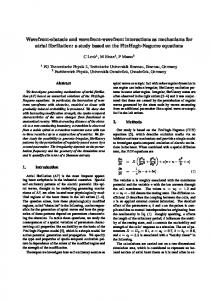
The adaptive-optics wish list generally includes the following major items: high adaptation speed, high spatial resolution, a large dynamic range of wave-front aberration correction, and a small, low-cost adaptive system. The actual requirements may vary, but the following adaptive-system parameters are likely to satisfy most adaptive-optics applications: a submillisecond time response, hundreds of control channels, wave-front shaping amplitude of several micrometers, a system the size of a shoebox, and a cost the same as a compact car. In this Letter we report on an adaptive system for dynamic phase distortion compensation that closely approaches the desired adaptive-optics goals mentioned above. The adaptive system shown in Fig. 1 is composed of two subsystems: a 132-channel microscale (m-mirror and VLSI controller) adaptive system 共mAOS兲 and a two-axis wave-front tilt-control system (TCS). A linearly polarized input beam (3-mm diameter) from a laser diode 共l 苷 690 nm兲 was ref lected from a polarizing beam splitter (PBS) and directed to a microelectromechanical system mirror (micromirror). After ref lection from the micromirror and a double pass through a l兾4 plate (WP), the input wave polarization was changed to orthogonal and passed through the beam splitter without energy loss. To introduce small-scale dynamic phase distortions we expanded the beam size to 12-mm diameter by use of lens system L1 and L2 . The expanded beam was ref lected from the tip –tilt mirror, M1 , and passed through a turbulent region. We used two soldering irons and a metal grid with a cell size of 1 mm placed 40 mm below the laser beam for generation of a turbulent airf low. A small fan was used to increase the air convection speed in the area of the laser beam. The distorted beam was divided by ⬃50% by use of beam splitter BS1 and sent (after it passed lenses L3 and L4 ) to both the TCS and mAOS photodetectors. Wave-front tilts were compensated for by use of a beam-control system based on a beam-steering mirror (Physik Instrumente) and a position-sensitive detector (PSD) from Pacific Silicon Sensor. The focal plane of lens L1 was imaged by the microscope objective (MO) 0146-9592/02/090751-03$15.00/0
onto the surface of the PSD (a duolateral photodiode with a 10 mm 3 10 mm active area), thus providing measurements of the focused beam’s x and y centroid coordinates. The corresponding x- and y-position signals from the PSD were used as feedback signals to compensate for wave-front tilts and stabilize the laser beam focal-spot position in the center of the PSD. The TCS closed-loop bandwidth was near 300 Hz. The mAOS includes a micromechanical deformable mirror array from Boston University1 (140 actuators on a 12 3 12 grid with nearly 1.5 -mm stroke for a single actuator) and a VLSI controller2 with which a stochastic parallel gradient-descent optimization control technique is implemented.3,4 In the mAOS only 132 of the 140 channels were used. The mAOS can easily meet the shoebox as well as the compact-car criteria (if both a m-mirror and a VLSI controller are commercially available). The adaptation process in the mAOS is performed through an update of iterative-control variables based
Fig. 1.
Adaptive laser-beam-focusing system setup.
© 2002 Optical Society of America
752
OPTICS LETTERS / Vol. 27, No. 9 / May 1, 2002
on an iterative stochastic approximation technique.4,5 共n11兲 On iteration 共n 1 1兲 the control voltages uj applied to N wave-front corrector electrodes 共 j 苷 1, . . . , N兲 are dependent on the product of applied random controlvoltage perturbation values 兵duj 其 and the corresponding value dJ 共n兲 of the measured system performance 共n11兲 共n兲 共n兲 metric perturbation: uj 苷 uj 1 gduj dJ 共n兲 . The value of the gain coeff icient g was controlled with an external (to the VLSI controller) supervisory system based on the use of a PC computer to increase the system convergence rate.6,7 For the system performance metric J we used the light power inside the 50-mm pinhole (PH) placed in the lens focal plane and measured by a photomultiplier (PM). This metric J is proportional to the Strehl ratio, St, commonly used in adaptive optics. The values of performance metric J were used for on-chip computations of the control voltages 兵ui 其 共i 苷 1, . . . , 132兲. These control voltages were amplif ied by a set of high-voltage (HV) amplif iers (in the range 0 to 200 V) and applied to the micromirror-array electrodes. The parallel analog on-chip control-voltage computations and the high (near 17-kHz) micromirror-array bandwidth allowed, for what is believed to be the first time, a submillisecond wave-front correction rate: The system performed 11,000 control-voltage updates (iterations) per second. The on-chip implementation of the stochastic parallel gradient-descent control technique for adaptive wave-front aberration compensation was f irst demonstrated in Ref. 8. A slower microscale (microelectromechanical system–VLSI) adaptive system with a 6 3 6 micromirror array was recently reported in Ref. 7. The fast iteration rate achieved in the adaptive system reported here enabled us to demonstrate real-time adaptive correction of turbulence-induced wave-front phase distortions. For evaluation of the dynamic wave-front aberrationcorrection efficiency a large 共M 苷 2 3 106 兲 set of performance metric values J 共n兲 共n 苷 1, . . . , M兲 were measured at the adaptive-system iteration rate. The performance metric data were used for calculation of the probability density functions (PDFs) r共J兲 corresponding to different adaptation situations. The results are presented in Fig. 2 as normalized PDF curves. In the absence of adaptation (with both mAOS and TCS off ) the PDF [curve (1)] is wide, indicating a high level of intensity scintillations. The compensation of wave-front tilts only [with the TCS on and the mAOS off, curve (3)] resulted in an increase of the averaged intensity level 具J典 (a shift of the PDF curve maximum). Note that this compensation of just wave-front tilts had almost no effect on the intensity scintillation level. The PDFs without adaptation and with tilt-only compensation have approximately the same width (compare the corresponding curves in Fig. 2). This result can be explained by the presence of strong higher-order aberrations, resulting in the appearance of several spots in the focal intensity distribution. The TCS is not able to change the intensity distribution itself and instead moves the entire beam so that the most closely located intensity spot is placed inside the pinhole. Adaptive compensation for
high-order aberrations with the mAOS only [with the TCS off, curve (2)] resulted in a noticeable decrease of the intensity scintillation level (narrowing the PDF) compared with the PDF curves corresponding to the absence of adaptation or to the tilt-control PDF curve in Fig. 2. The high-order aberration compensation with the mAOS resulted in the formation of a single focal-plane spot, thus decreasing the intensity scintillation level. Compensation for both wave-front tilts and high-order aberrations [with both the TCS and the mAOS off, curve (4)] resulted in a further (approximately twofold) increase of the average metric value. For comparison we also measured the PDF in the system without turbulence [curve (5) in Fig. 2], which corresponds to the optimal adaptation level that can be achieved. Note that this turbulence-free PDF curve is still quite wide (approximately half as wide as the corresponding curve with turbulence present). The intensity (metric) scintillations that cause the PDF curve widening in the absence of turbulence result from wave-front phase perturbations introduced by the mAOS itself. Indeed, in the absence of both turbulence and adaptation (no applied perturbations), the probability distribution curve (not shown in Fig. 2) is almost three times narrower than curve (5). The frame-averaged focal-plane intensity distributions without correction and with adaptive compensation (with both the TCS and the mAOS on) are also shown in Fig. 2 as insets. For frameaveraging we used 50 intensity distributions taken in intervals of 1 s. The pinhole position is shown by the dotted circles, which correspond to a pinhole diameter of 50 mm. Analysis of the experimental data shows that simultaneous correction of both
Fig. 2. PDFs, r, of metric values J (laser beam power inside the pinhole) and frame-averaged focal-plane intensity distributions (insets a and b) for [curves (1) – (4)] wave-front phase distortion correction in the presence of generated turbulence and [curve (5)] without turbulence. Curve (1), TCS and mAOS system off; curve (2), TCS off and mAOS on; curve (3), TCS on and mAOS off; curve (4) TCS and mAOS on; curve (5) TCS and mAOS on (no turbulence). The insets show the averaged focal-plane intensity distributions a, without and b, with wave-front distortion compensation. In b, both the TCS and the mAOS are on.
May 1, 2002 / Vol. 27, No. 9 / OPTICS LETTERS
wave-front tilts and higher-order aberrations allowed nearly 92% of the maximum possible average metric value 具J典 corresponding to undistorted conditions, to be achieved. The normalized standard deviation of the beam-quality metric sJ was decreased from 0.41 for the uncorrected case to 0.13 when the TCS and mAOS were used simultaneously. In conclusion, we have demonstrated real-time turbulence-induced wave-front phase distortion correction with a 134-control-channel adaptive-optics system consisting of a VLSI controller, a micromechanical mirror array, and a beam-steering system. Parallel analog control-voltage computation and the high bandwidth of the micromirror allowed an iteration rate of 11 kHz. The adaptive-optics system that was presented can be used for a variety of applications, for example, free-space laser communication and astronomical imaging. This work was performed at the U.S. Army Research Laboratory’s Intelligent Optics Lab. The authors are grateful to M. H. Cohen and G. Cauwenberghs for their cooperation regarding the VLSI system development and T. G. Bifano for providing the micromechanical mirror array. The research was supported in part through Cooperative Agreement DAAD17-99-2-0070 between the U.S. Army Research Laboratory and the Boston University Photonics
753
Center. T. Weyrauch thanks the National Research Council for a Research Associateship Award at the U.S. Army Research Laboratory. M. A. Vorontsov’s e-mail address is
[email protected]. References 1. T. G. Bifano, J. Perreault, R. Krishnamoorthy Mali, and M. N. Horenstein, IEEE J. Sel. Top. Quantum Electron. 5, 83 (1999). 2. R. T. Edwards, M. Cohen, G. Cauwenberghs, M. A. Vorontsov, and G. W. Carhart, in Learning on Silicon, G. Cauwenberghs and M. A. Bayoumi, eds. (Kluwer Academic, Dordrecht, The Netherlands, 1999), pp. 359– 382. 3. M. A. Vorontsov, G. W. Carhart, and J. C. Ricklin, Opt. Lett. 22, 907 (1997). 4. M. A. Vorontsov and V. P. Sivokon, J. Opt. Soc. Am. A 15, 2745 (1998). 5. J. C. Spall, in Proceedings of the American Control Conference (Institute of Electrical and Electronics Engineers, Piscataway, N.J., 1987), pp. 1161 – 1167. 6. T. Weyrauch, M. A. Vorontsov, T. G. Bifano, and M. K. Giles, Proc. SPIE 412, 178 (2000). 7. T. Weyrauch, M. A. Vorontsov, T. G. Bifano, J. A. Hammer, M. Cohen, and G. Cauwenberghs, Appl. Opt. 40, 4243 (2001). 8. M. A. Vorontsov, G. W. Carhart, M. Cohen, and G. Cauwenberghs, J. Opt. Soc. Am. A 17, 1440 (2000).