F. F. Grinstein and C. R. DeVore. Laboratory for Computational Physics and Fluid Dynamics, Naval Research Laboratory,. Washington, DC 20375-5344.
Dynamics of coherent structures and transition to turbulence in free square jets F. F. Grinstein and C. R. DeVore Laboratory for Computational Physics and Fluid Dynamics, Naval Research Laboratory, Washington, DC 20375-5344
~Received 13 October 1992; accepted 17 January 1996! We report results of time-dependent numerical simulation of spatially developing free square jets initialized with a thin square vortex-sheet with slightly rounded corner-regions. The studies focus on the near field of jets with Mach number 0.3–0.6 and moderately high Reynolds numbers. A monotonically-integrated large-eddy-simulation approach is used, based on the solution of the unfiltered inviscid equations and appropriate inflow/outflow open boundary conditions. The simulations show that the initial development of the square jet is characterized by the dynamics of vortex rings and braid vortices. Farther downstream, strong vortex interactions lead to the breakdown of the vortices, and to a more disorganized flow regime characterized by smaller scale elongated vortices and spectral content consistent with that of the Kolmogorov ~K41! inertial subrange. Entrainment rates significantly larger than those for round jets are directly related to the enhanced fluid and momentum transport between jet and surroundings determined by the vortex dynamics underlying the axis-rotation of the jet cross-section. The first axis-rotation of the jet cross-section can be directly correlated with self-induced vortex-ring deformation. However, subsequent jet axis-rotations are the result of strong interactions between ring and braid vortices, rather than being correlated with successive self-induced vortex-ring deformations, as previously conjectured based on laboratory observations. The interaction between braid and ring vortices has the effect of inhibiting the periodic self-induced axis-rotations observed in the case of isolated square vortex rings. © 1996 American Institute of Physics. @S1070-6631~96!00705-1#
I. INTRODUCTION
In recent years, there have been many efforts devoted to investigating the properties of non-circular jets1,2 motivated by their enhanced characteristic entrainment properties relative to those of comparable circular jets. The enhanced entrainment obtained with non-circular nozzles is believed to be mainly the result of self-induced vortex-ring deformations. The basic features of these deformations can be explained based on the azimuthal variation of the self-induced velocity in a thin, incompressible, inviscid vortex tube ~e.g., Ref. 3!, u;C b log~ s 21 ! ,
~1!
where C is the local curvature of the tube, s is its local cross-section, and b is the binormal to the plane containing the tube. Equation ~1! predicts a constant self-induced velocity for a thin circular vortex-ring of uniform cross-section, which in the absence of azimuthal perturbations will thus remain undistorted. Rectangular jets are of great importance in the aerospace community due to the use of vectored thrust on aircraft, and the increased mixing of the jet plume with the surroundings which decreases jet detection. The study of square jets, in particular, allows to isolate the features which are independent of aspect ratio and directly related to the rapid shearlayer curvature changes at the corners. Laboratory studies of square jets4–7 have reported 45°-axis-rotation of the jet cross-section in the near field. The near-jet flow visualizations suggest self-deformation of the corner regions of the vortex rings and considerable vortex stretching in the regions Phys. Fluids 8 (5), May 1996
aligned with the corners,5 where significant streamwise vorticity is found.6 Multiple or no occurrences of axis-rotation of the jet cross-section can be observed in square jets, depending on the initial conditions.7 The underlying fluiddynamical mechanisms leading to these observations are far from being understood, and detailed studies of the dynamics and topology of the large-scale coherent structures governing the entrainment and mixing in these jets are needed. This knowledge is crucial to determine mechanisms by which efficient active and/or passive control of the jet development in the practical applications can be achieved. In this paper we present results of such an investigation. Preliminary versions of this work have been reported previously.8 In what follows, we first address the numerical issues involved in the simulation of free jets, and discuss the jet numerical model. Next, we describe the use of the timedependent database from the simulations to investigate the large-scale vorticity dynamics of the jet. Flow visualizations based on instantaneous vorticity data are used to capture the unsteady dynamics of vortex rings and hairpin braid vortices underlying the axis-rotation process, its sensitivity to changes in jet initial conditions, and its impact on the nearjet entrainment. Finally, the major conclusions of this work are summarized. II. NUMERICAL MODEL
Compared to laboratory experiments, the structure of the instantaneous flow fields obtained through spatially evolving computer simulations is free from experimental problems such as the effects of probe interference and the highly restrictive Taylor’s hypothesis. The computations also have the
1070-6631/96/8(5)/1237/15/$10.00
© 1996 American Institute of Physics
1237
advantage of being free from problems with hot wire measurements such as high turbulence levels and flow reversal— problems that hinder measurements in the outer regions of free jet flows, while also allowing a more precise control of the effect of boundary conditions on the flow investigated. On the other hand, the kind of flow analysis that is possible based on numerical simulations is limited in practice by the computational modeling and resources available. It is prohibitively expensive with the current generation of computers and algorithms to numerically solve the unsteady Navier–Stokes equations for practical Reynolds numbers, resolving the three-dimensional dynamical features of both boundary layers at the nozzle and the free shear flow downstream. In fact, resolution requirements are considerable, even if only the fully resolved fine details of the flow structure in the neighborhood of the sharp corners of the nozzle were to be simulated. Thus, partial modeling of the physical processes in the jet becomes unavoidable. For the sake of computational efficiency, we concentrate on the study of a free jet flow initialized with a thin square vortex sheet with slightly rounded-off corner regions and uniform initial thickness. This closely models the practical problem of a laminar jet emerging from a sharp-edged orifice nozzle, where the initial shear layers have virtually zero uniform momentum thickness and the sharpness of the jet corners is smoothed out immediately downstream of the nozzle due to diffusion effects. For such orifice jets, the role of boundary layers is minimal and effectively reduced to contributing to the definition of the very thin initial vorticity thickness. Our work focuses on the large-scale free shearflow dynamics downstream of the orifice. Issues that need to be addressed in numerical simulations of jets as approached here, relate to the appropriate modeling of ~1! the unresolved ~subgrid! flow features for the large Reynolds-number regimes and ~2! the required open boundary conditions for free shear flows developing in both space and time.9 Subgrid models are needed in order to ensure the accurate computation of the three-dimensional timedependent details of the largest scales of motion responsible for the primary transport and entrainment. In the conventional large-eddy simulation ~LES! approaches10 subgrid models are explicitly introduced for closure in the filtered Navier Stokes equations, which are the ones solved numerically. A promising LES approach for transitional free jet regimes—where the vorticity dynamics is virtually inviscid —is based on the unfiltered Euler equations and involves the use of high-resolution monotone CFD algorithms such as Flux-Corrected Transport ~FCT! or the Piecewise Parabolic Method ~PPM!. For the latter schemes, ~minimal! subgrid models—provided by intrinsic non-linear high-frequency filters built into the algorithms—are coupled naturally to the resolved scales in the computed flow. Physical and numerical considerations underlying this monotonically-integrated LES ~MILES! approach used here have been discussed elsewhere.11 Properties of the FCT effective numerical viscosity relevant to the simulation of the large-scale features of free shear flows have been reported,12 and convergence studies of MILES schemes in turbulence decay investigations using PPM models indicate that the approach is capable of 1238
Phys. Fluids, Vol. 8, No. 5, May 1996
capturing the dominant inertial subrange of the energy spectrum.13 The three-dimensional jet model is based on the solution of the inviscid, time-dependent, conservation equations for mass, energy, and momentum, using the equation of state for an ideal gas.14 The equations solved are for a fully compressible flow and thus resolve the propagation of acoustic waves. Depending on the flow regime investigated, the conservation equations for chemical-species’ concentrations are also included in the model, and species- and temperature-dependent diffusive transport and finite-rate chemistry can be optionally coupled to convection in the model using timestep-splitting. These options are not included in the present non-reactive studies, but have been previously used to investigate effects of exothermicity on the development of reactive mixing layers14 and square jets.15 At the convection stage, the numerical solution of the equations is based on the use of explicit, fourth-order, finitedifference FCT algorithms on structured grids.16 Integrations are performed using a 2D FCT module17,18 for the crossstream directions and a 1D FCT module19 for the streamwise direction, which are coupled using timestep-splitting techniques. The finite-difference model is second-order in time, through use of a two-step predictor-corrector scheme. FCT ensures that all conserved quantities remain monotonic and positive ~where appropriate! during convective transport. First, it modifies the linear properties of a high-order algorithm by adding diffusion during convection to prevent dispersive ripples from arising. The added diffusion is then removed in an antidiffusion phase of the integration cycle. Hence, these calculations maintain the high order of accuracy without resorting to artificial viscosity to stabilize the algorithm. Dealing with open boundaries in the computer simulation of unsteady subsonic shear flows presents challenging problems. In studying spatially developing flows, one must face the fact that only a portion of the flow can be investigated, as in the laboratory experiments where the finite dimension of the facilities is unavoidable. We must ensure that the presence of artificial boundaries does not pollute the solution in a significant way. One difficulty is related to the basic solution of the physical flow equations, and involves choosing suitable nonlocal open boundary conditions which will adequately bound the computational domain while providing information from the virtual flow events outside— e.g., emulating the ~generally not reported! downstream conditions in the laboratory jets. A second difficulty is related to the discretized computational problem, for which additional numerical boundary conditions consistent with the unsteady flow equations and the prescribed physical conditions at the boundaries are required for closure.9 In the present simulations, inflow/outflow conditions are imposed at the open boundaries in the streamwise direction, free-slip conditions are enforced at the wall surrounding the jet orifice, and stagnant flow conditions are imposed at the cross-stream boundaries. Inflow boundary conditions modelling the initial ~jet exit! conditions for the orifice-jet investigated here specify the guard-cell values for the mass density and velocities: F. F. Grinstein and C. R. DeVore
TABLE I. Cartesian computational grids used. NX3NY 3NZ
Grid
2
1203(87) 1503(110) 2 2403(174) 2 1803(87) 2
C I F B
TABLE II. Initial and computational conditions of numerical jet simulations. Cell size 2Dx 1.5Dx Dx 2Dx
r G 5 r inflow ,
~2a!
u G 5u inflow5U 0 @ 11F~ t!# ,
~2b!
v G 5w G 50,
~2c!
where U o is the free-stream jet velocity, and ~2b! allows the jet to be forced axially by superimposing on U o an axial, time-dependent sinusoidal perturbation parametrized in the form F(t)5A f sin(2 p f t). The inflow guard-cell pressures are obtained using a characteristic-analysis approach20 as solutions of a one-sided finite-difference expression based on the one-dimensional, unsteady, inviscid pressure equation,9
S
D
]P ]P ]u ] F~ t ! 1 ~ u2a ! 2ra , 5ra ]t ]x ]x ]t
~3!
where P is the static pressure and a is the local sound speed. A non-reflecting one-dimensional boundary condition20 on the pressure is specified at the outflow boundary,
]P ]u 2 r a 50, ]x ]x
~4!
where the additional numerical conditions required for closure of the discretized equations are introduced by requiring that the mass and momentum densities be advected with the local streamwise velocity. Using boundary conditions for which the dependence on pressure involves only derivatives, as in Eqs. ~3! and ~4!, potentially allows the secular global drifting of the pressure of the system. Relaxation of the outflow pressure to ambient pressure can be used to avoid this problem ~e.g., Refs. 12 and 20!, but was not implemented in the present work, where pressure drifting was found to be negligible for the duration of the simulations. For selected cases, simulations were repeated on computational domains having a streamwise extent 50% longer to assess the sensitivity of the jet flow to changes on the downstream open boundary conditions. For these cases, flow features such as reported in this paper were found to be virtually the same. The Cartesian computational grids used in the computational studies reported in this paper are described in Table I, where Dx denotes the characteristic mesh spacing in the finest grid (F). The grids are evenly spaced in the shear flow region of interest. Geometrical stretching in the cross-stream direction outside of the latter region is used to implement the open boundary conditions there. The grids are held fixed in time, and typically use between 1203(87) 2 and 2403(174) 2 computational cells. The computational domain has a streamwise (x) extent ;5D e , and extends up to 63D e relative to the jet axis in the transverse (y, z) directions, where D e is the jet equivalent diameter, defined here as the diameter of a circular jet having the same crossPhys. Fluids, Vol. 8, No. 5, May 1996
Jet
Re
St D e
rc60 rc36 rc40 rc73 rc53 rc72 rc74
.1.2310 .7.83104 .2.23105 .8.53104 .8.53104 .1.23105 .1.23105 5
St u s
~*! ~*! 0.55 0.0073 0.55 0.0073 0.49 0.0098 0.43 0.0086 0.49 0.0065 0.49 0.0065 ~*! transient jet
De /us
M
Grid
75 75 75 50 50 75 75
0.3 0.6 0.6 0.3 0.3 0.3 0.6
I C F I I I I
sectional area, i.e., D e 52D p 21/2 , where D is the length of the sides of the square jet. Most of the simulations were performed on grid I, with Courant number c50.5. Grid B was used to assess the dependence of the jet solutions on the downstream boundary conditions. Selected runs were repeated with c50.25 and/or performed on the finer and coarser grids F and C, to establish confidence on the spatial and temporal accuracies in the simulations. III. SQUARE JET SIMULATIONS
The square jet runs investigated here are summarized in Table II. The gas jet emerges from a square orifice-nozzle into a quiescent background with Mach number M 50.320.6. The jet and background are composed of air at the same uniform initial temperature and pressure. Effects due to differences in mass density between jet and surroundings have been reported elsewhere.15 For the jets studied here with MILES, effective Reynolds number based on De jet velocity U o , and upper bounds to the effective numerical viscosity,12 are estimated to be Re D e .78,0002220,000. To facilitate the analysis of the results, the jet is forced axially by superimposing on the jet velocity a sinusoidal ~axial! perturbation with rms level 2.5%, and frequency St D e 5 f D e /U o 50.4320.55, a range consistent with the observed jet preferred frequencies in the laboratory experiments.7 As a useful reference case, a transient jet simulation (rc60) was also performed to investigate the evolution of an isolated vortex ring under similar computational and initial conditions. In the case of the transient ~as opposed to continuous! jet emerging into a stagnant background, the jet shear layer exists only for a time long enough to puff a single vortex-ring, and we investigate the development in space and time of the ring as it convects away from the nozzle. By design, vortex rings in transient jets are affected by selfinduced motions and azimuthal ring-instabilities as they are convected downstream, but are isolated from the vorticity dynamics events otherwise present upstream and downstream of the ring in continuous jets. Experimental studies of suddenly-started rectangular vortex rings ~e.g., in Ref. 21!, are examples of laboratory realizations of transient jet flows. Results of simulations of low aspect-ratio (AR52–4! rectangular transient jets have been reported separately.22 The features of the streamwise velocity at the jet exit are shown in Fig. 1. The ratio of equivalent diameter to initial momentum thickness on the sides ( u s ) was in the range F. F. Grinstein and C. R. DeVore
1239
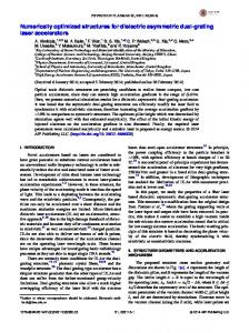
FIG. 1. Jet initial conditions. ~a! Isocontours of the streamwise velocity at ¯50.2U 0 . ~b! Comparison of streamwise the jet exit; contour interval Du velocity profiles at the exit of simulated and experimental jets.
D e / u s 550275. The contours of the streamwise velocity u at the inflow in Fig. 1~a! depict the virtually uniform thickness of the vortex sheet with rounded-off corner regions used to initialize the simulations, where the initial vertex-to-side vorticity- and momentum-thickness ratios of the profiles were ;1 and ;1.05, respectively. These ratios as well as the actual thicknesses were the same and fixed for all cases considered. Velocity profiles at the jet exit are compared in Fig. 1~b! with time-averaged data from a typical experimental orifice jet (OU1) from Ref. 7 . The profiles along radii normal to the sides (s-direction! and along the diagonal (d-direction! are plotted in terms of a transverse coordinate with an origin at R e 5D e /2 and scaled with the momentum thickness. The simple top-hat velocity profiles used to initialize the square vortex sheet for the simulated jets do not include modelling of the overshoots and contraction effects of the experimental exit profiles of orifice jets @apparent in Fig. 1~b!#. The importance of the vena contracta effects is restricted to the early stages of jet development near the orifice.7 Moreover, boundary layer effects due to small induced transverse flows near the walls surrounding the orifice are not expected to be significant and were also not accounted for. A. The spatially developing vortex ring
The dynamics of an isolated vortex ring generated with transient initial conditions (rc60) at the jet exit are shown in 1240
Phys. Fluids, Vol. 8, No. 5, May 1996
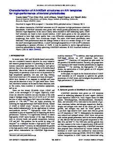
FIG. 2. Vortex ring self-deformation for the transient square jet. Isosurfaces of the vorticity magnitude for V/V peak50.4. The flow is from bottom to top in each frame, the time evolves from the bottom to the top row and from the frame on the left to that on the right in each row, and the time-interval between frames is 1.2t .
Fig. 2. This particular simulation was carried out as rc72, except for being initialized at t50 with stagnant flow throughout the computational domain, and with jet-exit velocity set to be non-zero only during a finite initial time interval. This condition was implemented by replacing Eq. ~2b! ~and performing appropriate changes in Eq. 3! by u G 5u inflow5U 0 3G ~ t ! ,
~2b8!
where G(t) was chosen to be unity during the time interval 0 & t & t , and zero otherwise. The characteristic ‘‘impulse’’ duration t was chosen as t 5D e /U o , and smooth temporal transition of the jet-exit velocity between zero and U o at the edges of the transient pulse was imposed within times of the order of 0.05t . By construction, t corresponds to a Strouhal number St5(1/t )D e /U o ;2St p , where St p;0.5 is a typical preferred value of square7 laboratory jets, and is thus designed to hinder the roll-up of more than one vortex ring. Based on tangential-velocity and azimuthal-vorticity data at the centers of the flat sides of the initial vortex rings, their characteristic circulation and core radius were G'0.7U o D e and s ;0.25R, respectively, where R5 p 1/2 R e /2 is the halflength of the side of the square nozzle. In Fig. 2, the evolution of the isolated square vortex ring is visualized in terms of instantaneous isosurfaces of the vorticity magnitude V5( v 2x 1 v 2y 1 v 2z ) 1/2 , for V50.4V peak , where V peak is the initial peak value. The flow is from bottom to top in each frame, the time evolves from the bottom to the top row and from the frame on the left to that on the F. F. Grinstein and C. R. DeVore
FIG. 4. Near jet half-width B s1/2 for simulated and experimental square orifice jets.
FIG. 3. Trajectories of vortex core centers. ~a! Cross-stream; ~b! streamwise.
right in each row. Due to self-induced motions in the neighborhood of the corners, the corner portions of a virtually flat and square vortex ring move ahead faster. In turn, as the ring portions that are left behind ~e.g., at centers of initial flat sides! eventually develop higher curvature, they move ahead by the same mechanism, and the vortex ring becomes again approximately flat, with axes rotated 45° relative to those in the previous planar configuration. After several axis rotations, the ring becomes quite distorted. These contortions are attributed to the growth of azimuthal ring instabilities,23 with the dominating eight-fold-symmetric mode observed at the late stages of ring development, reflecting the imprint of the 45° axis-rotation process determined by the ~square-shaped! jet initial conditions. Figure 3 illustrates the evolution of this axis-rotation process as the vortex ring is convected downstream, based on unsteady data obtained at equally spaced times ~timeinterval 0.2t ). The traces in Fig. 3 represent the paths of the locations of the vortex-core centers in planes passing through the jet axis: ~1! normal to the sides ~‘‘s’’! and ~2! along the diagonals ~‘‘d’’! of the initial jet cross-section. The trajectories of the cross-stream ~Fig. 3a! and streamwise ~Fig. 3b! locations are separately shown. Based on tests examining the dependence on grid resolution of the trajectories in Fig. 3,22 the accuracy of the trajectory points in Fig. 3 was estimated to be better than 5%. During the roll-up period (t & t ), the cross-stream paths clearly show a fast spread of the jet shear layer at the centers of the flat sides, contrasting with a nearly constant spread along the diagonals ~Fig. 3a!. For later times, the paths rePhys. Fluids, Vol. 8, No. 5, May 1996
flect the 45°-axis-rotations of the ring square section, with the ring undergoing a planar phase approximately at the locations where opposite extrema of the two cross-stream trajectories are aligned vertically ~Fig. 3a!, also roughly coinciding with the crossover of the streamwise paths ~Fig. 3b!. The behavior of the streamwise trajectories between crossovers reflects the basic features of self-induced vortex-ring deformation: the higher curvature ‘‘corner’’ portions of the ring being first convected downstream faster, and then slowing down as the next crossover point is approached, when old ‘‘corners’’ become centers of ‘‘flat’’ sides in the new axis-rotated configuration. The mean convection velocity of the isolated square rings was U conv;0.3U o , with an average axis-rotation period of ;2.5t , corresponding to a ~Strouhal! frequency St D e ;0.4. B. The spatially developing jet
Extensive comparison of global properties of simulated jets and experimental laboratory jets, based on time-averaged velocity and turbulence intensity data, were performed to validate the numerical simulations of spatially developing, free square jets ~e.g., Ref. 7!. Mean global jet properties were obtained by temporally averaging the appropriate flow quantities over eight forcing periods after the initial transients are convected out of the computational domain, which was found to be adequate in the initial portions of the near jet, where the flow features are largely locked to the forcing period. A representative sample of these comparisons is shown below for completeness. Figure 4 compares the initial streamwise evolution of the ~continuous! square jet mean half-width in the s-direction, B s1/2 , of unforced experimental, low-subsonic, sharp-edged, orifice jets ~Table III! with those of the present ~weakly! TABLE III. Initial conditions of laboratory jets in Fig. 4: QUI ~Ref. 23!, OU1 ~Ref. 7!. Jet
Re
M
De /us
u 8o /U o
QUI OU1
;2.03105 4.23104
,0.2 ,0.1
182 164
0.005 0.003
F. F. Grinstein and C. R. DeVore
1241
FIG. 5. Instantaneous volume visualizations of the vorticity magnitude for the jet rc40. The flow direction is from bottom to top in each frame, the frames were chosen regularly with a time spacing of 0.6f 21 , with the temporal sequence progressing from the top-left towards the bottom-right. The color shading in the frames ranges from semi-transparent blue to opaque red, corresponding to the range 0.05V peak –0.60V peak ~the mapping relating vorticity magnitude with hue and opacity is linear for V.0.20V peak).
excited simulated jets. The laboratory jet cases chosen for reference (QUI 24 and OU1 7!, were characterized by nearly laminar initial conditions ~very low turbulence level at the jet exit, as specified by the centerline streamwise-velocity rms fluctuations u o8 ). The computed half-widths shown in Fig. 4 are averages of those obtained in the transverse (y,z) directions normal to the flat sides of the initial jet cross-section. In each of the latter directions, the half-width point of the jet at the given streamwise location is that at which the mean axial velocity drops to half of its centerline value. Vena contracta effects are responsible for the differences between simulations and experiments immediately downstream of the jet exit and for the trend to lower B s1/2 for x→0 for the experimental jets. Otherwise, the agreement on the initial growth rate is very good. The dependence of B s1/2 ~and B d1/2) on initial conditions such as the ratio D e / u s and turbulence level has been addressed in previous work.7 Figures 5–7 exemplify the developed square jet dynam1242
Phys. Fluids, Vol. 8, No. 5, May 1996
ics based on the databases for the high-Re run rc40 and the low-Re run rc36. To minimize the significance of flow transients, the snapshots in the figures correspond to times t.3t conv , where t conv is the time for streamwise convection with velocity U o across the computational domain. The jet visualizations in Figs. 5 and 6 involve instantaneous volume ~ray-tracing! renderings of V. The figures depict the square vortex sheet rolling up into vortex rings near the inflow, self-induced distortion of the nominally-square vortex rings, formation of hairpin ~braid! vortices upstream of the distorted rings, strong coupling of these vortices into ringhairpin bundles, and merging of these vortex bundles. Vortex interactions and azimuthal instabilities lead to more contorted vortices; vortex stretching, kinking, and reconnection lead to their breakdown, and to a more disorganized flow regime farther downstream, characterized by elongated vortices resembling those typical of fully developed turbulent flows.13,25 F. F. Grinstein and C. R. DeVore
FIG. 6. Instantaneous volume visualizations of the vorticity magnitude for jets rc40 ~top! and rc36 ~below! on grid C, based on snapshots taken at correspondingly identical times. Data from rc40 has been linearly interpolated into grid C using a three-dimensional eight-point stencil. Choices of color qualifiers are same as for Fig. 5. Flow direction is from bottom to top in each frame, and the temporal sequence progresses from left to right.
Runs rc40 and rc36 were performed on grids F and C, respectively, with otherwise identical conditions, so that in addition to providing an assessment on the dependence of the jet dynamics on finite Re, their comparison can also be utilized to address issues of spatial resolution of the simulations. Figure 6 compares typical visualizations on grid C based on the filtered velocity data from rc40, with corresponding ones ~at the same times! for rc36. Figure 6 shows quite good agreement on the large-scale dynamics of ring and hairpin vortices near the jet exit, indicating their somewhat faster breakdown farther downstream for larger Re. The use of spectral analysis below compares the small-scale jet behavior captured by the simulations. 1. Braid vortices and axis rotation
The initial self-deformation of the vortex ring in the continuous jet depicted in Fig. 5 is similar to that discussed above for the isolated ring. As this deformation progresses, however, it induces distortions of the square vortex loops in Phys. Fluids, Vol. 8, No. 5, May 1996
the initial jet shear-layer upstream. This is illustrated in the layout of Fig. 7 in terms of instantaneous isosurfaces of V and selected vortex lines, based on the data from rc40. Vortex-loop distortions occur in opposite directions as those in the ring: the centers of the flat sides of the loops are displaced downstream towards the nearest portions of the rings, while the loop corners tend to stay behind. Concentration and stretching of these deformed vortex loops ~as a new self-distorting ring rolls up behind! lead to the formation of braid vortices, involving ~1! hairpin-like vortices aligned with the corner regions upstream, and ~2! legs of neighboring hairpins connected by wrapping the vortex ring downstream ~from the inner side of the jet!. As the new vortex ring rolls up upstream and undergoes self-deformation, its corners move ahead and towards the jet axis, and away from the hairpin heads. In turn, as the jet spreads, the higher-curvature upstream tips of the hairpins move ahead and away from the jet axis, also due to self-induction. Figure 5 also indicates the presence of pairs of ~counter-rotating! longitudinal rib vortiF. F. Grinstein and C. R. DeVore
1243
FIG. 7. Instantaneous visualization of jet rc40 in terms of isosurfaces of constant vorticity magnitude (V/V peak50.5!, and selected vortex lines. The times correspond to those of the bottom-left ~a! and bottom-right ~b! frames in Fig. 5. Vortex lines through the vortex-ring cores have been also traced for reference in ~b!.
FIG. 8. Topological interaction models flows. ~a! Rings and braid vortices in vortices in the elliptical jet ~from Ref. vortices in the mixing layer ~from Ref.
ces developing in the high-strain region between hairpin tips and ring corners immediately upstream. Two kinds of hairpin vortices are apparent in the frame at the bottom right of Fig. 5: the ones discussed above, developing between rings that will eventually undergo a merging interaction ~such as depicted in the layout of this figure!, and the ones with larger longitudinal dimensions, which have developed upstream of the pairing rings, and undergo additional stretching due to advection by the core fluid as their legs are pulled towards the jet axis by the downstream-merging’s induction. Figure 7b shows the coupling of instantaneous vortex lines passing through the cores of two neighboring vortex rings which are strongly linked by continuous vortex lines passing through the cores of the braid vortices, suggesting the topological coherent-structure interaction model indicated schematically in Fig. 8a. The interaction between braid vortices and vortex rings in the square jet is reminiscent of that in elliptical jets shown in Fig. 8b ~Fig. 9b of Ref. 25! and of the interaction between counterrotating ribs and spanwise rollers in the mixing layer indicated in Fig. 8c ~Fig. 11c of Ref. 26!. Axis rotation of the jet cross-section has been conjectured to be directly correlated with successive axis-rotation
of nominally-square vortex rings.5 However, after the initial vortex ring self-deformation the vortex-ring dynamics is different from that of the isolated ring discussed above. This is due to the strong vortex interactions, particularly those between vortex rings and braid vortices, which were not previously recognized based on the experimental data ~the existence of braid vortices in the square jet was first demonstrated by the numerical simulations!. The braid vortices induce flattening of the vortex-ring portions left behind – in contrast with high curvature developed at the centers of ‘‘old’’ flat sides in the isolated-ring case. The faster-advancing corners of the ring immediately upstream can also contribute to the latter induced flattening ~depending on the relative separation between successive vortex rings as determined by the jet initial conditions!. As a consequence of this induced flattening, the subsequent ~isolated-ring! phase of self-deformation by which the ring approximately recovers its flatness with axis rotated 45° ~Fig. 5! does not occur, and vortex-ring axis-rotations are inhibited in the continuous jet. Figure 9 shows the vorticity dynamics underlying the first axis-rotation of the jet cross-section in the square jet ~based on data from rc73). Observing a self-deforming square vortex ring from upstream in terms of isosurfaces of
1244
Phys. Fluids, Vol. 8, No. 5, May 1996
for coherent structures in free shear the square jet; ~b! rings and braid 25!; ~c! spanwise rollers and braid 26!.
F. F. Grinstein and C. R. DeVore
FIG. 9. Instantaneous visualization of rc73 in terms of isosurfaces of constant vorticity magnitude (V/V peak50.25! depicting the 45° –axis-rotation of the jet cross section. ~a! side view; ~b! view from the nozzle; ~c!–~e! contours in planes at fixed streamwise locations.
V ~Fig. 9b! suggests the axis-rotation of the ring with respect to the initial square section. A first axis-rotation of the jet cross-section is depicted by the vorticity distributions in planes at fixed streamwise locations, shown in Figs. 9c–9e. However, it is clear that more than just axis-rotation of the rings is involved in this process, since the rings become quite distorted from their original shape and are far from being planar, while the shape of the jet cross-section is also significantly affected by the presence of the hairpin vortices. The streamwise locations at which the axis-rotation of the jet cross-section occurs can be determined in terms of the crossover locations of the time-averaged half-widths in the s- and d-directions. The latter analysis was reported in Ref. 7, where it was shown that depending on the particular jet initial conditions ~e.g., turbulence level, momentum thickness distributions, ratio D e / u s , and Re) several or no axisrotations can occur in the first few diameters of jet development. The first crossover reflects faster spread of the jet mixing layer at the flat sides (s-directions! and shrinking in the d-directions ~due to the corner portions moving faster ahead and towards the jet axis!. In the absence of a new axis-rotation of the vortex ring, the faster growth in the d-direction necessary to have a second crossover ~and hence a new axis-rotation of the jet cross-section! becomes directly linked7 to the mixing-layer growth in the d-direction determined by the hairpin vortices and by the degree of induced flattening imposed on the upstream portions of the undulating vortex rings. The effects of initial conditions on characteristic timeaveraged features of the jet were addressed in Ref. 7. Figure 10 illustrates the sensitivity of the global patterns of the jet vorticity dynamics to changes in M , St D e , and D e / u s . Comparison of the two layouts on the lower-half of Fig. 10 shows that changes in Mach number within the range M 50.3–0.6 do not affect the jet dynamics in a significant way. The initial Phys. Fluids, Vol. 8, No. 5, May 1996
ring self-deformation and dynamics of mutually induced motions between neighboring vortex ring and hairpin vortices discussed above, are found to be virtually the same in all cases. The later jet development is affected by the interaction between neighbor ring-hairpin bundles ~determined by the axial-forcing frequency!, as well as by feedback motions induced by the vorticity dynamics farther downstream ~e.g, Ref. 28!. Comparison of Figs. 10a-c, associated to increasingly lower forcing frequencies St u s , respectively, shows that the merging of neighbor ring-hairpin bundles ~also depicted in Fig. 5, above! is one of the strong interaction processes that is promoted, as the separation between bundles decreases. Due to mutually induced deformations during the pairing process, at the early stages of a pairing interaction the mean radius of the ring upstream is reduced as the ring moves inward, closer to the axis, and is accelerated, while the ring downstream goes through the opposite process, resembling – in this very basic aspect – the leapfrog vortexring pairing mechanism in axisymmetric jets ~e.g., Ref. 29!. As Fig. 10a and b suggest, however, the actual merging process is much more complicated here than in the purely axisymmetric case, because of the involvement of the braid vortices and of the major role played by azimuthal instabilities, vortex stretching and reconnection leading to the breakdown of the rings. Analysis of detailed merging mechanisms are the subject of ongoing studies – beyond the scope of the present paper – and will be reported separately. 2. Transition to turbulence
In this section we use spectral analysis to make quantitative statements on the trends of the population of the smallscales in the more disorganized downstream portion of the transitional jets. The analysis is based on the velocity databases for rc36 and rc40, cases with lowest and highest Re investigated, respectively. Figure 11 shows one-dimensional FFT analysis for rc40 based on temporal fluctuations of the kinetic energy at fixed stations along the jet centerline. The timeseries for this analysis used velocity data for the developed jet taken over a time interval of eight forcing periods. The figure shows kinetic-energy spectra at a location characteristic of the disorganized jet flow downstream (x54D e ) compared with that near the jet exit. The latter spectrum shows a peak in the neighborhood of the single-frequency axial-forcing at the inflow (St Df 50.55), which appears broadened due to feedback e effects. The imprint of this fundamental mode is apparent at the downstream location, where the spectrum also shows the f trace of the first subharmonic St D /2, associated with pairing e of hairpin-ring bundles, and the population of higher frequency levels following a f 2(1.660.05) power law, suggestive of the Kolmogorov spectrum in the inertial subrange ~see below!. Spatial FFT analysis of the jet databases was performed based on instantaneous velocity data on (140) 3 and (70) 3 ~uniformly spaced! grid subvolumes for rc40 and rc36, respectively. These volumes included only the appropriate downstream portions of the jets chosen symmetrically around the jet centerline. The instantaneous velocity is deF. F. Grinstein and C. R. DeVore
1245
FIG. 10. Unsteady vorticity dynamics vs initial conditions. ~a! rc73 (St u s 50.0098, D e / u s 550, M 50.3!; ~b! rc53 (St u s 50.0086, D e / u s 550, M 50.3!; ~c! rc72 (St u s 50.0065, D e / u s 575, M 50.3!; ~d! rc74 (St u s 50.0065, D e / u s 575, M 50.6!. Other captions are as in Fig. 6.
1246
Phys. Fluids, Vol. 8, No. 5, May 1996
F. F. Grinstein and C. R. DeVore
FIG. 11. Centerline kinetic energy spectra for jet rc40 as a function of non-dimensionalized frequency St D e .
composed into its solenoidal and compressible components v5vs 1vc , with the condition ¹•vs 50 in physical space translating into the condition k•vˆs 50 in Fourier space. The latter condition is explicitly used to split the Fourier velocity transform into its corresponding components, vˆ5vˆs 1vˆc , using vˆc 5(vˆ•k)k/k 2 , and vˆs 5vˆ2vˆc . Figure 12 shows scatter plots of the solenoidal and compressible velocity spectra for rc40 based on datasets for ten successive times separated by Dt50.2f 21 . The largest wavenumber for which spectral amplitudes are plotted corresponds to a wavelength of 4Dx, where Dx is the mesh spacing of the grid. The amplitudes consistently show peaks in the neighborhood of k 1 .3.33 ~corresponding to the lengthscale D542Dx imposed by the geometry of the problem!, and of k 2 .5.38 ~corresponding to a lengthscale .26Dx, about one-half the wavelength imposed by the axial-forcing of the jet!. The scatter of the amplitudes is quite small for the larger wavenumbers (k . ; k 2 ). The greater scatter for smaller wavenumbers (k , ; k 2 ) depicts the unsteadiness of the contents of the volume analyzed ~due to large-scale structures entering and/or leaving the volume!. The spectrum for the solenoidal velocity component characterizing the vortical motions ~Fig. 12! shows an inertial range , 2(1.6560.07) for 5 , , consistent ; k ; 14 following a power law k 25/3 with the k ~inviscid! subrange of the Kolmogorov cascade theory.30 The compressible spectrum appears somewhat shallower in the latter range, following a power-law k 2(1.5260.09) . The inertial range is followed by faster decay of the amplitudes due to the FCT dissipation for wavelengths l, ; 10Dx. As exemplified by the vorticity contours at crosssectional planes in Fig. 13, the smallest characteristic ~fullwidth! cross-sectional lengthscales ( s ) of the vortex tubes in the transitional region of the jet are found to be s /Dx.425. This limiting lengthscale corresponds to a velocity perturbation wavelength l/Dx.8210, and is thus associated with the threshold wavelength-value for the dissipation range indicated by the spectral analysis. Figure 14 compares corresponding instantaneous velocity spectra for rc36 and rc40 for two typical times. As pointed out above, in connection with Fig. 6, because these runs were, respectively, performed on grids F and C, with otherwise identical conditions, the comparisons in Figs. 14 reflect on both, the sensitivity of the spectra to changes in Phys. Fluids, Vol. 8, No. 5, May 1996
FIG. 12. Scatter spectra for jet rc40 for solenoidal and compressible spectral velocity components, based on ten snapshots equally-spaced in time ~interval 0.2/f!.
Re and the spatial resolution of the simulations. For the sake of these comparisons the data for the lower resolution simulation rc36 were shifted in the figures by 13dB in wavenumber and 25dB for the amplitudes, corresponding to a Kolmogorov scaling. Figure 14 reaffirms the convergence features suggested by Fig. 6 by showing similar trends for corresponding amplitudes and self-similar behaviors on the smallest resolved scales. 3. Entrainment
Because the vorticity field is not easily extracted from experimental measurements, it is usually not possible to distinguish between the contributions from rotational and irrotational fluid in the measurements of the jet entrainment rates. Frequent approximate measures of the entrained fluid are then based on the spread of the velocity profile, that is, from the rate of increase of the streamwise mass flux, so that the resulting entrainment measurement involves fluxes of both vortical and nonvortical fluids. Examples of these entrainment measurements are the definition of entrained fluid in terms of volumetric fluxes ~e.g., Ref. 31!, and the socalled passive scalar entrainment ~e.g., Ref. 32!. Measurements of jet entrainment based on comparing ~timeaveraged! streamwise mass fluxes with their jet-exit values,7 indicate that the near-jet entrainment of subsonic square jets is not very sensitive to changes in M , and that their rate of streamwise growth – i.e., the jet entrainment rates – are significantly larger ~e.g., ;40%–50% larger! than corresponding near-jet rates for fairly typical (M 50.5! round-jet data from Ref. 33 ~also shown in the comparisons below!. When vorticity information on the flow is readily available, as given by the database from numerical simulations, one can regard a given fluid element as entrained fluid if its vortical content is above a certain specified threshold V o . 26,27 More specifically, the entrainment rate at the streamwise location x is estimated in terms of the rate of increase of the non-dimensional ratio Q(x,t)/Q o , where the flux of rotational fluid Q(x,t) is defined by Q ~ x,t ! 5
E
V.V o
r udydz, F. F. Grinstein and C. R. DeVore
~5! 1247
FIG. 13. Instantaneous vorticity contours in cross-sectional planes for a typical snapshot of jet rc40. Contours range between 0.025V peak –0.50V peak . ~a! Contours in a plane passing through jet axis ~containing s-directions!; ~b! enlarged downstream (140) 2 -subregion of the slice in ~a!; ~c! contours in a cross-stream plane at streamwise location indicated in ~a!.
and Q o is the initial reference flux at x50. The integration is carried out in the (y,z)-plane at the streamwise location x, including only the fluid elements for which the vorticity magnitude satisfies V.V o , where V 0 specifies the vorticity , threshold ~e.g., V o /V peak; 0.05!. The unconstrained mass flux Q frequently used as a measure of entrainment ~e.g., as in Ref. 7!, corresponds to evaluating the time-averaged Q for V o 50. Figure 15 illustrates the unsteady jet entrainment dynamics based on the data for jet rc73 at selected times, including phases of vortex-ring roll-up, self-induced deformation, pairing, and breakdown of the coherent structures. The streamwise variations of Q(x,t) shown are associated with thresh1248
Phys. Fluids, Vol. 8, No. 5, May 1996
olds V o specified by V o /V peak50 and V o /V peak50.05. For reference, the unconstrained ~time-averaged! round-jet data from Ref. 33 have also been plotted in the figure. Since the same normalization factor Q o is used for the square-jet curves, their differences at each time are due to the contributions of the ‘‘irrotational’’ fluid ~defined here as having vorticity content V/V peak,0.05!. The top curves, corresponding to the unconstrained mass fluxes, are quite insensitive to the detailed vorticity dynamics. The bottom curves show peaks in the neighborhood of streamwise locations, where the local instantaneous thickness of the mixing layer is enhanced by the formation or interaction of vortex rings. The F. F. Grinstein and C. R. DeVore
where fluid and momentum transport between the jet and its surroundings are considerably enhanced by the presence of the hairpin vortices aligned with the corners. A precise evaluation of the unsteady jet entrainment rates, resolving the vorticity-bearing and potentialfluctuating parts as discussed above, was used in studies of the combustion dynamics in reactive square jets to demonstrate the close correlation between local entrainment rates and instantaneous chemical reaction rates.15 IV. SUMMARY AND CONCLUSIONS
FIG. 14. Velocity spectra for jets rc36 and rc40 corresponding to the first two frames in Fig. 6.
rates of entrainment of fluid from the surroundings into the jet, dQ(x,t)/dx.0, first become significantly larger than those for a round jet in the regions of roll-up and initial self-deformation of rings (x'D e ), and then farther downstream, associated with the vortex-bundle merging region,
The focus of this work has been on investigating the dynamics and topology of large-scale vortical structures developing from thin vortex sheets having square crosssections with slightly rounded corner regions. The basic spatial and temporal features of the transitional ~initially laminar! square jets thus defined, are controlled by the dynamics—formation, development, interaction, and breakdown—of vortex rings and hairpin ~braid! vortices. The existence and important role of the braid vortices in the square jet was not recognized previously, and was first demonstrated by the numerical simulations. Hairpin vortices are formed in the high-strain regions between successive vortex rings as a result of the deformation, concentration, and stretching of braid vortex loops induced by the undulating rings. The results of the simulations support the concept that the basic mechanism for the first axis-rotation of the jet cross-section is the self-deformation of the vortex rings due
FIG. 15. Unsteady entrainment dynamics of jet rc73. Time interval between consecutive snapshots is 0.5f 21 . ~a! Volume visualization of V; ~b! jet entrainment measurements in terms of the streamwise variation of the unconstrained (V o 50! and vorticity-constrained (V o 50.05! mass flux Q, with unconstrained round-jet time-averaged data from Ref. 31 included for reference ~dashed traces!; isocontours of V in planes passing through the jet axis normal to the flat sides ~c! and through the corners ~d!. Phys. Fluids, Vol. 8, No. 5, May 1996
F. F. Grinstein and C. R. DeVore
1249
to the rapid change in azimuthal curvature at the corners of the initial square vortex sheet. However, subsequent axisrotations of the jet cross-section are not linked to successive vortex-ring axis-rotations, as previously speculated based on laboratory data. In contrast with the dynamics of isolated vortex rings—undergoing quite regular axis-rotations under the effects of self-induced motions—rings in the continuous jet do not recover their shape and flatness after the initial self-deformation. This is mainly due to strong interactions between ring and braid vortices, which inhibit axis-rotations of the rings. Hairpin vortices induce flattening of the ring portions left behind after the initial ring self-deformation, and this flattening mechanism can become the initial phase of a second axis-rotation of the jet cross-section. The sensitivity of the global patterns of jet vorticity dynamics to changes on initial conditions as specified by Mach number, axial forcing frequency, and ratio of characteristic jet length scales D e / u o , were demonstrated in terms of instantaneous visualizations of vorticity data. Compressibility effects on the jet dynamics were not found to be significant for the range of Mach numbers investigated. Although the dynamics of initial ring self-deformation and mutually induced motions between neighbor vortex ring and hairpin vortices were found to be virtually the same in all cases, the later jet development is affected by the degree of interaction between neighbor ring-hairpin bundles—dependent on the characteristic spacing between vortex bundles—which is mainly controlled by the axial-forcing frequency. Merging of vortex bundles is one of the strong interaction processes that can be promoted, as the separation between bundles becomes smaller. Farther downstream, vortex interactions and azimuthal instabilities lead to more contorted vortices, to their breakdown, and to a more disorganized flow regime characterized by smaller-scale, elongated vortex tubes. Spectral analysis used to obtain quantitative trends on the population of small-scales in this more disorganized downstream portion of the transitional jets reveals a small dynamical inertial range with scaling consistent with Kolmogorov’s k 25/3 power law. Entrainment measurements were obtained based on instantaneous evaluations of the streamwise mass flux, to examine the impact of the special features of the unsteady jet dynamics associated with having corner regions in the initial jet shear shear layer. The contribution of the vorticitybearing fluid in these measurements was assessed by calculating the streamwise vortical fluid flux, where the mass-flux evaluation is restricted to using only fluid elements with vortical content above a small specified threshold value. In the initial near-jet region investigated here, entrainment rates significantly larger than those of a round jet were shown to be directly related to vortex-ring self-deformation and the presence of hairpin vortices aligned with the corner regions. ACKNOWLEDGMENTS
This work was sponsored by the Mechanics Division of ONR, Dr. Gabriel Roy, Scientific Officer, and by NRL. The calculations were performed at the computing facilities of NAS/NASA and HPC-MP/CEWES. The authors acknowledge many helpful and stimulating discussions with E. Gut1250
Phys. Fluids, Vol. 8, No. 5, May 1996
mark, F. Hussain, J. P. Boris, and J. Dahlburg, and the invaluable assistance of U. Obeysekare with the flow visualization. 1
H.S. Husain and A.K.M.F. Hussain, ‘‘Controlled excitation of elliptic jets,’’ Phys. Fluids 26, 2763 ~1983!. 2 C.M. Ho and E. Gutmark, ‘‘Vortex induction and mass entrainment in a small-aspect ratio elliptic jet,’’ J. Fluid Mech. 179, 383 ~1987!. 3 G.K. Batchelor, An Introduction to Fluid Dynamics ~Cambridge University Press, London, 1967!, p. 510. 4 E. Gutmark, K.C. Schadow, T.P. Parr, D.M. Hanson-Parr, and K.J. Wilson, ‘‘Noncircular jets in combustion systems,’’ Exp. Fluids 7, 248 ~1989!. 5 K. Toyoda and F. Hussain, ‘‘Vortical structures of noncircular jets,’’ in Proceedings of the 4th Asian Congress of Fluid Mechanics, Hong Kong, 21–25 August, 1989, pp. A117–A127. 6 W.R. Quinn, ‘‘Streamwise evolution of a square jet cross-section,’’ AIAA J. 30, 2852 ~1992!. 7 F.F. Grinstein, E. Gutmark, and T. Parr, ‘‘Near-field dynamics of subsonic, free square jets. A computational and experimental study,’’ Phys. Fluids, 7, 1483 ~1995!. 8 F.F. Grinstein, ‘‘Coherent–structure dynamics in spatially–developing square jets,’’ Bull. Am. Phys. Soc. 36, 2699 ~1991!; AIAA Paper 92-3441 ~1992!. 9 F.F. Grinstein, ‘‘Open boundary conditions in the simulation of subsonic turbulent shear flows,’’ J. Comput. Phys. 115, 43 ~1994!. 10 W.C. Reynolds, in Whither Turbulence? Turbulence at the Crossroads, Lecture Notes in Physics, edited by John Lumley ~Springer-Verlag, New York, 1990!, Vol. 357, pp. 344–353. 11 J.P. Boris, F.F. Grinstein, E.S. Oran, and R.J. Kolbe, ‘‘New insights into large eddy simulation,’’ Fluid Dyn. Res. 10, 199 ~1992!. 12 F.F. Grinstein and R. S. Guirguis, ‘‘Effective viscosity in the simulation of spatially evolving shear flows with monotonic FCT models,’’ J. Comput. Phys. 101, 165 ~1992!. 13 D.H. Porter, A. Pouquet, and P.R. Woodward, ‘‘Kolmogorov-like spectra in decaying three-dimensional supersonic flows,’’ Phys. Fluids 6, 2133 ~1994!. 14 F.F. Grinstein and K. Kailasanath, ‘‘Chemical energy release and dynamics of transitional reactive shear flows,’’ Phys. Fluids A 4, 2207–2221 ~1992!. 15 F.F. Grinstein and K. Kailasanath, ‘‘Three-dimensional numerical simulations of unsteady reactive square jets,’’ Combust. Flame, 100, 2 ~1995!; 101, 192 ~1995!. 16 D.L. Book, J.P. Boris, and S.T. Zalesak, Flux-Corrected Transport, in Finite-Difference Techniques for Vectorized Fluid Dynamics Calculations,’’ edited by D.L. Book ~Springer-Verlag, New York, 1981!, pp. 29– 41. 17 C.R. DeVore, ‘‘Flux-corrected transport algorithms for two-dimensional compressible magnetohydrodynamics,’’ Naval Research Laboratory Memorandum Report No. 6544, Washington DC, 1989. 18 C.R. DeVore, ‘‘An improved limiter for multidimensional flux-corrected transport,’’ submitted to J. Comput. Phys. 19 J.P. Boris, J. Gardner, A. Landsberg, G. Patnaik, and E.S. Oran, ‘‘LCPFCT—A monotone algorithm for solving continuity equations,’’ Naval Research Laboratory Memorandum Report No. 6410–93–7192, 1993. 20 T.J. Poinsot and S.K. Lele, ‘‘Boundary conditions for direct simulations of compressible viscous flows,’’ J. Comput. Phys. 101, 104 ~1992!. 21 J.R. Hertzberg and C.M. Ho, ‘‘Three-dimensional vortex dynamics in a rectangular sudden expansion,’’ J. Fluid Mech. 289, 1 ~1995!. 22 F.F. Grinstein, ‘‘Self-induced vortex ring dynamics in subsonic rectangular jets,’’ Phys. Fluids 7, 2519 ~1995!. 23 S. Widnall, ‘‘The structure and dynamics of vortex filaments,’’ Annu. Rev. Fluid Mech. 7, 141 ~1975!. 24 W. R. Quinn and J. Militzer, ‘‘Experimental and numerical study of a turbulent free square jet,’’ Phys. Fluids 31, 1017 ~1988!. 25 J. Jimenez, A. Wray, P. Saffman, and R. Rogallo, ‘‘The structure of intense vorticity in isotropic turbulence,’’ J. Fluid Mech. 255, 65 ~1993!. 26 H.S. Husain and F. Hussain, ‘‘Elliptic jets. Part 3. Dynamics of preferred mode coherent structure,’’ J. Fluid Mech. 248, 315 ~1993!. 27 F.F. Grinstein, E.S. Oran, and A.K.M.F. Hussain, ‘‘A numerical study of mixing control in spatially evolving shear flows,’’ AIAA Paper 89-0977 ~1989!. 28 F.F. Grinstein, E.S. Oran, and J.P. Boris, ‘‘Pressure field, feedback, and F. F. Grinstein and C. R. DeVore
global instabilities of subsonic spatially developing mixing layers,’’ Phys. Fluids A 3, 2401 ~1991!. 29 F.F. Grinstein, F. Hussain, and E.S. Oran, ‘‘Vortex-ring dynamics in a transitional subsonic free jet. A numerical study,’’ Eur. J. Mech. B Fluids 9, 499 ~1990!. 30 A. N. Kolmogorov, ‘‘The local structure of turbulence in incompressible viscous fluids at very large Reynolds numbers,’’ Dokl. Nauk. SSSR. 30, 301 ~1941!.
Phys. Fluids, Vol. 8, No. 5, May 1996
31
A.K.M.F. Hussain and A.R. Clark, ‘‘On the coherent structure of the axisymmetric mixing layer: A flow visualization study,’’ J. Fluid Mech. 104, 263 ~1981!. 32 S.M. Masutani and C.T. Bowman, ‘‘The structure of a chemically reacting mixing layer,’’ J. Fluid Mech. 172, 93 ~1986!. 33 K.B.M.Q. Zaman, ‘‘Flow field and near and far sound field of a subsonic jet,’’ J. Sound Vibr. 106, 1 ~1986!.
F. F. Grinstein and C. R. DeVore
1251