Jun 26, 2008 ... This course was designed for engineers working on engines testing. The hope is
that after attending this course you will be better able to:.
Dynamometry and Testing of Internal Combustion Engines Seminar June 26-2008 University Science Malaysia Dr. Horizon Gitano-Briggs 3750
P=0.3 D=0.3
P=0.3 D=0.0
3500 3250 3000
P=0.3 D=1.0
2750 2500 2250 2000 0
10
20
30
40
50
60
70
80
1
OUTLINE Part 1 Basics What is a Dynamometer? - The Basics Dynamometer Designs Mechanical Details Part 2 Measurements Measurements: Cycle Averaged vs. Crank Angle Resolved Instrumentation Issues Testing: Steady State vs. Transient Controllers Dynamometer Dynamics Part 3 Drive Cycles Analysis Drive Cycles Test point Determination and Weighting Part 4 Dynamometry Case Studies USA Philippians Malaysia 2
OBJECTIVES This course was designed for engineers working on engines testing The hope is that after attending this course you will be better able to: Understand the strengths and weaknesses of the various dynamometer designs Interpret data from dynamometer testing, and how it applies to a vehicle Design more effective dynamometer tests Trouble shoot dynamometer problems more effectively Design and build dynamometer and Engine Test solutions
3
Part 1: Dynamometer Basics A Dynamometer is a LOAD device It applies a load to an engine so we can test the performance of the engine under a variety of circumstances (Power, Speed)
4
Dynamometer Components Bearings Additional Sensors Coupler
Dyno
Engine Speed Sensor
Shaft Data Acquisition System
Torque Sensor
Controller 5
Dynamometer Basics Engine Torque Vs. Dyno Torque The system operates where Engine Torque equals torque absorbed by the Dynamometer By varying the engine throttle and load we can test any point under the engine’s max torque curve
6
Dynamometer Basics: Demo Engine Torque Vs. Dyno Torque The BOLD curves represent the full throttle torque curves of the Dyno and Engine. The finer curves are the throttled curves. The indicated box represents the operation point (Torque and Speed) of the system.
7
Why Dyno test an Engine? At the USM Engines Laboratory we design and modify engines for improved fuel economy and emissions WHY DYNO TEST? We need DATA to quantify the improvements in Fuel savings and Emissions reductions. This data will be used to help us “tune in” our designs. It is also required as proof for customers, and government officials making policy decisions. IT IS CRUCIAL THAT WE HAVE GOOD DATA! It is difficult to get data on the road with sensitive lab equipment (Road conditions, weather, traffic vary over the time required for a given test point) It is easy to gather this data on a Dyno BUT: It’s not the same! Wind load, vibrations, temps, losses, H2O… We need to understand the differences in order to properly interpret the results. 8
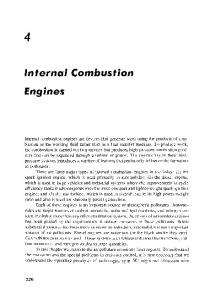
•A Dynamometer is load device used to measure an engines torque and speed. We often measure Fuel Consumption, Emissions and other parameters as well. •A dynamometer can also be used to control the speed of the engine by varying the load placed on the engine. •Dynos are often used to test different engine designs at the same load settings (Torque and Speed) for comparison purposes. •We want to test the engine under conditions similar to the actual conditions (speed, torque) in the field, or even “simulate” an actual drive cycle with the dynamometer 9
Dynamometers There are 2 basic kinds of dynamometers: Absorption Dynamometers These are devices that absorb the mechanical power from the test engine.
Transmission Dynamometers These are basically torque measurement devices placed in a power transmission link (ie. a shaft). They can be used to measure torque and speed, and thus power.
We will consider only Absorption dynamometers here.
10
Dynamometers All Absorption Dynamometers share some basic features: The shaft is connected to a Rotor housed in a Stator. There is some form of coupling (mechanical, hydraulic, aerodynamic, electromagnetic) between the Rotor and Stator. Equal and opposite torques are induced on the Rotor and Stator: Stator
Coupling Medium
Force on Stator
Rotor Rotation
Shaft
Force on Rotor
Force Measurement Device (Load Cell) 11
Various Dyno Designs There are many different designs used in dynamometers. Here are the most common ones (discussed below):
Frictional (Break) Hydraulic Generator Eddy current Fan Vehicular Motored Dynos 12
Frictional (Prony Break) Dyno The shaft spins a disk or drum. A break pushes a frictional lining against the disk, resisting rotation. The force on the break is equal and opposite to the force on the disk. Sometimes a rope is wound around the drum as a break.
Break
Force on Break
Force on Disk
Disk
Rotation
Rotation
Break
13
Hydraulic Dyno The shaft drives the impeller of a pump. The working fluid is pumped through a hydraulic circuit including a throttle valve. Hydraulic drag resists motion of the impeller. The throttle valve must be adjusted to vary the mechanical load. Hydraulic dynamometers typically have the highest power densities.
Pump
Shaft
Inlet Reservoir
Valve
14
Generator Type Dyno The shaft spins the rotor of a generator. As electrical load is applied to the output of the generator, an electromagnetic force resists motion of the rotor rotation. The load is usually a resistor bank (heater) either air or water cooled. Generally the field winding current is controlled to vary the mechanical load. Field Windings Generator
Rotation
Power Supply
Stator Windings Heater
Water Tank 15
Eddy Current Dyno The shaft spins a disk located inside a housing containing large electromagnet coils. When current passes through the coils they create a strong magnetic field in the disk. This creates “eddy currents” in the disk, which resist rotation, creating a torque between the housing and the disk. Varying the current varies the torque. Electromagnet
Force on Disk
M
Eddy Current
Rotation
Coil Current
Force on Coil
Rotation 16
Eddy Current Dyno Current is typically 1 to several amps, at 50 to 200 Vdc. The response is almost instant. These dynos are the easiest to control and quickest to respond.
17
Fan Dynamometer The shaft spins a fan which moves air. The fan must be calibrated on a frictional dynamometer before use, and its load is a function of temperature, barometric pressure and humidity. Torque goes as the square of the shaft speed. These dynos are typically not adjustable, but are very inexpensive.
2.5
1000 900 Torque = 1E-06 RPM
2.0
1.83
Fan Power (W)
700 1.5
600 500
1.0
400 Power = 1E-07 RPM
300 200
2.83
Fan Torque (Nm)
800
0.5
100 0 0
500
1000
1500 2000 Engine Speed (rpm)
2500
3000
0.0 3500
18
Fan Dynamometer Fans have 2 orientations: High load (normal) and low load (reversed). In the Normal orientation it efficiently pumps air, dissipating more energy. In Reversed orientation the blades move less air because they are less efficient. So there are 2 possible load curves:
Air Flow
Normal Rotation
Air
Reversed Rotation
During calibration the air flow should be blocked similar to what it will be during use Dummy cowling Test Frictional Air Flow Air Flow Dyno Engine 19
Fan Dynamometer Torque Curve from same fan in Normal and Reversed orientations 2.50
Fan Torque (Nm)
2.00
Normal Rotation
1.50
1.00
Reversed Rotation
0.50
0.00 0
500
1000
1500
2000
2500
3000
3500
Fan Speed (rpm )
20
Vehicle Dynamometer A vehicle may be weighed and instrumented to measure speed and acceleration. Knowing the acceleration and velocity of the vehicle and the gear ratio we can calculate the torque and speed of the engine. This technique requires a large area for testing and is usually only used for coarse measurements of maximum engine power/torque. This is a good way to confirm engine level testing.
T 1 , V1
T 2 , V2
A = (V2-V1)/(T2-T1) F=MxA T=RxF
21
Vehicle Dynamometer This “Torque Sprocket” is a type of transmission Dynamometer. As torque is transmitted through it the inner and outer races (which are separate) rotate relative to one another. This shift can be sensed by a speed pickup placed near by as the sprocket rotates. This allows simultaneous recording of both speed and torque on a moving vehicle. It is therefore a type of vehicle dynamometer.
1
No Load
2 3 Loaded
22
Motored Dynamometers A dynamometer which also has the ability to drive the test engine is called a “Motored dynamometer”. This is useful for measuring the friction of an engine. Generally the dynamometer spins the engine (which is not firing) and the torque on the motor is measured. The motor may be integrated with the load device, such as a motor/generator combination which can operate in either absorbing (ie. like a normal dyno) or driving mode (ie. a frictional dyno).
Separate “frictional” dynamometers exist which are solely for the purpose of measuring the frictional load of test engines. These are usually similar to the generator type dynamometers but with a large electric motor instead of a generator.
23
Motored Dynamometers This is a 3-Phase electrical motor suspended on bearings, and connected to a load cell. It is used to measure the friction of various engines and components as a function of velocity as well as operating conditions of the components.
Load Cell
Output Shaft
Motor
24
Comparison of Dyno Designs Frictional (Break)* Oldest design. Hard to control. Wear on frictional surfaces is a problem.
Hydraulic Highest power in smallest package (pump).
Generator* Inexpensive and easy to control. Fairly large for a given power.
Eddy current* Easiest to control. Low Inertia and bearing losses.
Fan* Very inexpensive. Needs careful calibration. Less accurate.
Vehicular* Requires measurement of vehicle mass. Ignores air drag. Good for vehicular studies.
* Indicates that we use this type of Dynamometer in our lab here at USM 25
Mechanical Details Engine Dynamometer Couples directly to the engine No gearbox or transmission Engine speed = Dyno speed
Dyno
Engine
26
Mechanical Details A Dynamometer may also be coupled to the output of a transmission or gear box. Speed and Torque of the engine and dyno are different by the gear ratio (Speed ↓, Torque ↑).
Engine
Transmission (gear box) Dyno
27
Mechanical Details A Chassis Dyno is driven from the vehicles wheels. The vehicle is mounted so the drive wheels are on a large roller, and locked down so it can not move. The dyno is connected to the roller, either directly or through a transmission of its own. Driven Wheel
Roller
Dyno 28
Mechanical Details Chassis dynos are used for testing of in-use vehicles with out requiring disassembly or modification of the vehicle.
Foto: Wikipedia
29
Mechanical Details: Coupling A coupler is used to connect spinning shafts to compensate for misalignment. U (Universal) Joints “X” shaped bearing configurations at both ends of a shaft. Common on drive shafts of rear-wheel drive vehicles. The 2 ends should be “offset” somewhat to avoid wearing a flat on bearings. These must be used in pairs (single joint velocity not constant)
30
Mechanical Details: Coupling CV (Constant Velocity) Joints Similar to U-joints but single joints have constant velocities. These are common components on front-wheel drive and 4-wheel drive vehicles.
Foto: Torvec.com
31
Mechanical Details: Coupling Sprocket Simple “quick-connect” for existing sprocketed systems (like motorcycles) Allows misalignment due to “slop” between fingers and sprocket teeth
32
Mechanical Details: Coupling Belt/Chain Allows for misalignment and can incorporate a gearing ratio as well We will use this between the chassis dyno roller and the dyno.
33
Mechanical Details Bearings The body of the dynamometer must be free to rotate, so it is supported on bearings.
Bearings suspending Generator Housing
34
Mechanical Details Load Cell Mounting The rotation of the dynamometer housing is resisted by a load cell which measures the force. The Load cell should be loaded in only one direction (ie. axially) to avoid biasing the output. Generally the load cell is mounted so the force is perpendicular to the axis of the shaft.
Load Cell mounts via ball-joint ends
35
Equations Torque = F x R Power = T x w w = RPM * 2 pi /60 Transmission: T2 = T1 x Ratio w2 = w1 / Ratio Spur gear losses (per stage) ~2% Tire losses ~ 10% Chassis or Vehicular Dyno typically reads 15-25% less than engine dyno due to transmission losses. 36
Operator Lights
Dynamometer Test Schematic
Display
Controller The controller tries to maintain the dynamometer at the proper speed, while the operator maintains the proper torque, and the Technician runs the data recording devices.
Fuel Meter Load Cell
Coil Power
Throttle Technician
Coil Speed Engine Cycle Operator
Dynamometer Pump Coolant Reservoir 37
DEMO: Magtrol Dynamometer In this demo we will demonstrate the measurement of speed and torque, unit conversion and calculation of power.
38
Part 2: Testing
39
Testing Commonly Measured Parameters Torque Speed Fuel Consumption Emissions Temperatures (Head, Exhaust, coolant)
Occasionally Measured Parameters Combustion Pressure Ignition Timing Dynamics (accelerations, vibrations, stress) Knock Intake/Exhaust Pressures Valve Lift Acoustics
These parameters can be measured manually or automatically. We will be focusing exclusively on automatic (computer assisted) measurements. 40
Cycle Averaging Data Typically averaged: Speed, load, throttle, Temps Some parameters are averaged over several cycles. Often the signals are “low pass filtered” to remove higher frequency fluctuations. For example Torque is negative during the compression stroke, and positive during the power stroke. What we’re interested in is the average torque output of the engine.
This can be done electronically or in code in a data acquisition system.
41
Electronic Averaging Electronic averaging (low pass filter):
Input Signal
R
Filtered Output
C Vaverage
The time constant is 1/RC. For a 6000 rpm signal (100 Hz) we would want to low pass at