when exploring and mapping unknown worlds. We call our approach \just in time sensing" because it uses the more accurate but constrained laser range sensor ...
Just-in-time sensing: e�ciently combining sonar and laser range data for exploring unknown worlds Gregory Dudek1 Paul Freedman2 Ioannis M. Rekleitis1 1 Centre
for Intelligent Machines, School of Computer Science, McGill University, 3480 University St., Montreal, Qu�ebec, Canada H3A 2A7 2
Centre de recherche informatique de Montr�eal 1801 McGill College Avenue, Suite 800, Montr�eal Qu�ebec H3N 2N4
Abstract This paper describes an approach to combining range data from both a set of sonar sensors as well as from a directional laser range nder to e�ciently take advantage of the characteristics of both types of devices when exploring and mapping unknown worlds. We call our approach \just in time sensing" because it uses the more accurate but constrained laser range sensor only as needed, based upon a preliminary interpretation of sonar data. In this respect, it resembles \just in time" inventory control which attempts to judiciously obtain materials for industrial manufacturing only when and as needed. Experiments with a mobile robot equipped with sonar and a laser range nder demonstrate that by judiciously using the more accurate but more complex laser range nder to deal with the well-known ambiguity which arises in sonar data, we are able to obtain a much better map of an interior space at little additional cost (in terms of time and computational expense). 1
1 Introduction
This paper describes an approach to combining range data from both a set of sonar sensors as well as from a directional laser range nder to e�ciently take advantage of the characteristics of both types of devices when exploring and mapping unknown worlds. We call our approach \just in time sensing" because it uses the more accurate but constrained laser range sensor only as needed, based upon a preliminary interpretation of sonar data. In this respect, it resembles \just in time" inventory control which attempts to judiciously obtain materials for industrial manufacturing 1 Appeared in \IEEE, International Conference in Robotics and Automation", v.1, pp 667-671. Apr. 1996.
only when and as needed. Sonar sensing is ubiquitous on mobile robots due to its low cost, the simplicity of the required processing, and the rapidity with which it can return results re ecting range measurements over a large region of space. Despite these advantages however, it su�ers from several shortcomings as a source of range data. Most importantly, the measurements tend to have low spatial resolution and the observed data (with most interpretation strategies) are typically confounded by the e�ects of multi-bounce specular re ections. For this reason, the use of sonar is often con ned to collision avoidance rather than mapping. Laser range sensors, on the other hand, are typically able to obtain comparatively accurate data with fewer artifacts when compared to simple sonar sensors. The laser range nder we have developed is based on BIRIS [3] technology: a special lens with two pinholes near the nodal point is used. This produces a double image of objects in the scene with a disparity that depends directly on the distance of the object from the focal plane of the lens. We obtain a stereo image using only a single CCD array. By projecting a laser stripe onto the scene, a target is made available which can be used for unambiguous stereo correspondence, allowing true depth to be readily computed. Two of these BIRIS sensors mounted on pan tilt units in a speci c con guration comprise the McGill QUADRIS sensor platform. Like all sensing technologies, the BIRIS sensor also has disadvantages. Its primary shortcoming is that although the accuracy of range measurements is reasonable over short distances (up to one or two meters), accuracy degrades rapidly with longer distances (this is one of the design parameters). Furthermore, obtaining either a dense range image or range data over a
wider eld of view than the 25 degrees or so covered by a typical camera2 lens implies physically sweeping the camera and laser across the scene, and hence involves a time delay. Early work to validate our \just-in-time" sensing strategy using real sonar data and simulated BIRIS data was reported earlier [8]. In this paper, we describe results using real sonar data and real BIRIS data obtained from the McGill QUADRIS platform.
1.1 Background Various approaches have been considered for the exploration of unknown or quasi-known environments. Most work dealing with real noisy sensor data must cope with the management of sensor uncertainty and exploration strategies, i.e. selecting successive unknown locations or objects to visit (investigate) e.g. [15, 17, 1, 6, 2]. The best way to manage exploration in the face of real sensor noise remains an open problem. The question is further complicated by the fact that the choice of an optimal mapping strategy is sensitive to the speci c task at hand. A somewhat distinct research stream deals with the complexity issues in autonomous robot exploration of an unknown environment [4, 11, 16, 12]. In general, work on sensor fusion has tended to focus on issues of how best to combine measurements from di�erent sensors e.g. [18, 5], or how best to extract data with a single sensor and fuse the measurements over time e.g. [9, 10, 19], rather than how to selectively extract measurements from di�erent types of sensor. This later problem of combining measurements over time has, in fact, two variants: that problem of fusing a set of measurements obtained somehow over some time period e.g. [14, 7], and the problem of ef ciently selecting where or when to obtain additional measurements e.g. [21]. An apparently general nding is that the di�culty of the exploration task is rather sensitive to the level of sensor noise and the delity of the geometric inferences made about the objects in the environment. Thus, it seems appropriate to focus some e�ort on e�ciently obtaining good geometric models since using all of the sensors on the robot all of the time can lead to serious ine�ciencies in exploration/mapping time and in using the on-board computational resources. 2 Using cameras with a very wide eld of view leads to distortions and a loss of resolution and thus is not an acceptable solution.
2 Just in time sensing
2.1 The Exploration Context: An Art Gallery
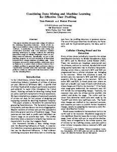
As an expermental testbed for our sensing methodology, we are examing the performance of our approach in an indoor environment resembling an art gallery or museum; such an environment has certain practical advantages as speci ed below. The environment consists of a large enclosed room containing several stationary objects. We make the assumption that a collision-free paths exists between any two points within the free space of the room. Although, the objects inside a room are assumed to be static, the con guration of the room is subject to change between successive visits by the robot and must therefore be mapped again every time it is visited. The oors are at (except for some well de ned places where stairs exist) and smooth without any anomalies. Our robot, an RWI B-12, is equipped with a ring of sonar sensors which provide coarse range measurements of distances up to 8 meters omnidirectionally, and a BIRIS sensor system that can give accurate estimates over at short range and only in one direction; see Figure 1.
Figure 1: RWI mobile robot equipped with McGill QUADRIS sensor platform. In this paper we will also ignore the issue of odometry errors. In practice this is a signi cant issue and we can address it is a variety of ways [13, 9].
2.2 Processing sonar data
As previously mentioned, a primary robot sensor is the sonar range nder. Our RWI robot is equipped with a ring of 12 sonars positioned equidistantly around it, returning 12 measurements at the same time. In order to obtain a denser range map which is less susceptible to artifacts, the robot is commanded to rotate in place
and more measurements are made. More precisely, we collect a total of 180 sonar measurements at each robot (x,y) position but not all of them are used. But as described above, multiple bounces or echos associated with sonar data may give rise to the following errors. Firstly, a phantom \third" wall may appear where two walls meet at a corner. Secondly, false measurements may be obtained suggesting the presence of objects far away. In some cases, errors such as these can be eliminated. Incompleteness and noise in sonarbased maps is, however, di�cult to avoid completely. In order to deal with such errors in the sonar data, certain measurements are suppressed from further processing. Firstly, measurements (range estimates) beyond a certain \logical" distance are discarded, under the assumption that they may not be reliable. Although this could result in the loss of legitimate information, we assume that such information is su�ciently distant from the robot as to be of little importance in mapping that part of the environment which is nearby. A second criterion for discarding erroneous sonar data is related to knowledge about the immediate surroundings of the robot. From knowledge of likely objects we know we can reliable detect any object within a circle of diameter 1m about the robot Consequently, any prior or subsequent range measurement within this circle can be assumed to be in error, and therefore is discarded. Once those measurements deemed to be in error are discarded, the sonar data measurements are then clustered together using the \Sphere of In uence Graph" [20]. Assuming a minimum distance in order to avoid clustering points at the same position as separate small clusters. Line segments are then t to the data clusters by splitting and merging them using a certain con dence measure to obtain new line segments with a certain con dence [MD94]. From that point on, the construction of the environmental map is performed in terms of lines with a con dence measure attached to them.
2.3 Processing laser range data
In order to improve the results we obtain from pure sonar data, the BIRIS laser range nder is judiciously called into play, according to our \just-in-time" sensing strategy. As previously described, the useful range of BIRIS is about three to four meters but in order to assume very good accuracy, most of the scans are performed at one and a half meters range. Another limitation is its eld of view of 25 degrees, which is, in practice, even smaller due to artifacts appearing at the edges of the scan lines. The BIRIS sensor may be used to obtain up to 512 range measurements per scan
whenever something is present (an object or a series of objects) in the whole eld of view. Once again, the \Sphere of In uence Graph" is used to cluster measurement data into clusters but this time, no minimum distance threshold is used, since the data points are already closer together. When line segments are grouped into clusters, we have observed almost ideal con dence levels. Note too that when BIRIS is used in addition to sonar, a third criterion for discarding sonar data in error may be de ned as follows. Whenever a line segment is observed by BIRIS, we assume that no object is present inside the triangle formed by the BIRIS line segment and the position of the robot at the apex. Moreover, as we shall see, BIRIS is only used in places where sonar is ambiguous, i.e. where much sonar data is error.
2.4 Just-in-time BIRIS sensing
We now describe the way in which the mobile robot explores and maps its unknown environment with justin-time BIRIS sensing to complement sonar sensing. Simply, BIRIS data is only acquired to accurately pinpoint the corners and the borders of objects, where the sonar data is ambiguous. The exploration strategy developed as a testbed for the fusion of sonar and laser data is a form of wall following, or more accurately, \closest object following". The world is modeled in terms of line segments with marked endpoints; an endpoint is marked as either \terminal" (con rmed) or \non terminal" (to be con rmed). The algorithm for exploration is outlined next. The robot explores its unknown environment by proceeding to the nearest object (or wall). (When multiple objects are present in the same sonar scan, the robot applies a modi ed breadth rst search algorithm in order to structure the way in which it will explore one object after another.) The robot then navigates around the object while increasing the length of the current line segment until reaching a non-terminal endpoint of the current line segment in a trajectory parallel to it at a distance of approximately one meter from it (making, if necessary, the proper adjustments). It is at this stage that BIRIS is used. Non-terminal endpoints will arise when the robot is approaching the corner of two walls whereby the current object (the wall that the robot was following) comes to an end. The robot localizes the potential corner using sonar data, aims BIRIS at the corner, and then maps the corner accurately, marking the endpoints of the two lines as terminals, i.e. the end of the wall that the robot was following, and the beginning of
the other wall. When the robot reaches the physical extremity of a line/wall, BIRIS is needed to accurately map the endpoint position. This is because the endpoint critically de nes the geometry yet is especially hard to acuurately position using sonar. Once again, the robot aims BIRIS at the endpoint of the object currently marked as \non-terminal", obtains data, transforms the data into line segments, and then calculates the exact position of the endpoint while marking it as \terminal". When both endpoints of the closest object line segment are marked as terminal, then the robot moves away from until a new object, not fully explored (with at least one non-terminal endpoint) becomes the new closest object.
2.5 Constructing the map from sonar and BIRIS data
The incremental construction of the map of the unknown world takes into account the position and orientation of the line segments, their data source (sonar, BIRIS), and the con dence measure attached to them. In particular, the map consists of three types of lines: Sonar, for the line segments created using only sonar points; Biris, for the ones that use only BIRIS measurements; Complex, for the ones that appear after merging Sonar and Biris line segments. If two lines are almost parallel and their separation is less than a critical threshold d (in our experiments, d = 5cm), then they are merged. There are two di�erent cases for merging. The rst case is when there is one Sonar line segment and one Biris or Complex line segment. Since BIRIS is much more accurate than sonar, we project the Sonar line segment onto the Biris/Complex line segment. In all other cases, we merge two line segments by taking into account the con dence measure (f ) associated with each one, and its length (l ). If the two line segments intersect, then a new line segment passing through the point of intersection is created with slope m (Equation 1) where m is the slope of the line segment with the largest con dence measure (length multiplied by con dence). If the two line segments do not intersect, then we identify their two nearest endpoints and calculate a weighted midpoint using the same weights used for the slope, thereby creating a new line segment passing through the weighted midpoint with a slope m as described above. i
merging two line segments with one having an endpoint marked terminal. It is possible that when we map a Biris or Complex line having a terminal endpoint onto a Sonar line segment, the length of the sonar line segment will change, in order to preserve the position of the terminal endpoint. In this way, BIRIS data helps \clean up" the Sonar line segments by discarding erroneous points and by adjusting the lengths of the Sonar line segments. Every time the robot uses its sonar sensors or BIRIS range nder, it updates its map with new Sonar or Biris line segments, in order to decide how to continue to explore that part of the environment which is still unknown. In addition, the partially constructed map would also be useful for helping the robot return to a \home base" in case of sensor/BIRIS failure, low power problems, etc.
3 Experimental results
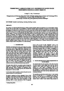
A set of experiments were conducted in the Mobile Robotics Lab of McGill's Centre for Intelligent Machines using the abovementioned RWI robot and specially developed running on a Silicon Graphics INDY workstation. At rst, just sonar was used to perform the world modelling in order to establish a baseline for comparison; see Figure 2. Note that the robot does not complete a full tour of the indoor space; just three walls are followed.
i
i
m = � � m + (1 ? �)m i
j
� = max( 1 +1 2 � f1 ; 1 +2 2 � f2 ) l
l
l
l
l
l
(1)
One di�culty arises when merging changes the position of line segment endpoints. Consider the case of
Figure 2: Map of our interior space generated using only sonar sensors. The same experiments were repeated for sonar and BIRIS, in order to demonstrate the improvement in accuracy. The following four gures are a sequence
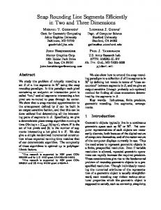
of \snapshots" during di�erent stages of the map construction of the same world, using \just-in-time sensing" with BIRIS. In Figure 3, we observe that the robot started its exploration at a slightly di�erent position and has now followed two walls; the portions in the gure shaded in grey indicate where BIRIS data was used to more accurately map corners.
Figure 4: Progressive map construction using just-intime sensing; Step B
Figure 3: Progressive map construction using just-intime sensing; Step A In Figure 4, partial information about the interior object and about a third wall has been added to the map. Note too that the artifact present in the lower left of the previous gure has been \cleaned-up" as part of the accurate mapping of the third wall. In Figure 5, we observe that BIRIS is used once again to more accurately map the corner associated with the end of the third wall and the beginning of the fourth wall. Finally, in Figure 6, the robot has completed the same partial tour as before (using just sonar), by following three walls. When compared to the map shown in Figure 2, we observe that the modelling is much cleaner, especially with respect to the interior (navigable) space, i.e. artifacts still remain \behind" the walls of the interior space but they have no bearing on the way in which the robot would use its map in the future to navigate within the world now explored.
4 Conclusions
This paper describes an approach to combining range data from both a set of sonar sensors as well as from a directional laser range nder to e�ciently take advantage of the characteristics of both types of devices
when exploring and mapping unknown worlds. We call our approach \just in time sensing" because it uses the more accurate but constrained laser range sensor only as needed, based upon a preliminary interpretation of sonar data. In this respect, it resembles \just in time" inventory control which attempts to judiciously obtain materials for industrial manufacturing only when and as needed. Experiments were also reported with an RWI mobile robot equipped with sonar (supplied by RWI) and a laser range nder we have developed at McGill University's Centre for Intelligent Machines based on BIRIS technology. They demonstrate that by judiciously using the more accurate but more complex laser range nder to deal with the well-known ambiguity which arises in sonar data, we are able to obtain a much better map of an interior space at little additional cost (in terms of time and computational expense).
References [1] Minoru Asada. Map building for a mobile robot from sensory data. IEEE Transactions on Systems, Man and Cybernetics, 37(6):1326{1336, November//December 1990. [2] Kenneth Basye and Thomas Dean. Map learning with indistinguishable locations. In M. Henrion L. N. Kanal J. F. Lemmer, editor, Uncertainty in Arti cial Intelligence 5, pages 331{340. Elsevier Science Publishers, 1990. [3] F. Blais and M. Rioux. Biris: a simple 3-d sensor. In Proc. SPIE 728, pages 235{242. International Society for Optical Engineering, 1990.
Figure 5: Progressive map construction using just-intime sensing; Step C [4] Avrim Blum, Prabhakar Raghavan, and Baruch Schieber. Navigating in unfamiliar geometric terrain. In Proc. 23rd ACM Symposium on the Theory of Computing, pages 494{504. ACM Press, 1991. [5] Paul B. Chou and Christopher M. Brown. Probabilistic information fusion for multi-modal image segmentation. In Proc. International Joint Conference of Arti cial Intelligence, pages 779{782, Milan, Italy, August 1987. [6] Gregory Dudek, Paul Freedman, and Souad Hadjres. Using local information in a non-local way for mapping graph-like worlds. In Proceedings of the Thirteenth International Conference on Arti cial Intelligence, pages 1639{1645, Chambery, France, August 1993. Internation Joint Conf. on Arti cial Intelligence Inc. [7] A. Elfes. Using occupancy grids for mobile robot perception and navigation. IEEE Computer, 22(6):46{58, June 1989. [8] Ioannis Rekleitis Gregory Dudek Paul Freedman. Mobile robot exploration by using fused data from two sensors. In PRECARN/IRIS Conference Vancouver, B.C., June 14-16, 1995. [9] Benjamin J. Kuipers and Y. T. Byun. A qualitative approach to robot exploration and map-learning. In Proceedings of the IEEE workshop on spatial reasoning and multi-sensor fusion, pages 390{404, Los Altos, CA, 1987. IEEE. [10] Simon Lacroix, Philippe Fillatreau, Fawzi Nashashibi, Raja Chatila, and Michael Devy. Perception for autonomous navigation in a natural environment. Worskhop on Comp. Vis. for space applications, 1993. [11] T. Levitt and D. Lawton. Qualitative navigation for mobile robots. Arti cial Intelligence, 44(3):305{360, August 1990.
Figure 6: Progressive map construction using just-intime sensing; Step D [12] Vladimer Lumelsky, Snehasis Mukopadhyay, and Kang Sun. Dynamic path planning in sensor-based terrain acquisition. IEEE Trans. on Robotics and Automation, 6(4):462{472, 1990. [13] Paul MacKenzie and Gregory Dudek. Precise positioning using model-based maps. In Proceedings of the International Conference on Robotics and Automation, San Diego, CA, 1994. IEEE Press. [14] H. Moravec. Sensor fusion in certainty grids for mobile robots. In A. Casals, editor, Sensor Devices and Systems for Robotics, NATO ASI Series, Vol. F52, pages 253{276. Springer-Verlag, Berlin, 1989. [15] P. Moutarlier and R. Chatila. Incremetal environment modelling by a mobile robot from noisy data. In Experimental Robotics 1, pages 327{346. Springer-Verlag, 1990. [16] B. Oommen, S. Iyegar, S. Nageswara, S. Rao, and R. Kashyap. Robot navigation in unknown terrains using learned visibility graphs, part i: The disjoint convex obstacle case. IEEE J. of Robotics and Automation, 3(6):672{681, 1987. [17] Y. Roth-Tabak and T. Weymouth. Environment model for mobile robotics indoor navigation. Technical Report CSE-TR-53-90, The University of Michigan, 1990. [18] S. Shafer, A. Stentz, and C. Thorpe. An architecture for sensor fusion in a mobile robot. In IEEE Int. Conf. on Robotics and Automation, pages 2002{2011, 1986. [19] Jun Tani. Model-based learning for mobile robot navigation from the dynamical systems perspective. IEEE Trans. System, Man and Cybernetics, 26(6), 1996. [20] Godfried Tousaint. A graph-theoretical primal sketch. Computational Morphology, 1988. [21] Peter Whaite and Frank P. Ferrie. Uncertain views. CVPR, 1992.