E-mail: {psurya,umarani,pg}@cse.iitk.ac.in ... map of an off-line created ear template is employed for ear ... Templates in their approach are created manually.
Proceedings of IEEE Int'l Workshop on Image Processing Theory, Tools and Applications, IPTA 2008, Sousse, Tunisia, pp. 1-8, Nov 2008.
Ear Localization from Side Face Images using Distance Transform and Template Matching Surya Prakash, Umarani Jayaraman and Phalguni Gupta Department of Computer Science and Engineering, Indian Institute of Technology Kanpur, Kanpur-208016, India. E-mail: {psurya,umarani,pg}@cse.iitk.ac.in
Abstract— The paper presents an efficient distance transform and template based technique for automatic ear localization from a side face image. The technique first segments skin and non-skin regions in the face and then uses template based approach to find the ear location within the skin regions. Ear detection proceeds as follows. First, edge map of the skin regions is computed and further processed to eliminate the spurious edges based on length and curvature based criterion. After getting the clean edge map, its distance transform is obtained on which ear localization process is carried out. Distance transform image of the edge map of an off-line created ear template is employed for ear localization. A Zernike moment based shape descriptor is used to verify the detections. The technique is tested on IIT Kanpur ear database which contains around 150 ear images and found to be giving 95.2% accuracy.
Keywords: Skin-segmentation, distance transform, ear detection, shape descriptor, Zernike moments. I. INTRODUCTION Biometric systems have become very essential components in almost all security aspects. These systems perform the recognition of a human being based on physiological and behavioral characteristics. Physiological characteristics are related to the shape of the body. Biometric traits such as face, fingerprint, iris, hand geometry fall under this category. Behavioral characteristics are related to behavior of a person. Signature, voice, character strokes etc. are some of the biometric traits which fall under this category. Among the various physiological traits, ear has gained much attention in recent years as it has been found to be a good and reliable biometrics for human verification and identification [1]. Reason behind the ear biometrics gaining popularity is that ears are remarkably consistent. Unlike faces, they do not change shape with different expressions or age, and remain fixed in the middle of the side of the head against a predictable background. To automate ear based recognition process, automatic ear localization is necessary but at the same time detection of the ear from an arbitrary side face image is a challenging problem. This is because of the fact that ear image can vary in appearance under different viewing and illumination conditions. In literature, there are very few techniques available for automatic ear localization [2], [3], [4], [5], [6], [7]. Burge and Burger [2] have used deformable contours for ear detection. Hurley et al. [3] have used force field approach to get the
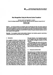
(a) Fig. 1.
(b)
(c)
(d)
Ear shapes: (a) Triangular, (b) Round, (c) Oval, (d) Rectangular
ear location. Their approach is only applicable when a small background is present. Chen and Bhanu [4] have presented a template based method for human ear detection from side face range images. The model template in this method is represented by an averaged histogram of shape index. This method works for 3D ear biometrics. Alvarez et al. [5] have proposed an ear localization method from 2D face image using ovoid and active contour model. Ear boundary in their method is estimated by fitting the contour of an ear in an image by combining snake technique and an ovoid model. This method requires an initial approximate ear contour as input and can not be used in fully automated ear recognition process. Ansari and Gupta [6] have presented an ear detection approach based on edges of outer ear helices. They exploit the parallelism between the outer helix curves of the ear to localize the ear. This technique solely relies on the parallelism between the outer helix curves and does not use any structural information present in the inner part of the ear, and hence fails if the helix edges are not proper. Moreover, finding parallel edges in an image is a computation intensive process. Yuan and Mu [7] have proposed an ear detection method based on skin-color and contour information. This method detects the ear by first roughly estimating the ear location and then improving the localization using contour information. This technique assumes the ear shape elliptical and fits ellipse to the edges to get the accurate position of the ear. The assumption of considering shape of the ear elliptical is not true for all persons and may not help in detecting the ear in general. For example, boundary of an ear of triangular shape can not be detected in this approach (Fig. 1(a)). In [8], Sana et al. have proposed an ear detection scheme based on template matching. To detect ears of different size, they maintain templates of various sizes. Templates in their approach are created manually
(b)
(a) Fig. 2.
(a) Edge map, (b) distance transform of (a).
by cropping the ears of different size from the side face images and template matching is performed for the wavelet decomposed template and side face images. In real scenario, ear occurs in various sizes and the preestimated templates are not sufficient to handle all the situations. Further, detection of ear using templates of various sizes and then selecting best detection is a very computation intensive task. This paper presents a novel technique for automatic ear localization from side face images using distance transform and template matching approach. The proposed technique is able to detect ears of different size and shape automatically from the side face image. It first segments the skin and nonskin pixels in the image and then computes the edge map of the skin areas. Length and curvature based edge pruning is applied to the edge map to remove the spurious edges which can not belong to ear. Distance transform images of the edge maps of face skin region and ear template are used in the ear localization process. The proposed technique applies a Zernike moments [9] based shape descriptor to verify the detections. Rest of the paper is organized as follows. Section II briefly presents a skin-color model, distance transform and Zernike moment which serve as the foundation for further discussion. In Section III, the proposed ear detection technique is discussed in detail. Experimental results are discussed in Section IV and conclusion is given in the last Section. II. PRELIMINARIES This section discusses some of the basic techniques which are required in developing the proposed ear localization model. Section II-A describes a skin-color model which is used for skin segmentation. Next section briefly gives the details of distance transform. Section II-C discusses Zernike moments based shape descriptor which is used for ear verification in the proposed technique. A. Color Based Skin Segmentation This section discusses a color based skin segmentation technique [10], [11] which is used in the proposed ear localization approach for skin segmentation. This technique takes a color image as input and segments skin and non-skin pixels in it.
The technique is adaptable to different skin colors and lighting conditions. Since RGB representation of color images is not suitable for characterizing skin-color, it first converts the RGB color space to chromatic color space [12], and then uses the chromatic color information for further processing. In RGB color space, the triple components (R, G, B) represent not only color but also luminance which may vary across a person’s face due to the ambient lighting and is not a reliable measure in separating skin from non-skin regions [10]. Luminance can be removed from the color representation in the chromatic color space, which is defined by a normalization process as follows: r = R/(R + G + B) b = B/(R + G + B)
(1)
It can be observed from Eqn. 1 that green color is redundant after the normalization as r + g + b = 1. The color distribution of skin colors of different people is found to be clustered in a small area of the chromatic color space. Although skin colors of different people vary over a wide range, they differ much in brightness than color. Because of this fact, skin-color model is developed in chromatic color space. Since color histogram of skin-color distribution of different people is clustered at one place in the chromatic color space, it can be represented by a Gaussian model N (µ, C), where mean µ and covariance C can be defined as: µ = E[x]
(2)
C = E[(x − µ)(x − µ)T ]
(3)
where x = (r, b)T and E[φ] denotes the expectation of the predicate φ. With this Gaussian fitted skin-color model, likelihood of skin for any pixel of an image can be obtained. If a pixel, having transformed from RGB color space to chromatic color space, has a chromatic pair value of (r, b), the likelihood P (r, b) of skin for this pixel can then be computed as follows: 1 exp[− (x − µ)C −1 (x − µ)T ] 2 2π|C|
P (r, b) = p
1
(4)
Likelihood values obtained using Eqn. 4 are used for skin segmentation. B. Distance Transform Distance transform [13] is computed normally for a binary image where each pixel in the binary image is assigned a number that is the distance between that pixel and the nearest nonzero pixel of binary image. Formally, for a binary image I, its distance transform image I d is given by the following equation: ½ 0, if (x, y) is a non-zero pixel I d (x, y) = (5) d, otherwise
(a) Fig. 3.
(b)
(c)
Skin segmentation: (a) Input Image, (b) Skin-likelihood Values, (c) Skin-segmented Image.
(n−|m|)/2
Rnm (ρ) =
X
(−1)s
s=0
×
(n − s)! ρn−2s , s!((n + |m|)/2 − s)!((n − |m|)/2 − s)! (6)
where n and m are non-zero integers, m subjected to the following constraints: n−|m| is even and |m| ≤ n. The (n, m) order of the Zernike basis function, Vnm (ρ, θ), defined over a unit disk is given by: Vnm (ρ, θ) = Rnm (ρ)exp(jmθ), ρ ≤ 1
(7)
The Zernike moment Znm of an image is then defined as: Z Z n+1 ∗ (ρ, θ)f (ρ, θ) (8) Znm = Vnm π unitdisk
Fig. 4.
Flow chart of the proposed technique
where, d is the Euclidian distance of pixel (x, y) to the nearest non-zero pixel. Fig. 2(b) shows an example of distance transform image for the edge image shown in Fig. 2(a).
C. Zernike Moments Among the family of moment invariants, Zernike moments are one of the most commonly used feature extractor and have been used in variety of applications [14], [15], [16]. In the proposed technique, Zernike moments based shape features are used for ear verification. In this section, the Zernike moment descriptor is presented. First, the definition of Zernike moment is given and then its properties are briefly reviewed. Zernike Moments Definition: In (ρ, θ) polar coordinates, the Zernike radial polynomials Rnm (ρ) are defined as follows [9]:
∗ where Vnm is the complex conjugate of Vnm . Popularity of the Zernike moments stems from the fact that they are robust in the presence of noise and exhibit rotational invariant property inherited from the angular dependence of Zernike polynomials. Also, Zernike moments provide nonredundant shape representation because of their orthogonal basis.
III. PROPOSED TECHNIQUE In this section, proposed ear localization technique is discussed in detail. First preprocessing steps are discussed followed by ear localization and ear verification. In preprocessing step, skin areas of the input side face image are segmented and processed for edge computation. Edges are further cleaned using edge length and curvature based criterion. Ear localization step creates a suitable size of ear template and performs the ear localization. Localized ears are verified using Zernike moment based shape descriptor at ear verification step. Fig. 4 shows complete flow chart of the proposed technique. A. Preprocessing 1) Skin Segmentation: The first step of the proposed technique is skin segmentation and detection of skin regions in the image. Main objective of detecting skin regions is to reduce the search space for the ear. Naturally, ears are in skin region and there is no point looking for them in non-skin regions.
(a) Fig. 5.
(b)
(c)
(a) Original edge image, (b) Edge image after length based edge pruning, (c) Edge image after curvature based edge pruning
Skin color model presented in Section II-A is used for skin segmentation. This model transforms a color image into a gray scale image (called skin-likelihood image) using Eqn. 4 such that the gray value at each pixel shows the likelihood of the pixel belonging to the skin. With an appropriate thresholding, the grayscale image is further transformed to a binary image showing skin and non-skin regions. A sample color image and its resulting skin-likelihood image are shown in Fig. 3(a) and Fig. 3(b) respectively. All skin regions in Fig. 3(b) are shown brighter than the non-skin region. Since people with different skins have different likelihood, an adaptive thresholding [11] process is used to achieve the optimal threshold value for each run. Fig. 3(c) shows a skin segmented image (in grayscale) for the image shown in Fig. 3(a). It can be observed from the result of skin segmentation that not all detected skin regions contain ear. Hence, ear localization can be performed to locate the ear in all these skin-like segments. 2) Erroneous Edge Pruning: After skin segmentation, edge map of the skin regions is obtained using Canny edge detector [17] and used for further processing. This edge map contains many spurious edges which may not belong to the ear. These edges are pruned using a criterion based on the edge length and curvature. Following discussion provides the details of these edge pruning criterion. Edge Length Based Pruning: In the edge length based pruning, all the edges having length less than a threshold are removed. If set E contains the edges from original skin image, new edge set E l after length based pruning is defined as follows: E l = {e|length(e) > Tl } (9) where length(e) gives the length of edge e ∈ E, which is defined as the number of pixels in the edge; and Tl defines the threshold for edge length. Edge length based pruning eliminates all the small spurious edges which generally arise due to noise or presence of hair. Fig. 5(a) shows an original edge image and Fig. 5(b) shows the edge image obtained after edge length based pruning. We can observe that the image shown in Fig. 5(b) does not contain many of the small spurious edges which are present in Fig. 5(a). Edge Curvature Based Pruning: As we can easily observe
that the edges which form the ear contain some curvature. That means, all the edges not having any curvature (or having curvature below certain threshold) can not be the part of the ear and can be eliminated. This observation is used to remove the edges which contain curvature below certain threshold. Let e = {vi |i = 1 : n} be an edge containing n pixels and vi = (xi , yi ) be the ith pixel. We use Average Absolute Curvature (AAC) [18] for curvature based edge pruning. For a continuous curve γ defined as γ : [a, b] → R2 , AAC is given as follows: AAC =
K(γ) L(γ)
(10)
R where K(γ) R= k(s)ds is the total absolute curvature and L(γ) = ds is the total length of the curve. For a discrete edge e, curvature can be approximated using the finite differences and length of the edge can be estimated by counting total number of pixels. So for the ith pixel in the edge, absolute curvature is defined as follows: k(i) = |(vi−1 − vi ) − (vi − vi+1 )|2 = |vi−1 − 2vi + vi+1 |2
(11)
So AAC for an edge e can be given as follows: n
eAAC =
1X k(i) n i=1
(12)
where, n is the number of pixels in edge e. Now new edge set E c after AAC based pruning can be defined as follows: E c = {e|eAAC > Tc }
(13)
l
where e ∈ E and Tc defines the threshold for AAC. Fig. 5(c) shows an edge image obtained after edge curvature based pruning. We can notice that it does not contain any linear (or close to linear) edges which are present in Fig. 5(b). B. Ear Localization Next step after computing the edge map of the skin regions is ear localization. Ear localization involves four steps: ear template creation, resizing of the ear template, distance transform computation and localization of the ear. Ear template creation is an off-line process and carried out beforehand.
Resizing of the off-line created ear template is done in accordance with the size of each input image and resized template is used for ear localization. Algorithm 1 describes the steps of ear localization and verification processes. 1) Ear Template Creation: For any template based approach, it is very much necessary to obtain a template which is a good representative of the data. In the proposed technique, ear template is created by averaging the intensities of a set of ear images. The set includes ear images of men and women. These images are selected from the IITK ear database. Human ear shape can broadly be categorized into four classes: triangular, round, oval, and rectangular. Fig. 1 shows the various shapes of the human ear. For the creation of ear template in the proposed technique, all types of the ears are considered to obtain a good template. Ears from the selected images are cropped and resized to same size. The ear template T is estimated by taking the mean of the pixel values of all ear images and formally defined as follows: T (i, j) =
N 1 X Ek (i, j) N
(14)
k=1
where N is the number of ear images used for ear template creation and Ek is the k th ear image. Ek (i, j) and T (i, j) represent the pixel values of the (i, j)th pixel of Ek and T respectively. In our experiments, we have used 20 ear images of various shapes to create ear template. To handle the detection of ears of different size, ear template is resized. 2) Resizing Ear Template: Resizing of ear template is an important step. As we know, ear in a side face image may occur in different size depending on the distance of the camera from the person. Not only this, some people may have small or large ear too. So to handle the detection of ears of various size, ear template need to be resized to make its size appropriate for the detection of ear from an image. An experiment has been performed and size of the side face image and the ear contained in it have been measured for 20 images taken from a digital camera from various distances for different people. It is observed that the size of the ear is proportional to the size of the side face image. This observation is used for resizing the ear template in the proposed technique. Size of the side face is estimated using the bounding box of the face skin region. In the proposed technique, resizing of the template is performed as follows. A reference side face image is considered whose ear size is same as the standard ear template size (120 × 80 pixels in our case). To obtain a suitable resized ear template for an input side face image, first its skin segmentation is performed. Segmented image is then used to get the size of the side face. Let, wif and wrf be the widths of the input face image and the reference face image respectively. If width of the ear of reference image is wre , width of the resized ear template for given input side face image is defined as: wie =
wre wrf
× wif
(15)
Algorithm 1 E AR L OCALIZATION AND V ERIFICATION 1: Determine ear template T using Eqn. 14 and obtain the distance transform image (T d ) of the edge map of T. 2: Compute the distance transform image (I d ) of the edge image of face skin regions. 3: Estimate normalized cross-correlation (NCC) at each pixel (x, y) of the image I d using template T d and Eqn. 16. 4: Let Π be the set containing all possible candidates of ear. 5: for each pixel (x, y) ∈ I d do 6: if N CC(x, y) > threshold1 then 7: Add (x, y) to set Π. 8: end if 9: end for 10: Arrange the elements of set Π in non-increasing order of their NCC values. 11: Let Ω be the set containing true ear location. 12: Set earDetected flag FALSE. 13: while (earDetected flag is FALSE) do 14: Consider each pixel (x, y) ∈ Π in the order. 15: Estimate distance(x, y) using Eqn. 17. 16: if distance(x, y) < threshold2 then 17: Add (x, y) to set Ω. 18: Set earDetected flag TRUE. 19: end if 20: end while 21: if earDetected flag is TRUE then 22: Display ear detection at location acquired in Ω. 23: else 24: Display “No ear detected.” 25: end if
By keeping the aspect ratio of the ear template same, it is resized to the width obtained in Eqn. 15. Resized template is employed for searching of the ear in the given input image. Resizing of the ear template in the proposed technique is done using the width of the side face image because width is less affected by the false face pixels (false face pixels are those skin pixels which are segmented as face pixels but actually they are not, e.g. pixels belonging to neck region etc.). Height of the side face is difficult to measure as it is often inaccurate because of the inclusion of the skin pixels of neck portion in the side face image. 3) Distance Transform Computation: In place of using directly the edge information or the gray level images of face and ear template, distance transform is used in localization as it contains optimum meaningful information about the neighborhood of a pixel. Distance trasform has been successfully used in many computer vision applications [19], [20], [21], [22]. After getting the distance transforms of the edge maps of the face and ear template, cross-correlation based searching is applied to locate the ear from the side face image. 4) Localization: Once the distance transform (T d ) of resized ear template edge image is created, it is used for the localization of the ear from the side face image. To search an
for detected ear) is estimated to validate the claim. To measure the similarity, Euclidian distance between the two sets of Zernike moments is estimated as follows: v u L uX distance = t (|MiT | − |MiE |)2
(17)
i=1
Fig. 6.
Some of the ear images used for ear template creation.
ear in the image, T d is moved over the distance transform of the face skin edge image (I d ) and Normalized Crosscorrelation Coefficient (NCC) [23], [24] is computed at every pixel. NCC at point (x, y) is defined as follows: N CC(x, y) = P d [I d (u, v) − I¯x,y ][T d (u − x, v − y) − T¯d ] qP u,v d ¯d 2 P [T d (u − x, v − y) − T¯d ]2 u,v [I (u, v) − Ix,y ] u,v (16) where sum is performed over u, v under the window con¯ and T¯d d taining the template T d positioned at (x, y). Ix,y are the average of brightness values of the portion of the target image under the template and template image respectively. Normalized cross-correlation coefficient estimates the degree of linear dependence between the corresponding pixel brightness values being compared. Since the cross-correlation coefficients lie between −1.0 and 1.0, match ratings also lie between −1.0 and 1.0. When the match rating is typically above a preestimated threshold (threshold1 in Algorithm 1), we accept the hypothesis that an ear exists in the region. Otherwise, we reject the hypothesis. Value of normalized cross-correlation coefficient closer to 1 indicates a better match. This step accepts all the points having NCC value greater than the threshold as probable locations of the ear. These locations are sorted in non-increasing order according to their NCC values. Ear verification is applied to all these detection to validate the existence of the ear. C. Ear Verification To determine whether a detected ear is actually an ear or not, shape based ear verification is performed. Since small set of lower order Zernike moments [9] can characterize the global shape of an object effectively [25], these moments are used for ear shape representation in the proposed technique. As Zernike moments are complex number, only their magnitudes are considered for the shape representation. Similarity between the two sets of Zernike moments (one for template and another
E L where {MiT }L i=1 and {Mi }i=1 are the L Zernike moments used to represent the shape of ear template and detected ear respectively. Probable ear locations found in the previous section are considered one by one in non-increasing order of their NCC values. Lower order Zernike moments of the distance transforms of the edge images of the ear template and the detected ear are estimated and similarity distance between them is calculated using Eqn. 17. To get the distance transform image of the detected ear at point (x, y), template sized image is cropped from the input distance transform image of side face image keeping the point (x, y) at the center of the template. If the value of distance (estimated using Eqn. 17) is less than a preestimated threshold (threshold2 in Algorithm 1), detection is accepted, otherwise it is rejected.
IV. EXPERIMENTAL RESULTS Experiment is performed on IIT Kanpur ear database which contains total 150 side images of human face with resolution 640 × 480. These images are captured using a digital camera from a distance of 0.5 to 1 meter. To create ear template in our experiment, a set of side face images of 20 people is considered. These images include side face images of both men and women. Ears are cropped from these images and resized to 120 × 80 pixels. Ear images of all shapes viz. triangular, round, oval and rectangular are considered for template creation. Fig. 6 shows a few of the ear images used for the creation of ear template. Ear localization technique (based on Algorithm 1) is invoked on the input side face image which returns the ear location in case of successful ear detection and “failure” otherwise (when it fails to locate the ear), in which case manual cropping of the ear is done. In our experiments, we consider threshold1 = 0.5 and threshold2 = 0.3. Fig. 7 shows some of the results obtained using proposed technique. Ears of different size and shape are efficiently localized from the side face images. The proposed technique is also able to detect ear in presence of little occlusion due to hair. First three images in the last row of Fig. 7 show such examples. The accuracy of the localization is defined by: (genuine localization/total sample) × 100. The accuracy of the proposed technique is found to be 95.2%. Localization method has failed in some cases to localize ear correctly, especially for the images which are of poor quality or heavily occluded due to hair.
Fig. 7.
Ear detection results where detected ears are marked with rectangular boundary.
V. CONCLUSION This paper first reviews the existing ear localization techniques in the literature for automatic ear detection in 2D side face images and then proposes a novel technique for the same. The proposed technique detects ear automatically in the side image of human face without any user interaction and can be employed in an automatic ear based biometric system. It is effectively able to detect ears of different shape and size without any user intervention. Ear detection in the proposed technique is fast as it prunes almost 60% area of the side face image and searches for ear only in the skin areas. To detect ear in the proposed technique, three steps viz. preprocessing, ear localization and ear verification are followed. Preprocessing phase first segments skin and non-skin regions in the image and then computes the edge map of the skin regions. It also employs edge length and curvature based criterion to eliminate spurious edges from the edge map. Ear localization phase uses this skin regions edge map and runs a template based approach to localize the ear. Once ear is localized, a Zernike moment based shape descriptor is used to verify the detection. The proposed technique is tested on IIT Kanpur ear database containing side face images of 150 individuals and found to be giving 95.2% accuracy. The proposed technique can be extended for the detection of ear in noisy images and in the cases where ear is immensely occluded by the hair. R EFERENCES [1] B. Bhanu and H. Chen, Human Ear Recognition by Computer. Springer, 2008. [2] M. Burge and W. Burger, “Ear biometrics in computer vision,” Proceedings of International Conference on Pattern Recognition, ICPR’ 00, vol. 02, pp. 822–826, 2000. [3] D. J. Hurley, M. S. Nixon, and J. N. Carter, “Automatic ear recognition by force field transformations,” in IEE Colloquium: Visual Biometrics, pp. 8/1–8/5, 2000. [4] H. Chen and B. Bhanu, “Human ear detection from side face range images,” in Proceedings of International Conference on Pattern Recognition, ICPR’ 04, vol. 3, pp. 574–577, IEEE Computer Society, 2004. [5] L. Alvarez, E. Gonzalez, and L. Mazorra, “Fitting ear contour using an ovoid model,” in IEEE International Carnahan Conference on Security Technology, ICCST’ 05, pp. 145–148, 2005. [6] S. Ansari and P. Gupta, “Localization of ear using outer helix curve of the ear,” in Proceedings of the International Conference on Computing: Theory and Applications, ICCTA’ 07, pp. 688–692, IEEE Computer Society, 2007. [7] L. Yuan and Z.-C. Mu, “Ear detection based on skin-color and contour information,” in International Conference on Machine Learning and Cybernetics, ICMLC’ 07, vol. 4, (Hong-Kong), pp. 2213–2217, 2007. [8] A. Sana, P. Gupta, and R. Purkait, “Ear biometric: A new approach,” in Proceedings of International Conference on Advances in Pattern Recognition, ICAPR’ 07, pp. 46–50, World Scientific, Singapore, 2007. [9] R. J. Prokop and A. P. Reeves, “A survey of moment-based techniques for unoccluded object representation and recognition,” CVGIP: Graphical Models and Image Processing, vol. 54, no. 5, pp. 438–460, 1992. [10] J. Cai, A. Goshtasby, and C. Yu, “Detecting human faces in color images,” in International Workshop on Multi-Media Database Management Systems, IWMDMS’ 98, pp. 124–131, 1998. [11] J. Cai and A. Goshtasby, “Detecting human faces in color images,” vol. 18, pp. 63–75, December 1999. [12] G. Wyszecki and W. Stiles, Color Science: Concepts and Methods, Quantitative Data and Formulas. Wiley, 1982. [13] H. Breu, J. Gil, D. Kirkpatrick, and M. Werman, “Linear time euclidean distance algorithms,” IEEE Transactions on Pattern Analysis and Machine Intelligence, vol. 17, no. 5, pp. 529–533, 1995.
[14] K. W.-Y. and K. Y.-S. Signal Processing: Image Communication, vol. 16, no. 1, pp. 95–102, 2000. [15] S. Belkasim, E. Hassan, and T. Obeidi, “Explicit invariance of cartesian zernike moments,” Pattern Recognition Letters, vol. 28, no. 15, pp. 1969–1980, 2007. [16] M. Liu, Y. He, and B. Ye, “Image zernike moments shape feature evaluation based on image reconstruction,” Geo-Spatial Information Science, vol. 10, no. 3, pp. 191–195, 2007. [17] J. Canny, “A computational approach to edge detection,” IEEE Transactions on Pattern Analysis and Machine Intelligence, vol. 8, no. 6, pp. 679–698, 1986. [18] J. C. Lagarias and T. J. Richardson, “Convexity and the average curvature of plane curves,” Geometriae Dedicata, vol. 67, pp. 1–30, 1997. [19] D. W. Paglieroni, G. E. Ford, and E. M. Tsujimoto, “The positionorientation masking approach to parametric search for template matching,” IEEE Transactions on Pattern Analysis and Machine Intelligence, vol. 16, no. 7, pp. 740–747, 1994. [20] P. Tsang, P. Yuen, and F. Lam, “Classification of partially occluded objects using 3-point matching and distance transformation,” Pattern Recognition, vol. 27, no. 1, pp. 27–40, 1994. [21] M. Sanjay, S. Das, and B. Yegnanarayana, “Robust template matching for noisy bitmap images invariant to translation and rotation,” in Indian Conference on Computer Vision, Graphics and Image Processing, December 21-23, 1998, (New Delhi, INDIA), pp. 82–88, 1998. [22] D.-J. Lee, J. Archibald, X. Xu, and P. Zhan, “Using distance transform to solve real-time machine vision inspection problems,” Machine Vision and Applications, vol. 18, no. 2, pp. 85–93, 2007. [23] J. K. Aggarwal, L. S. Davis, and W. N. Martin, “Correspondence processes in dynamic scene analysis,” in Proceedings of the IEEE, vol. 69, pp. 562–571, 1981. [24] D. I. Barnea and H. F. Silverman, “A class of algorithms of fast digital image registration,” IEEE Transactions on Computers, vol. 21, no. 2, pp. 179–186, 1972. [25] C.-H. Teh and R. T. Chin, “On image analysis by the methods of moments,” vol. 10, no. 4, pp. 496–513, 1988.