ISWC '17, SEPTEMBER 11–15, 2017, MAUI, HAWAII, USA
HapticToolkit - Easily Integrate and Control Vibration Motor Arrays for Wearables Abstract Jan Thar RWTH Aachen University
[email protected]
Sophy Stoenner RWTH Aachen University
[email protected]
Florian Heller Hasselt University - tUL - imec fl
[email protected]
Jan Borchers RWTH Aachen University
[email protected]
Haptic input is a common input method for navigation aids for visual impaired people, leveraging an otherwise unused sensory channel depending on the body region, but building systems with large numbers of vibration motors is rather complex. For this purpose we developed a system to easily and quickly build systems with largen numbers of vibration motors. With only low requirements on manual skills as well as tools, such wearables with huge numbers of vibration motors can be reproduced, e.g., at a local Fab Lab or Makerspace.
Author Keywords e-textiles; wearable computing; construction kit;
ACM Classification Keywords B.4.m [Input/Output and data communications (e.g., HCI)]: Toolkit Permission to make digital or hard copies of part or all of this work for personal or classroom use is granted without fee provided that copies are not made or distributed for profit or commercial advantage and that copies bear this notice and the full citation on the first page. Copyrights for third-party components of this work must be honored. For all other uses, contact the Owner/Author. Copyright is held by the owner/author(s). ISWC’17, September 11–15, 2017, Maui, HI, USA ACM ISBN 978-1-4503-5188-1/17/09...$15.00 https://doi.org/10.1145/3123021.3123066
249
Introduction Several approaches using arrays of vibration motors to produce a tactile image on the human body have been presented before. From sparse ones (4 × 4 motors) as in [2], more broader ones like the one for gaming [1] with 4 × 12 motors, to a matrix of 16 × 8 motors as in [3] to directly
ISWC '17, SEPTEMBER 11–15, 2017, MAUI, HAWAII, USA
feel a depth image on the abdomen. While all these systems are reproducible, the amount of work to control large amounts of vibration motors and implement them into a wearable form should be reduced. Furthermore weight, power consumption and noise has to be reduced to be able to wear such a system.
Design considerations
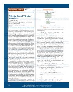
Figure 1: A belt with 16*8 vibration motors and a depth camera on the front side
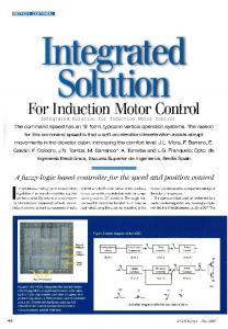
Figure 2: Detail: Wiring, 3D-printed clips, and PWM-I/O-expander boards
The toolkit has to simplify the design for wearable haptic feedback systems, it has therefore to be scalable to different layouts, easy to reproduce without special tools, and furthermore be cost sensitive and working reliably. We started testing several approaches for driving the vibration motors. The designs both for electronics as well as 3D-design-files can be found at 1 . Serial connection - WS2811 The WS2811 chip which is used to drive the popular LED stripes can be used in combination with an additional driving circuit (transistor and free wheeling diode) to drive a vibration motor. Either each color is replaced by a motor or a combination of motor and signal LEDs can be used. While driving the motors would be rather easy, e.g., using the existing libraries for WS2812, the electronic consists of multiple components. This increases costs and size, but the main disadvantage is the reliability of the system: If one board fails, the remaining boards that are logicaly behind it will also not work anymore. Parallel connection From a reliability perspective, having all motors with their logic circuits on a parallel bus system would be the most promising option, as long as the bus system itself it not damaged or short-circuited. Having a dedicated microcontroller for each motor results, again, in rather big and 1
https://github.com/JanThar/HapticHardware
250
expensive circuitry per motor. This can be reduced by driving multiple vibration motors with one board, partly negating the parallel set up (resulting in a combination of parallel bus and star topology). One minor advantage is also the possibility to drive the motors in more complex patterns due to the dedicated micro-controller, as well as having the possibility to use, e.g., linear resonant actuators instead of DC vibration motors. Still, the complexity to built the system from the electronic hardware side in large quantities, as well as the need to program each controller makes such a system only feasible for real mass production, not for self made singular wearables. I2C connection We therefore choose the PCA9685 as I2C-I/O-expander. It is used in the popular Adafruit servo driver board, therefore a large number of software examples exist, lessening the burden for programming. On the PCB we add driver circuits (ULN2803) for the vibration motors as well as an adjustable voltage converter. The address of each board is selected on the backside with solder jumper. Pads on the side are used to either directly solder wires or solder a pin header and then use wires with crimped connectors for easier adaption of the setup if required. Small indentations on the outer sides are used to fix a 3D-printed clip, which is used to attach the PCB to the fabric. Alternatively, holes can be used to sew the board directly on it. The resulting boards can be seen in Figure 2 on the right side, the PCB layout is shown in Figure 4. This design was the easiest to built with a low number of components, and it is reliable and scalable (from 16 motors with one board up to 992 with 62 boards on one I2C bus). Motors Instead of using standard DC vibration motors with external excenters we wanted to use one with an integrated excen-
DESIGN EXHIBITION
ter to reduce the size of an external housing. The common pancake vibration motors where not sufficiently reliable while performing a long test run of 48 hours, therefore we switched to less common encapsulated vibration motors, which are still easily and cheaply obtainable. These motors come with a standard ribbon cable as connection to the I2C boards.
Figure 3: Backside: Battery pack and processing unit
Assembly For an easy assembly of the belt, a rectangular hole is laser cut for each motor. A small 3D-printed housing (in two halves, see Figure 5) is then used to clip the motor into the hole. Similar clips are designed to hold the wires in place, as seen in Figure 2, for a clean design. The use of the clipping system reduces the need of sewing, and allows an easy change of components if necessary. All 3D-designs are made for 3D-prints without support material, allowing the use of basic 3D-printers without the need to manually remove a support structure afterwards. Camera, Processing and Battery For testing the system, we used a Intel RealSense camera together with an Up board as processing unit, which then controls the vibration motors over the I2C boards. Since Up board, camera, and I2C boards with integrated voltage regulators run on 5V, a common power supply can be used, again reducing complexity and access for everyday makers, who should be able to rebuild the system. Both Up-Board and Battery pack are mounted within 3d-printed housings at the backside, sewn onto the textile directly above the Velcro connector, as shown in Figure 3.
Building and evaluation
Figure 4: PCB-Layout
Instead of using a vest we choose to build a belt with 16 × 8 motors as in [3]. The number of motors results in a 4 cm spacing between these, being close to the distinguish-
251
able resolution of the human abdomen. On the other hand, the use of 16×PWM-I/O expanders to drive them allows a simplified setup with this number of motors. The belt form with all components included allows an easier testing setup with multiple people in short time, while it is also possible to wear the belt below clothing with only the small camera outside the clothing, rendering the whole system invisible. For the belt itself, we choose a more visible concept to highlight the technique from a design perspective, the whole system can be seen in Figure 7. Since nearly all components are clipped into (for convenience) laser-cut holes in the belt, a fast and precise assembly is possible and no special tools besides a 3D printer are required. The most complicated step is the assembly of the SMD-components on the driver boards. While it is possible to manufacture both the boards and populate them by hand, an automatic assembly or obtaining the board might be the easier way. For wearability at the backside, only flat sides of 3D-printed parts are in contact with the human body (see Figure 6). The used 3D-net mesh textile which is highly breathable and stretchable also improves wearability. Furthermore, the belt system allows to test the system with camera and vibration motors on the human back, to enable a person to feel what happens behind herself without looking back, e.g., as safety feature for industry 4.0. The belt was now in use on several fairs, proving the system to be simple to use (people walk around with closed eyes after few minutes testing), and both power consumption (roughly 6h with one battery pack, depending on the average distance to objects over time), and noise are within acceptable borders. Furthermore, the system runs reliably for more than 80h on faires alone, not considering testing phases before and in between without any fixes (besides software upgrades).
ISWC '17, SEPTEMBER 11–15, 2017, MAUI, HAWAII, USA
Building other wearables with haptic feedback
Figure 5: 3D-design motor clip
Figure 6: Complete system Body-side
Figure 7: Complete system
Designing another wearable with multiple vibration motors will still begin with choosing the right vibration motor. Depending on vibration duration and intensity, even pancake motors are possible, otherwise choose for the easiest setup with encapsulated motors. Optimally these do not come with wires but short springs as contacts for SMD mounting — these were the easiest to solder and most reliable in our experience. Next, adapt the 3D-printed motor casing if necessary. We will provide a customizable version for different motor sizes in a next step. Cutouts for the motors directly depend of the size of the housing, therefore they have to be adapted as well if needed. The vector graphic template provided shows the setup for our vest - for other wearables a basic outline from a picture or design file can be used. The cutouts for the motors are then placed at the desired places, then the cutouts for the PCBs on the sides are placed (one for 16 vibration motors). Finally, the wiring can be hold in place with additional cutouts for the cable clips. Thereafter, the cutouts are cut with a laser or by hand, the clips and housings are 3D-printed, and a number of PCB driver board assembled - each with a unique I2C address configured with a solder jumper on the backside. Each board connects to 16 vibration motors with wires, while 4 additional pins are used for I2C data connection with a central unit, and power line. All PCBs can be connected in parallel. The internal voltage regulator is set to the normal configuration for 3.3V vibration motors, other values up to 5V are also possible. This setup allows, as mentioned, the use of a normal 5V power bank, and only minor wiring with soldering wires at the vibration motors and crimped connectors (or soldering) at the other end is necessary. The PCB is designed for automatic assembly. Both 3D-printed clips and laser cut holes furthermore drastically reduce assembly time of the whole wearable and also allows easy maintenance.
252
Since the driver PCBs use the same I2C I/O expander chip as the Adafruit Servo motor boards, programming can be then done, e.g., with Adafruit’s library and examples for the Arduino, which allows an easy access for programming the setup for non-experts.
Design and Optic Overall the design is purely functional — eventually, the system should be covered with another layer of textile and become invisible. Therefore, all components are designed to be as easy as possible to produce with tools one can find in a local makerspace, if not at home. On the other hand, cable routing and motor and electronic mounting with 3dprinted clips allows a clean set up. Highlighting the clips with orange plastic produces a clearly visible structure, making the technical parts more visible for the audience, while both gray cables and textile stays in the background, which allows a good visibility for exhibitions, where a covered version would be almost invisible and not easy to understand for the user. Even with the visible setup, explanations are necessary, and for presentations an even more visible setup might be interesting, but out of scope of the toolkit.
Conclusion and Future Work The proposed setup allows building and controlling of wearable systems with large amounts of vibration motors. While the system is already proven to work stable, it has to be easier to adapt to different sizes/kinds of vibration motors to not be constrained to a single supplier. Main obstacle for everyday-users to built such a system might be soldering the PCBs by hand, which can be easily manufactured with a pick-and-place machine. All housings and clips are 3D-printable without support material, and laser cutting the textile (although not required) should also be possible with access to a Makerspace. Therefore, the resulting system
DESIGN EXHIBITION
can be used as easy prototyping base for wearables with haptic feedback and large numbers of vibration motors. For presentation on fairs we will add another layer with LEDs above the belt to visualize the vibration image for bystanders, with the reduced noise generation it is already hard to catch the functionality of the system without wearing it.
Acknowledgements This toolkit was funded by the German Federal Ministry of Education and Research as part of the Photonics Research Germany (13N14065). Special Thanks to David Anton Sanchez, who developed the first version of the vest.
REFERENCES 1. Sean Benson. 2015. 3D Haptic Vest for Visually Impaired and Gamers. (August 2015). https://hackaday.io/seanbenson 2. Dimitrios Dakopoulos, Sanjay K. Boddhu, and Nikolaos Bourbakis. 2007. A 2D vibration array as an assistive device for visually impaired. In Proc. of BIBE ’07. IEEE, 930–937. 3. Philipp Wacker, Chat Wacharamanotham, Daniel Spelmezan, Jan Thar, David A. Sánchez, René Bohne, and Jan Borchers. 2016. VibroVision: An On-Body Tactile Image Guide for the Blind. In Proceedings of the 2016 CHI Conference Extended Abstracts on Human Factors in Computing Systems (CHI EA ’16). ACM, New York, NY, USA, 3788–3791. DOI: http://dx.doi.org/10.1145/2851581.2890254
253