ECE 341 Introduction to Computer Hardware When and Where ...
Recommend Documents
A basic knowledge of network topology, channel access protocol, network traffic,
and ... Give an overview of computer networking and hardware fundamentals.
D.A. Patterson and J.L. Hennessy, Computer Architecture and Design: The
Hardware/Software Interface, 4 th edition, Morgan Kauffman Publishers. If you
cannot ...
Aug 20, 2009 ... Hardware Design with VHDL. Course Introduction. ECE 443. ECE UNM. 2. (8/20/
09). Course Goals. Simply stated, my objective is to teach you ...
ECE 341 – Electromagnetic Fields I, Fall 2013. COURSE SYLLABUS ... x < 80 C+
; 70 ≤ x < 77 C; 60 ≤ x < 70 D; x < 60 F;. (6) Exams: • Exam 1 ... Final Exam –
see the Fall 2012 Final Exam Schedule on the CSU web. All exams are closed ...
No Image. Download Full Version. #341+Where to Download: 'Rainforest Solitaire' Coupon ... Windows 95/98/ME,Windows NT/2
On this online store you will find every thing and everything to do with Rainforest ... Remove all cards by selecting op
CDA 3101: Introduction to Computer Hardware and. Organization.
Supplementary Notes. Charles N. Winton. Department of Computer and
Information Sciences.
near the publicity as computer hacking. • I'd like to ... EE Basics. – Basic
Electronic Components and what they do. • Cracking the case. – How to open up
...
ext: Computer Organization & Design (Patterson &. Hennessy). • 4th edition of the
textbook. • Not the ARM version (or the revised 4th edition?) • ou are expected ...
Feb 13, 2008 ... Computer Systems 2: Hardware Interfacing. 1. Introduction. In this chapter we will
look at how we can connect our computer to hardware, so we ...
ECE 114: Introduction to Computers and Programming. Instructor: Prof. Michael
Huang, CSB 414, Office hours (3-4:30pm, Th). Recitations: Fridays 12 noon ...
Winner will be notified via phone call and does not have to be present to win. Value of TV not to exceed $700. Winner wi
Mar 16, 2012 ... ECE 341 Probability and Random Processes for. Engineers ... 0 No other notes
or books are permitted. ... +5 and —5 with equal probability.
logic – Multiplexer and Demultiplexer basics - GRAY code – ASCII code
representation ... TMH 1997. 5.programming in ANSI C -E.Balagurusamy,Third
edition ...
One-click to Recover Lost Messages or Contacts from iPhone 6/5S/5/4S. * Hi there ... iStonsoft iPhone SMS+Contacts Recov
Good day, in the event you have landed on this webpage it is very quite likely that you were searching on where to buy J
Introduction to computers. 1. James Tam. Introduction To Computers: Hardware
and Software. In this section of notes you will learn about the basic parts of a.
Computer Organization and Design, by David A. Patterson and John L.
Hennessy. • Computer Architecture: A Quantitative Approach, by John L.
Hennessy and ...
Jun 2, 2013 - Business Mentors are here to help you out with any questions about ... Free WiFi will be provided at the v
Jun 2, 2013 - It is very important that you set up your team site, as this .... These phone numbers are your keys to the
Workstations - medium computer: Introduced in the early 1980s, workstations ....
manual process, starting with flow charts and paper notes, followed by detailed.
NAME. : Communication Networks-Fundamental Concepts and Key Architectures
... Modern Digital and Analog Communication Systems. AUTHOR : B. P. Lathi.
Material from or based on: The HCS12/9S12: An Introduction to Software &
Hardware. Interfacing, Thomson Delmar Learning, 2006. ECE 4510. 2. Chapter
10.
ECE 341 Introduction to Computer Hardware When and Where ...
ECE 341. Introduction to Computer. Hardware. Instructor: Zeshan Chishti zeshan
@ece.pdx.edu. Fall 2013. Portland State University. When and Where? • When: ...
ECE 341 Introduction to Computer Hardware Instructor: Zeshan Chishti [email protected] Fall 2014 Portland State University
When and Where? • When: Mondays and Wednesdays 4:40 - 6:30 PM • Where: EB 103 • Office hours: Mondays and Wednesdays after class, or by appointment • Webpage: http://ece.pdx.edu/~zeshan/ece341.htm • TA: Leela Kamalesh Yadlapalli • TA office hours: TBA • Go to the course webpage for: – Class slides – Course syllabus and schedule – Grading policies – Homework assignments and solutions
Course Information • Textbook: Computer Organization and Embedded Systems, 6th Edition, Hamacher, Vranesic, Zaky and Manjikian. McGrawHill, 2011. ISBN 9780073380650 / 0073380652 • Expected background: CS201 or equivalent – – – –
Basic knowledge of computer organization Data representation in binary, decimal, and hexadecimal notation Basic knowledge of instruction set architecture Assembly language programming
Grading Policy • Homeworks
35%
– 8 homework assignments, top 7 chosen for each student to contribute towards the 35%
Other Policies • All homeworks due in class. No extensions given • Submit homework to the instructor soon after entering the class • You can also submit homeworks via email before the start of class • Midterm exam in class during week 6
What this course is all about? This course is about designing a computer in hardware End Goal: To understand the hardware implementation of different components of a modern computer
Arithmetic and logic
Input
– Wednesday, November 5, 4:40 – 6:30 PM Memory
• Final exam will cover entire course with more emphasis on material taught after the midterm exam
Output
Control Interconnection I/O
Processor
Basic functional units of a computer
Course Topics • • • • • • •
Digital logic – gates, flip flops, multiplexers, state machines Computer arithmetic Basic computer architecture – data path, control, and buses Pipelining hardware CISC vs RISC architectures Memory hierarchy and virtual memory Input/output techniques – polling, interrupts, and DMA
Lecture # 1 DIGITAL LOGIC DESIGN
Lecture Topics
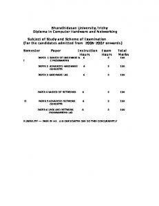
Logic Circuits • Example: Light bulb controlled by two switches
• Combinational Logic – Logic gates and logic circuits – Synthesis of logic functions – Logic expression minimization
Light Bulb
Pos. 0
Power Supply
Switch x1 Pos. 1 Pos. 0 Switch x2
• Reference: Appendix A of the textbook (pages 466-481), including sections A.1, A.2, A.3, and A.4, excluding A.3.1 and A.3.2
Pos. 1
Common Ground
• Input: Switch positions – Represented as binary variables x1 and x2 whose values can be either 0 or 1
• Output: Condition of light bulb – Represented as binary variable f with possible values 0 (off) or 1 (on)
• Logic circuit: Interconnection of switch terminals – Output=1 if a closed path exists from supply to the bulb through the switch network
OR function (Parallel Connection) 0
x1
x1
x2
f(x1,x2) = x1+x2
AND function (Series Connection) 0
1 0 x2 1
If either x1 or x2 is in the 1 position, the light is on (output = 1)
0
0
0
0
1
1
1
0
1
1
1
1
• OR function is represented by the “+” symbol: f = x1 + x2
• Extendible to n variables: f = x1.x2.….xn is equal to 1 if for all i, xi = 1
NOT function
XOR function (Exclusive-OR Connection) x1 0
x1
1
0
x2
x2
f(x1,x2) = x1 ⊕ x2
x
f(x) = NOT(x)
0
1
1
0
1
If x1 = x2 = 0, light is off (output = 0). Flipping any switch flips the output
0
0
0
0
1
1
1
0
1
1
1
0
• XOR function is represented by the “⊕ ” symbol: f = x1 ⊕ x2 • Basic properties of XOR operation:
NOT function complements (inverts) its input
• NOT function is represented by the “ “ symbol f =x • Important properties of NOT function: x =x
x1⊕x2 = x2⊕x1 ( x1 ⊕ x 2) ⊕ x3 = x1 ⊕ ( x 2 ⊕ x3) 1⊕ x = x 0⊕ x = x x⊕x =0
x + x =1 xx = 0
w + y = wy
wy = w + y
• Extendible to n variables: f = x1⊕ x2⊕ …⊕ xn is equal to 1 if there is an odd number of input variables with values of 1, otherwise f is equal to zero
Logic Gates
De Morgan’s Law
Combinational Logic
Electronic circuits that perform basic logic operations are called logic gates Logic gates are often represented by logic symbols
Inputs x1
x1 f = x1+x2
x2
XOR
f = x1.x2
AND
f = x1⊕ x2
x2
Outputs
x2
OR
x1
LOGIC FUNCTION
f =x
x
NOT
• Each input combination corresponds to a unique set of output values • Logic function governs the relationship between inputs and outputs • Logic function is implemented by a logic network – A logic network is a combination of logic gates interconnected according to the logic function specification
Logic Function Representation
Sum-of-Products Form
Three different ways to represent a logic function (c) Truth Table (a) Logic Network x1 x2 f
Input Inversion
x1
x2
0
0
0
0
0
0
1
1
0
1
1
0
0
1
1
1
1
0
0
0
x1.x 2 x1.x 2
f
(b) Logic Expression f = ( x1.x 2) + ( x1.x 2)
Logic Function Synthesis • A truth table is often used to specify a logic function • Sum-of-products form can be derived from truth table • Example: Required: Logic function for f1 in sumx1
x2
x3
f1
0
0
0
1
0
0
1
1
0
1
0
0
0
1
1
1
1
0
0
0
1
0
1
0
1
1
0
0
1
1
1
1
of-products form Steps: 1. Identify rows in the table for which f1 = 1 2. For each such row, write down a product term (AND) which includes all the input variables. NOT operator is applied to variables whose values are 0 in that row 3. Add the “+” operators (OR) between the product terms: Result:
• Logic expressions are often shown in sum of products form • For example: f = ( x1.x 2) + ( x1.x2) • To simplify appearance, parentheses and “.” signs are removed, for example, f = x1x2 + x1x 2 – Each product terms represents an AND operation – Each addition represents an OR operation – Operations performed in the following order: NOT, AND, OR • Sum of products form makes it easier to derive the logic network – For each product term, connect input variables to AND gate, use NOT gates wherever input needs to be inverted – Connect AND gate outputs to OR gate
Practice Exercise # 1 • Derive the logic equation in sum-of-products form and draw the logic network for output f2 in the following truth table: x1
x2
x3
f2
0
0
0
1
0
0
1
0
0
1
0
1
0
1
1
0
1
0
0
1
1
0
1
1
1
1
0
1
1
1
1
0
Practice Exercise # 1 • Derive the logic equation in sum-of-products form and draw the logic network for output f2 in the following truth table: x1
Logic Function Equivalence • Two logic functions are equivalent if they yield same outputs for each combination of inputs • Equivalence can be determined by comparing truth tables • Example: Compare f 1 = x1.x2.x3 + x1.x 2.x3 + x1.x2.x3 + x1.x2.x3 with f 3 = x1.x 2 + x 2.x3 x1
x2
x3
f1
x1
x2
x3
0
0
0
1
0
0
0
1
0
1
0
0
1
1
0
0
1
1
0
1
0
1
0
0
0
1
0
0
0
0
0
1
1
1
0
1
1
0
1
1
1
0
0
0
1
0
0
0
0
0
1
0
1
0
1
0
1
0
0
0
1
1
0
0
1
1
0
0
0
0
1
1
1
1
1
1
1
0
1
1
x1.x 2 x 2x3
f3
Equivalent
Logic Expression Minimization • • • •
Many equivalent logic functions exist for a particular truth table The cost of a logic function can be measured in terms of gate count The objective of minimization is to reduce the implementation cost An expression is minimal if there is no other equivalent expression of lower cost • Minimization is performed as a series of algebraic manipulations • Refer to properties summarized in Table A-4 • Most important rule used in minimization is distributive rule: w(y + z) = wy + wz
Logic Expression Minimization Example: Find the minimal logic expression for f 1 = x1.x 2.x3 + x1.x 2.x3 + x1.x 2.x3 + x1.x 2.x3
Procedure: • Group product terms in pairs that differ only in that some variable appears complemented in one term and true in the other. • Apply the distributive rule to factor out common subproduct terms from each group • Apply other logic identities from Table A.4, whichever applicable f 1 = x1. x 2 ( x 3 + x 3 ) + x 2 . x 3 ( x1 + x1) = x1. x 2 . 1 + x 2 . x 3 . 1
Also, quantify the benefits of minimization for this example in terms of reduction in number of logic gates
Also, quantify the benefits of minimization for this example in terms of reduction in number of logic gates
Solution: 4 = 2 + 1 . 3
NAND function Logic Symbol
x1
x2
f(x1,x2) = x1↑x2
0
0
1
0
1
1
1
0
1
1
1
0
x1 x2
f
NAND function is logically equivalent to NOT(AND)
NOR function
• NAND funcKon is represented by the “↑” symbol: x1 ↑ x 2 = x1.x 2 = x1 + x 2 1↑ x = x 0 ↑ x =1 x↑x=x
x2
f(x1,x2) = x1↓x2
0
0
1
0
1
0
1
0
0
1
1
0
x1 x2
f
NOR function is logically equivalent to NOT(OR)
• NOR funcKon is represented by the “↓” symbol:
f = x1↑x2
• Basic properties of NAND operation:
Logic Symbol
x1
f = x1↓x2 De Morgan’s Law
• Extendible to n variables: x1 ↑ x 2 ↑ ... ↑ xn = x1.x 2...xn = x1 + x 2 + ... + xn
• Basic properties of NOR operation: x1 ↓ x 2 = x1 + x 2 = x1.x 2 1↓ x = 0 0↓ x = x x↓x=x
De Morgan’s Law
• Extendible to n variables: x1 ↓ x 2 ↓ ... ↓ xn = x1 + x 2 + ... + xn = x1.x 2...xn
Equivalence of NAND-NAND and AND-OR Networks
Logic Design with NAND/NOR gates • Any logic function can by synthesized by using only NAND gates (or NOR gates) • Procedure – Express the logic function in sum-of-products form – Apply involution and De Morgan’s rules recursively – End result is a NAND-NAND network • Example: x1x 2 + x3 x 4 = x1x 2 + x3 x 4