We believe that such a highly interactive execution framework can boost the productivity of ... as attributes of the Node object in Python on the host, and accessing these .... It enables users to test out the behavior of the system .... The rest of this.
EcoExec: An Interactive Execution Framework for Ultra Compact Wireless Sensor Nodes Pai H. Chou1,2
Chih-Hsiang Hsueh, Yi-Hsuan Tu,Yen-Chiu Li 1 National
2 University
Tsing Hua University Hsinchu City, Taiwan 30013
Abstract—EcoExec is a host-assisted interactive execution environment for wireless sensing systems. Users can interact with sensor nodes by viewing attributes and invoking functions via a command-line interface. Functions that are not resident in the node’s firmware are automatically compiled on the host, packaged up and downloaded to the node, linked, and executed, all seamlessly and transparently to the user. By packaging these features in a dynamically object-oriented programming environment such as Python, EcoExec enables programmers to experiment with features of the wireless sensor nodes and to rapidly develop application software. Most importantly, EcoExec empowers resource-constrained wireless sensor platforms with rich functionalities that would otherwise be prohibitive, thanks to its host-assisted execution feature with code swapping over the network. Experimental results on actual wireless sensor platforms show EcoExec to perform effectively with negligible observed overhead to the user.
I. I NTRODUCTION Wireless sensor networks (WSNs) have emerged in recent years as a new enabler for a variety of applications. It is often envisioned that wireless sensor nodes would be small and deployed in large numbers everywhere. To make such a vision come true, the sensor nodes are necessarily resourceconstrained in terms of data and code memory, power consumption, and processing capabilities. However, it is challenging to program such resource-constrained systems, and it is even more challenging to make such systems adaptive, evolvable, and interactive. Being able to remotely monitor and interact with sensor node programs is another feature that would be useful to programmers. With this feature, programmers can experiment with new functionality or debug code after the systems have been deployed. To address these problems, this paper introduces EcoExec, a framework that provides an interactive environment for wireless sensor nodes. Traditionally, to have interactivity, the sensor node would run a command-line interpreter (“shell”), which would be either high overhead but general, or low overhead but restricted to a fixed, small set of commands. The distinguishing feature of EcoExec is that the shell runs on the host side, and interactivity is achieved through dynamic loading and invocation of code on the sensor node on demand. Moreover, EcoExec represents sensor nodes as objects for programmers to interact with the nodes in a high-level, dynamic language such as Python. EcoExec partitions the functionality such that only the necessary mechanisms are implemented on the resource-constrained sensor nodes, while all other features
of California Irvine, CA 92697-2625 USA
1 2 3 4 5 6 7 8 9 10
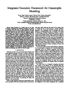
>> n = Node(0) # instantiate a node at address 0 >> n.T # print attribute interactively on next line 100 >> n.T = 200 # set attribute T of n interactively >> n.T 200 >> n.blink_LED(10) >> n.sample_adc() 240 >>
Fig. 1.
Example of an interactive line session, where >> is the prompt.
are implemented on either the host computer or base station. We believe that such a highly interactive execution framework can boost the productivity of WSN developers. A. Illustrative Example Fig. 1 illustrates the interactive programming with an example. Each wireless sensor node is represented as an instance of EcoExec’s Node class in the Python language. It contains node-specific information such as network address, memory layout, etc. Variables and functions on the node are represented as attributes of the Node object in Python on the host, and accessing these attributes will have the effect of remotely manipulating them on the physical node at runtime. Every node instance is declared with the statement “var_name = Node(id)”, where var_name is a variable that represents the newly created node instance, and id is the node’s network address. One can call a function on a sensor node by calling the corresponding method in the node’s representative object in Python. B. Problem Statement The problem is to design a host-assisted runtime system to support interactive execution of commands, by dynamically downloading code to the sensor node if necessary. 1) Requirements and Assumptions: EcoExec is divided into two parts: the host-side shell and the node-side runtime support. A host is a general-purpose computer that provides a command-line interface to the nodes. A host is assumed to be resource-rich with plenty of storage and processing speed. It is also assumed to have been installed with a cross compiler for the nodes and maintains a database that tracks the firmware versions for the nodes.
A node is a wireless sensing system that is connected to the host via a wireless communication interface. Specifically, we target platforms that are highly resource-constrained, so that they can be made ultra compact and low cost. By resourceconstrained, we mean that it has approximately 4KB RAM total for both data and code. If the user issues a command whose code is not in the node’s firmware, then the host sends (“pushes”) the code to the node. In fact, EcoExec goes beyond demand code paging by compiling, linking, and possibly optimizing first before transmission if necessary, and then invokes the function. All these steps should happen transparently to the user. Because the host is several orders of magnitude more powerful than the node and the code is relatively small, all these steps should take a negligible amount of time. It is meant to make resourceconstrained platforms appear much more capable than those that are statically programmed. A requirement for remote programming is that it should use reliable communication. A wireless transmission medium is susceptible to outside interference, and packet loss is inevitable. Due to the fact that reliable transmission is not necessarily supported by the underlying hardware, reliability has to be guaranteed with protocol support. 2) Objectives: As EcoExec targets highly resourceconstrained sensor nodes, our first objective is to minimize the memory footprint of the subsystem that runs on the sensor node. Our second objective is to shorten the response time of commands. The third objective is to minimize radio communication due to sending code. Minimizing energy usage is also considered, but it is not one of the primary objectives in this study. Memory is one of the most expensive parts of integrated components such as microcontroller units (MCUs). SRAM can easily occupy over half of the chip, and leakage becomes a major problem as the feature size decreases. Flash memory may take less area but is by no means free. Although MCUs with 128 KB of integrated flash are available, their chip area is significantly larger and can cost an order of magnitude more than those with less than a dozen kilobytes of flash. Our objective is to minimize the amount of both data and program memory on the node as required by both the runtime system and the application code. We assume most functions for sensing and local processing to be “reasonably sized,” where the working set of the program can fit within the physical memory of the MCU, so that thrashing will not be a problem in practice. The response time here refers to the round-trip time from when the user issues the command on the host to the time the host displays the result sent by the node after it has executed the command. In this study, we assume homogeneous code images on nodes is reachable within a single hop. We assume the host to be a modern personal computer with gigabytes of RAM and can compile code for MCUs with a negligible amount of delay. The potential bottleneck is in either the radio frequency (RF) interface or the MCU. The latency objective can therefore be paraphrased in terms of minimizing the
overhead of the runtime support and minimizing the amount of RF communication due to EcoExec. The third objective is to minimize the amount of RF communication due to transferring code to the node, by choosing a good code replacement policy. Similar to virtual memory, EcoExec needs to dynamically bring in new code from the host to the node from time to time, by replacing some resident code if necessary. C. Outline of Paper The rest of this paper is organized as follows. Section II discusses related works on remote reprogramming. Section III gives an overview of EcoExec. We divide the solution into node side (Section IV) and host side (Section V). Section VI presents experimental results, and Section VII concludes this paper with directions for future work. II. R ELATED W ORK A. Dynamic Reprogramming and Linking Run-time systems for wireless sensor platforms were initially concerned primarily with providing a good abstraction while minimizing overhead [1], [2]. Soon, researchers realized the importance of in-field reprogramming over wireless links and proposed remote firmware update schemes for single hop [3] and multi-hop [4]–[6] topologies. However, full image replacement may be wasteful in terms of transmission and update costs, and researchers propose partial update techniques that can be divided into incremental transmission and linking. Transmission cost can be reduced by sending only the difference computed by diff [7], [8], block-level difference [9], or Rsync [10]. Once the difference is received, the firmware is patched [11]. As an alternative to program image replacement, the runtime system may support loadable modules whose references are resolved either at compile time [12] or when the module is loaded [13]–[15] by a memory relocation mechanism. However, these systems may be dynamic but they are not interactive. B. Interactive Programming An interactive system is one that prompts the user for commands at run time and reports results back to the user instantly if possible. It enables users to test out the behavior of the system incrementally by invoking various functions with parameter values of their choice and confirm their understanding. This represents a much more efficient alternative to the traditional edit-compile-link-program-reset-run cycle, which is not very forgiving if the user makes just one mistake and has no way of getting control back without reset. Interactive systems can also be scripted as a higher-level way of programming. For these reasons, several interactive programming systems have been proposed for wireless sensor platforms. SensorWare [16] allows users to program the nodes using the Tcl [17] scripting language, whose syntax resembles that of many command line shells. However, even after subsetting, the resulting Tcl interpreter still requires a 32-bit MCU and several hundred
TABLE I C OMPARISON OF DYNAMIC R EPROGRAMMING AND L INKING TECHNIQUES . Work Hill [1] Bhatti [2] Stathopoulos [4] Hui [6] Reijers [7] Koshy [8] Jeong [9] Dunkels [12], [13] Cha [14] Han [15] EcoExec
Sensor platform ATMEL 90LS8535 MANTIS nymph Mica2 Mica2 EYES Mica2 Mica2 ESB platform H-mote Mica2 Eco
Data size 226B 500B 700B 84B 2KB 4KB 4KB > 230B > 724B 1KB 256B
Program size 3.4KB 14KB 4.5KB 128KB 60KB 128KB 128KB 3.8KB > 20KB 20KB 4KB
Runtime support TinyOS MANTIS OS moap deluge diff-based edit script Remote linking producing deltas Rsync algorithm diff Contiki RETOS SOS Script-assisted dynamic loading
Fig. 3.
Fig. 2.
System overview.
kilobytes of memory to run. LiteOS [18] presents a Unix-like abstraction for WSN by providing a command line interface to sensor nodes, which are mapped to files in directories that correspond to their network hierarchies. LiteOS shell can also support interactive commands and debugging features, but it requires the entire modified application program to be relinked and replaced. BerthaOS running on the PushPin wireless sensor nodes can handle Pfrags [19], which are fixed-sized (2KB) program fragments that can be dynamically loaded and executed to achieve interactivity. However, the host-side interface appears more limited. The smallest footprint of all is Tapper [20], which supports a customized, synthesized parser for the chosen set of commands and can run with 1KB of RAM. However, its command set is fixed and would require full image replacement to update. The approach taken by EcoExec is two folds. First, we generalize the dynamic loading of program fragments (as in BerthaOS) by involving a compiler in the loop on demand. Second, we extend the host-assisted execution (as in Tapper and LiteOS) by packaging the concepts in a dynamic objectoriented language such as Python, which can be used either interactively or in batch mode. Sensor nodes are accessed as method calls to objects, which abstract away not only communication and networking details but also compiler, linker, and loader invocations when the required binary is not resident in the firmware. This scheme enables ultra compact, resourceconstrained nodes to be equally capable to those systems with several orders of magnitude more resources. III. S YSTEM OVERVIEW Fig. 2 shows an overview of EcoExec. It is composed of two subsystems: the host and the wireless sensor nodes. Each host computer is connected to a base station and issues commands to wireless sensor nodes. The Host subsystem provides functionality for management and control of the wireless sensor network. EcoExec provides a command line interface
EcoExec execution flow.
(CLI) named ExShell for users to administer the whole system. Programmers can also group multiple commands into a script file to be executed in batch. The base station relays messages between the host PC and the nodes. The Node subsystem executes a main loop while listening to incoming packets for potential commands. Commands include not only those issued by the users but also reprogramming ones automatically inserted by EcoExec in order to properly load and execute the desired code. Communication between the Host and the Node subsystems is done through the base station. We assume that the communication protocol is reliable, and this can be achieved by having the sender wait for an acknowledgment or retransmit otherwise. The execution flow of EcoExec is depicted in Fig. 3. From initialization of the system to receiving of node responses for a command, the sequence of operations is as follows. 1) Initialization (host and node): The host queries the database to load information about each node’s program structure, network configuration, and memory layout. Each node boots up. 2) Command Input (host): The user types a command into ExShell on the host, or the interpreter executes a step in the batch file. 3) Command Processing (host): ExShell checks if the invoked function is resident in the target node. If so, then the shell looks up the function definition and location and sends a command to the node. Otherwise, the shell invokes the incremental linker on the new function to produce a new binary image that is diff’ed with the previous image. It then sends both the diff script followed by a command to invoke the corresponding actions on the node. 4) Message Issuing (host): The host transmits the message to the base station via Ethernet. The base station translates each packet into RF packets and transmits them to the target node. The host retransmits if it does not receive an acknowledgment from the node. 5) Message Decoding (node): The Node subsystem decodes RF packets and executes the corresponding actions, if the packet is not a duplicate.
Fig. 4.
RF packet format.
6) Code Installation (node): If the message indicates a store operation, then the binary data in the RF packet is written directly into the designated memory location. 7) Function Execution (node): If the message indicates function execution, then the Node subsystem invokes the desired function as an active message. The function’s return value, if any, is sent to the host as part of the reply message payload. 8) Result Display (host, optional step): If the action above has a return value, then the Host subsystem parses the payload of the RF packet and shows the result in the user interface (ExShell). IV. N ODE S UBSYSTEM We demonstrate the feasibility of EcoExec on a wireless sensor platform called Eco, which contains an integrated MCU+RF chip and a triaxial accelerometer. The rest of this paper assumes the 8051 instruction set architecture (ISA), although the concept of EcoExec can also be implemented on many other networked embedded systems platforms of different ISAs. The Node subsystem sits on top of a layer of device drivers. Among them, the drivers for the serial peripheral interface (SPI), EEPROM, and RF transceiver are the essential drivers that must be included before deployment. Drivers for other devices such as UART, analog-to-digital converter (ADC), or SD card interface are not installed until they are needed. Overall, the Node subsystem supports remote function execution and remote reprogramming in terms of two main components: store and execute. The execute component calls functions as commanded, while the store component stores received data at the designated memory location. Each component consists of a set of handler functions. For example, a get handler returns memory content and can be remotely invoked by the Host subsystem for dumping memory content. A. Message Formats Due to the constraint imposed by our chosen RF hardware, each message is encapsulated in the 23-byte payload of an RF packet that starts with a 1-byte preamble and a 3-byte address field, followed by the packet payload (message) and a 2-byte CRC field, as shown in Fig. 4. The two categories of messages are ordinary messages and executable messages. 1) Ordinary Messages: An ordinary message is handled by a designated handler with the whole message as its input. When an ordinary message is received, the Node subsystem parses the message and acts accordingly. EcoExec uses ordinary messages to update the program memory or install new functions by copying binaries to a specific memory location.
Fig. 5.
Example of an executable message to call function foo(10).
2) Executable Messages: An executable message is an extension of an active message [21], which contains the pointer to the handling function along with the parameter values. It is a fast way to dispatch packets, because no separate parsing is necessary before deciding how to handle them, and it is much lower overhead than using a switch/case statement to decide which function to invoke. An executable message does not just simply contain the function pointer, but it actually contains executable instructions to set up the call before the target function is invoked. EcoExec adopts executable messages to enable efficient over-the-air execution of functions on the sensor node. The function argument values have to be encoded into the message, and the function return value has to be returned to the host. Since the Host subsystem maintains detailed information of the application program running on each node, the host can generate a sequence of assembly instructions for argument value passing, desired function invocation, and return value handling based on this information. This sequence of instructions is encoded into a message and sent to the target node in an RF packet. Upon receiving the packet, the Node subsystem examines the message within and executes it if it is in the executable message format. B. Function Invocation Fig. 5 shows an example of how an executable message causes function foo(10) to be called in the Node subsystem. When an RF packet is received and read into the RF buffer in the program memory, the first byte of the message is examined. If it is 0, then it indicates that the message is an executable
TABLE II RULES OF ARGUMENT PASSING USING COMPILER . Arg. No. 1 2 3
char or 1-byte ptr R7 R5 R3
int or 2-byte ptr R6, R7 R4, R5 R2, R3
REGISTERS FOR
long, float R4–R7 R4–R7
K EIL C51
generic pointer R1–R3 R1–R3 R1–R3
TABLE III RULES OF FUNCTION RETURN VALUES USING REGISTERS FOR K EIL C51 COMPILER . Return Type bit char, 1-byte ptr int, 2-byte ptr long float generic ptr
Register CY R7 R6/R7 R4 – R7 R4 – R7 R1 – R3
Description Carry flag
void return_value_handler(int len, char *addr, char *data);
The return value handler copies the return value into the RF buffer (labeled RF_BUFFER in Fig. 5) in the program memory. The RF buffer is formatted into a reply message and sent to the host. void store_handler(int len, char *addr, char *data);
The store handler copies the RF payload from the hardware buffer to the program memory as specified in the store message. By default, the code resides in RAM and will be lost upon reboot. However, the user can set the EEPROM bit in the store message to cause a copy of the code to be written to the (off-chip) EEPROM. void swap_handler(int len, char *ram_addr, char *rom_addr);
MSB in R6, LSB in R7 MSB in R4, LSB in R7 32-bit IEEE format Memory type in R3
message, as shown in step 1 in Fig. 5. An executable message contains the reference to the desired function to be invoked. As shown in the shaded part of program memory in Fig. 5, the RF buffer where the received executable message is stored can be seen as a memory space that contains a function while the sequence of assembly instructions to be executed serves as the content of the function. When the RF buffer is called, the program counter is moved to the start of the buffer to carry out the instructions stored within, which is step 2 in Fig. 5. These instructions mainly involve MOV and LCALL instructions, used to copy argument values into their corresponding memory locations and to call a function or a return value handler. These MOV instructions are generated by the Host subsystem based on the parameter passing rules defined by Keil Cx51 (using registers to pass parameters) and the memory address of function local variables. The Keil Cx51 compiler allows up to three input arguments to be passed in CPU registers with a fixed rule shown in Table II. The remaining input arguments are passed with function local variables. Step 3 in Fig. 5 uses the assembly instruction “MOV R7, #10” to set 10 as the parameter to the function foo. LCALL instructions are generated by the Host subsystem according to the memory address of the function and the return value handler. These instructions are used to call the desired function and return value to Host subsystem. Similar to function parameters, Keil C compiler follows a rule when generating instructions for handling the return value as shown in Table III. As the memory content is stored in the RF buffer, the original RET instruction at the end of the sequence of instructions may be overwritten. Thus, the handler returns directly to the main execution loop by popping out a return address on the stack as shown in steps 5 and 6 in Fig. 5. C. Subsystem Handlers This subsection details the essential handler functions that comprise the execute and store components of the Node subsystem.
The swap handler is responsible for swapping a segment (of code) from the EEPROM to the program RAM. In addition, the handler can save the content of the program memory space (that is about to be overwritten) to a designated location in the external EEPROM. void get_handler(int len, char *address);
A get handler copies the memory content from specified address of the program memory or the data memory into the RF buffer (labeled RF_BUFFER in Fig. 5) to be transmitted back to the host in a reply message. void set_handler(int len, char *address, char *data);
A set handler copies the payload content to the designated memory address, pops out the return address at the top of the stack, and returns directly to the main execution loop. V. H OST S UBSYSTEM The Host subsystem is divided into three parts: scripting engine, code generator, and communication. The scripting engine provides the interactive programming interface to the wireless sensor nodes. It includes a general-purpose shell named ExShell written in Python and enables users to access all features in Python. It also wraps node references and API in the form of dynamic objects in Python to facilitate application development. The object wrapping also enables the code paging mechanism to download code to the node if it is not resident. The code may be compiled and linked if necessary. Then, communication with the sensor node is done by sending the packet via Ethernet to the base station, which then forwards the packet to the target node. A. Scripting Interface The scripting engine handles the execution of every input command. Each command is a Python statement that is verified by ExShell before execution. Commands can be further defined collectively in a script file for batch execution. Commands can be roughly categorized into local host commands and remote node commands. Syntactically there is no difference. Users access the nodes with object syntax, and the object wrapper automatically handles them, by communicating and reprogramming the sensor node if necessary. Fig. 1 shows an example of a command script. Line 1: n = Node(addr) This calls the constructor for Node class with the node address and assigns the object reference to variable n.
Line 2: n.T Python calls n.__getattr__(name="T"). This accesses the attribute named T in the node instance named n. The scripting engine handles it by sending a message to the node referenced by n to look up the value, receiving the value, formatting and displaying it when in interactive mode. Line 4: n.T = 200 Python calls n.__setattr__(name="T", value=200). This assigns the value 200 to the attribute named T in the node instance n. The scripting engine handles it by sending a message to the node referenced by n to set the T attribute to the value 200. Line 7: n.blink_LED(10) This calls the function named blink_LED on the node n with parameter value of 10 (time units). If the function does not already exist on the node, then the code generator part generates the code, which is packaged and transmitted to the node to be reprogrammed, and the node invokes the newly installed function. Line 8: n.sample_adc() The host sends a message to the node n to call the sample_adc() function, and the node replies with the ADC value. The host receives the data, interprets it as an int (R-value), and renders it as a decimal string in interactive mode on line 9. If the value is assigned to a variable or in batch mode, then it does not render the string. This example demonstrates not only the highly interactive access but also how EcoExec abstracts away all of the complexity associated with network programming. The implementation also represents a good match with Python as a dynamic language. Each object carries a symbol table, and methods (object-local functions) and attributes (fields, or object-local variables) can be added and deleted at runtime. By implementing the __getattr__ and __setattr__ methods, one can have full control over exactly how each attribute should be accessed, including caching and raising exceptions if necessary. It also blends in naturally with the operator syntax of Python expressions. This means node objects can be used in ways entirely indistinguishable from ordinary Python objects. It is also worth noting that the code on the node does not need to perform string formatting. For example, on line 9 in the example above, the interpreter prints the string returned by the int object 240’s __repr__ method. This way, the node does not need to perform any string formatting, while the value is readily usable by other Python code without parsing. B. Code Generator The code generator is invoked on demand when a node is about to execute a piece of code that is not resident in its program memory. We use an existing compiler to generate relocatable code and a linker to generate a new binary image according to our specified memory layout. The Host subsystem then transmits the diff’ed patches to the nodes. We describe two cases: adding new code and modifying existing code. The first case covers the programs being compiled for the first time.
1) Newly Added Code: The first case involves adding the code, data, and constants of new functions to an existing program. All existing segments, including code, data, constants, global variables, and library routines, are kept at their original addresses in order to avoid changing existing code. After fixing those locations, the linker then automatically allocates new addresses for new segments in the new function. We use the first-fit policy to achieve the code replacement if the remaining memory space is not enough for the newly added code. 2) Modifying Existing Code: Modifications include relocating a function or overwriting its content. If a callee function is moved, then all callers must also be updated with the new callee address, unless a jump table is used. Furthermore, the program structure has to be carefully managed for reprogramming to take place during runtime without rebooting. Modifications made to a function may affect the sizes of its segments. As segments are tightly situated with no gap in between segments, segments expanded due to the function update would cause later segments to be relocated. Consequently, references to the relocated segment need to be patched. Reclamation of the memory space is passive as the memory map stored on the host tracks free regions. Upon the generation of a new program image, binaries of the new functions are extracted while pre-existing segments that are updated are diff’ed with the original to generate the patching binaries. These patches are then wrapped into store messages for installation or update on the target node. C. Communication A base station is attached to the host computer and is considered part of the host, even though it contains its own MCU and can run independently. Each host PC has a base station connected to it by TCP/IP over Fast Ethernet. The base station has an Ethernet adapter and a 2.4 GHz RF transceiver for RF communication. Both the Ethernet interface and the RF interface continuously listen for incoming Ethernet and RF packets separately. VI. E VALUATION This section first describes the experimental setup used to evaluate the performance of EcoExec. We present the experimental results for a series of application updates in terms of three metrics: upload size, execution latency, and code size. To identify the bottleneck, we also analyze the performance in each stage of the application update procedure. A. Experimental Setup This section gives a brief description of the hardware used in the experiments and different applications remotely programmed into the sensor node. 1) Wireless Sensor Node: We implemented the Node subsystem of EcoExec on the ultra compact wireless sensor node named Eco, as shown in Fig. 6. It is small, compact, and highly resource-constrained. At the core of Eco is the Nordic nRF24E1, which contains an integrated nRF2401Acompatible transceiver in the 2.4GHz ISM band and an 8051compatible MCU core, plus digital and analog I/O interfaces.
(a) Eco on a fingertip. Fig. 6.
(b) Eco front view. Eco: 6(a) and 6(b).
The nRF24E1 also contains 4K bytes of RAM shared between program and data. The firmware is stored in a separate electrically erasable programmable read-only memory (EEPROM) component that is 4K bytes in size. 2) Base Station: The base station hardware used in the experiment is built by connecting a Nordic nRF2401 2.4GHz RF transceiver module to a Freescale DEMO9S12NE64 evaluation board over its 40-pin expansion connector. It contains a 16-bit HCS12 MCU with 64K bytes of flash and 8K bytes of RAM, plus a Fast Ethernet (10/100 Mbps) MAC/PHY transceiver that serves as the uplink to the host. 3) Host computer: The host computer is a general purpose PC with a Fast Ethernet adapter. It is equipped with Intel Core2Duo CPU E7200, 2.53GHz clock frequency, and 3 GB of RAM (2.96 GB usable). The PC runs the Keil C development toolkit v8.16, Linker LX51 v4.34, and Python 2.6 on Windows XP. B. Applications We have created three applications: Calculator, ADCSampling, and a Snake game, with sequences of application updates to demonstrate EcoExec’s interactive remote function execution and reprogramming mechanisms and to evaluate their performance. The target sensor node is deployed with only the Node subsystem running and no other application or firmware installed. At this time, only the essential drivers are installed, specifically drivers for SPI access, EEPROM read/write, and RF component manipulation. The command script is then input into the Host subsystem to carry out the eight steps of the experiment: 1) Calculator Installation: The first application, Calculator, is installed on-demand. The Calculator application is composed of a main CAL() function and several other functions. Functions include PLUS() for summing up two arguments, MINUS() for subtracting the second argument from the first, MUL() for multiplying the two arguments, DIV() for division of two arguments, and stepT() that takes only one input argument and returns the sum of the input and global variable T. Functions are defined in the function source file. They are compiled and linked incrementally based on the need of the Calculator application. The math library is also incrementally linked to generate a new binary image. 2) Modifying Calculator Functions: Next, we modify the source files for PLUS() and MINUS() functions, which are located adjacently in the original code image. Both functions expanded
in size. The code for the new PLUS() function cannot fit in the memory region in the original image, and thus it must be moved to a larger available memory space. On the other hand, the new MINUS() function can fit in the original space taken up by PLUS() and MINUS(), and thus the new code is written into this old region. 3) Major Modification to Calculator Application: The Calculator application is furthered updated by removing cases that involve calls to the math library in the CAL() function, as well as exchanging content between cases. As a consequence, the new CAL() function behaves almost entirely differently from the original. Moreover, the composition of the library segment is affected as math library functions are no longer needed. Binaries of the library segment are also updated to accommodate this change. 4) Installing ADC-Sampling: The code for ADC-Sampling did not come pre-installed, and ExShell determines this condition by checking its local database. The Host subsystem incrementally links the object file with the previous application that exists. Because the memory cannot contain both applications, the linker overwrites the original application code with that of Calculator. 5) Adding Filter Functions: The next command invokes three additional functions that act as filters for the converted ADC values for each of the three axes. The sampling function is also modified to include these filters. The Host subsystem generates the newly added and modified code and loads it into the node. 6) Minor Modification to the Filter Functions: We make a minor modification to the filter functions by updating the controlled return values. Each function may return one of the two controlled values based on the comparison between the actual value and the threshold. 7) Major Modification to the Filter Functions: We modify the filter functions for X-axis and Y-axis by applying more complex processing. In the original image, the code for the X-axis filter is ordered immediately before that for the Y-axis filter. Due to the size increase, one of the functions is relocated elsewhere, while the other reuses the original space that was taken by both old functions. 8) Install Snake_game: The code for Snake_game is to read the triaxial acceleration values as sampled by the ADC. The data is then used to control the direction of an animated snake on the host side. Since some of the driver code such as RF and ADC has been installed before, we need to upload only the diff code, which is smaller than the entire code. Details of the update phases are shown in Table IV. C. Upload Size We evaluate the performance of remote function execution and remote reprogramming for each phase of the experiment. Fig. 7 shows the total code size (excluding EcoExec), modified code size, and the diff size. Note that the actual diff script is slightly larger than the diff data, since it must contain metadata for the patching command (action, starting address, segment length). In the first step, when Calculator function is uploaded
TABLE IV C ONSISTING FUNCTIONS AND UPLOAD SIZE FOR Step 1
Update phase Install Calculator
2 3 4
Modify PLUS,MINUS Major modify Calc. Install ADC-Sampling
5
Add filters
6
Minor modify filters
7
Major modify filters
8
Install Snake_game
Consisting functions CAL,MINUS,PLUS,DIV,MUL,LOG,RAND, SQRT,LIB_CODE,PUTS,SERIAL_WRITE CAL,MINUS,PLUS CAL,MINUS,PLUS,LIB_CODE ADC_READ,ADC_INIT, MASS_READ_ADC,MASS_INIT_ADC MASS_X_FILTER,MASS_Y_FILTER, MASS_Z_FILTER MASS_X_FILTER,MASS_Y_FILTER, MASS_Z_FILTER MASS_READ_ADC,MASS_X_FILTER, MASS_Y_FILTER,MASS_Z_FILTER SNAKE_READ_XYZ, MDELAY
Diff/Mod./App. size(B) 1801/1801/1801 21/173/1801 306/1193/1801 190/190/190 183/183/288 24/63/288 73/141/294 291/291/1131
2,000
App. Size Mod. Size Diff Size
Bytes
1,500 1,000 500 0 Step 1
Step 2
Step 3
Step 4
Step 5
TABLE V C OMPARISON OF M EMORY FOOTPRINT ( BYTES )
EACH UPDATE PHASE
Step 6
Step 7
Step 8
Fig. 7. Total application size, modified size, and diff’d size for the eight steps in the code update
for the first time, there is no previous version to diff with. Therefore, the diff size is equal to the size of the application. In the second step, after Calculator has been installed, the PLUS and MINUS functions are modified. In this case, the entire PLUS function is moved and transmitted in its entirety, whereas the MINUS function stays and is patched. The CAL function itself is affected only as a caller of the moved function PLUS (therefore a 1-byte diff). In the third step, deletion of code and most math library did not require any action on the node side. The diff code consists of mainly rearrangement of cases within CAL function (104-byte diff) and addition of other library code (named ?C?LIB_CODE with 198-byte diff). The fourth and fifth steps are new installations, and therefore the diff sizes are the same as the original. In the sixth step, the three filters underwent minor modifications. Four int-type constants are modified in each filter function, requiring 8 bytes to be patched. In the seventh step, two of the filter functions X_FILTER and Y_FILTER are further reprogrammed with more complex calculations. Similar to phase 2, the two functions expand; but only the X_FILTER function is relocated while the Y_FILTER function remains at the starting location that had extra space due to the relocation of X_FILTER. The reference to X_FILTER from inside MASS_READ_ADC has to be updated as well. Finally, the snake game contains new code, although the ADC functions can be reused. Some code that was marked reclaimable space did not get reclaimed, and they were marked non-free again when used by the new application. This does not require another upload. D. Memory Footprint EcoExec consumes about 430 bytes of program memory and 30 bytes of data memory, excluding the essential device drivers. With the drivers, the system takes up about 1808
OS or Runtime Prog. mem. Data mem.
Maté 39746 3196
SOS core 20464 1163
TinyOS+ Deluge 21132 597
LiteOS 30822 1633
Mantis OS ≈ 14000 ≤ 500
EcoExec ≈ 1808 ≤ 60
TABLE VI L ATENCY OF REMOTE FUNCTION EXECUTION Command No filters sampling Add filters Modify filters Complex filters
Samples 500 50 50 50
Duration (s) 24 2.6 2.3 3.1
Samples/s 21 19 21 16
Sample duration (s) 0.048 0.052 0.046 0.062
bytes of program memory and 60 bytes of data memory. Its memory footprint is significantly smaller than that of other works that offer remote reprogramming support. Table V show a comparison of memory footprints. E. Command Latency Latency is evaluated in the two scenarios: remote function execution and remote reprogramming. We evaluate the time needed for a request to receive its response, namely the duration between entering a command and receiving a result. 1) Remote Function Execution: During each phase of the ADC-Sampling application updates, a number of samplings are requested by the Host subsystem. Table VI shows the total execution time for sampling under different application conditions. On average, the system retrieves 20 samples per second (sps), or a 50 ms latency, which is barely noticeable to the user. Sampling with simple or no filters results in 20 sps, whereas adding complex filters results in 16 sps. 2) Remote Reprogramming: We measure the latency from a command being issued to the application being installed and executed. The latency of each update phase is shown in Table VII. Fig. 8 shows the ratios of incremental linking and uploading to the total duration. The upload duration is proportional to the upload size. The incremental linking time for ADC-Sampling application installation is higher than that of other phases due to more complicated memory layout adjustments to install a new application over the original application while keeping shared functions at their starting locations. Besides, the host PC we use may also affect the time of incremental linking. On average, it takes about 2.5 ms to upload one byte and write it into program memory; an additional 2.5 ms is needed to write the byte into offchip program memory (EEPROM). The incremental linking process takes about 400 ms to 800 ms on average. Installing an application that consumes 1800 bytes of program memory will need about 5.5 seconds (worst case), while an average binary takes less than 2 seconds. Such a response time is acceptable as application updates happen only once in a while, and interactive invocation does not always require reprogramming most of the time. Furthermore, next-generation sensor platform [22] will feature twice the data bandwidth (2 Mbps) and hardware support for reliable communication. It is expected to cut the latency even further.
TABLE VII L ATENCY OF REMOTE REPROGRAMMING (N OT WRITING Update phase Install Calculator Cal. minor modification Cal. major modification Install ADC-Sampling Add filters Modify filters Complex filters Snake game
Duration (sec) 5.51 1.45 2.40 4.25 1.81 1.25 1.57 1.78
INTO
Incremental linking (sec) 0.40 0.78 0.76 3.19 0.75 0.39 0.77 0.76
EEPROM). Upload (sec) 4.36 0.10 1.07 0.51 0.51 0.30 0.25 1.02
Install Calculator Cal. major modification Install ADC-Sampling Add filters
R EFERENCES
Modify filters Complex Filters 0
1.5
3.0
4.5
6.0
Duration(sec)
Incremental linking
Upload
Others
Ratios of incremental linking and upload to the total duration.
F. Power Consumption Table VIII shows the power consumption on Eco node in different modes. The power consumption of program memory write is 8.88mW, which is less than 15.54 mW when doing EEPROM write. VII. C ONCLUSIONS AND F UTURE W ORK This paper has presented a framework for wireless sensor node interaction called EcoExec. The framework offers assistance to programmers for remote function execution and remote reprogramming of sensor node programs. EcoExec extends the limited computation capabilities of sensor nodes to the feature-rich functionalities of Python by providing a Python-abstraction for WSN. Experimental results show that the framework is memory-efficient and yields low latency in sensor node service requests. Future work includes improving code replacement policy and transmission overhead. Currently memory is allocated but not released unless manually marked so, but it should be automated with lifetime analysis. Data relocation also needs to be taken into consideration. When new functions cause existing functions to be evicted, we currently use the first-fit policy, but a better policy may be based on how frequently a piece of code is executed or on temporal locality (e.g., least-recently used). In addition, we are working on porting more applications to EcoExec. To improve power efficiency, we could include some power management mechanisms or incorporate some energy-efficient MAC protocols, although one may need to TABLE VIII P OWER C ONSUMPTION ON E CO NODE ( AT 2.2V) Power mode Power (mW)
RF Tx (0dBm) 32.93
VIII. ACKNOWLEDGMENTS This work was sponsored by the National Science Foundation CNS-0448668, CNS-0721926, CBET-0933694, the National Science Council (Taiwan) NSC 98-2200-E-007-006, and Ministry of Economy (Taiwan) 98-EC-17-A-07-S1-001.
Cal. minor modification
Fig. 8.
make trade-offs between latency or memory footprint. Another direction for future work includes more optimization based on run-time constants and multi-hop topologies. These are expected to make the extremely resource-constrained, low-cost WSN platforms useful for many applications. The source code to EcoExec is available on our website [23].
RF Rx 45.88
EEPROM write 15.54
Program mem. write 8.03
Idle 7.66
[1] J. Hill, et al., “System architecture directions for networked sensors,” in ASPLOS-IX, 2000, pp. 93–104. [2] S. Bhatti, et al., “MANTIS OS: an embedded multithreaded operating system for wireless micro sensor platforms,” Mob. Netw. Appl., vol. 10, pp. 563–579, 2005. [3] Crossbow Technology, Inc, “Mote in-network programming user reference version 20030315,” http://www.tinyos.net/tinyos-1.x/doc/Xnp.pdf, 2003. [4] T. Stathopoulos, J. Heidemann, and D. Estrin, “A remote code update mechanism for wireless sensor networks,” UCLA, Tech. Rep., 2003. [5] S. S. Kulkarni and L. Wang, “Mnp: Multihop network reprogramming service for sensor networks,” in ICDCS, 2005, pp. 7–16. [6] J. W. Hui and D. Culler, “The dynamic behavior of a data dissemination protocol for network programming at scale,” in SenSys, 2004, pp. 81–94. [7] N. Reijers and K. Langendoen, “Efficient code distribution in wireless sensor networks,” in WSNA, 2003, pp. 60–67. [8] J. Koshy, “Remote incremental linking for energy-efficient reprogramming of sensor networks,” in EWSN, 2005, pp. 354–365. [9] J. Jeong and D. Culler, “Incremental network programming for wireless sensors,” in SECON, 2004, pp. 25–33. [10] A. Tridgell, “Efficient algorithms for sorting and synchronization,” Ph.D. dissertation, Australian National University, 2000. [11] P. J. Marron, et al., “FlexCup: A flexible and efficient code update mechanism for sensor networks,” in EWSN, 2006, pp. 212–227. [12] A. Dunkels, B. Gronvall, and T. Voigt, “Contiki - a lightweight and flexible operating system for tiny networked sensors,” in LCN, 2004, pp. 455–462. [13] A. Dunkels, et al., “Run-time dynamic linking for reprogramming wireless sensor networks,” in SenSys, 2006, pp. 15–28. [14] H. Cha, et al., “RETOS: resilient, expandable, and threaded operating system for wireless sensor networks,” in IPSN, 2007, pp. 148–157. [15] C.-C. Han, et al., “A dynamic operating system for sensor nodes,” in MobiSys, 2005, pp. 163–176. [16] A. Boulis, C.-C. Han, and M. B. Srivastava, “Design and implementation of a framework for efficient and programmable sensor networks,” in MobiSys, 2003. [17] J. K. Ousterhout, “Tcl: An embeddable command language,” in Proceedings of the USENIX Winter 1990 Technical Conference, 1990. [18] Q. Cao, et al., “The LiteOS operating system: Towards unix-like abstractions for wireless sensor networks,” in IPSN, 2008, pp. 233–244. [19] J. Lifton, et al., “Pushpin computing system overview: A platform for distributed, embedded, ubiquitous sensor networks,” in Pervasive, 2002, pp. 139–151. [20] Q. Xie, J. Liu, and P. H. Chou, “Tapper: A lightweight scripting engine for highly constrained wireless sensor nodes,” in IPSN, 2006. [21] T. V. Eicken, et al., “Active messages: a mechanism for integrated communication and computation,” in ISCA, 1992, pp. 256–266. [22] C.-Y. Chen, et al., “EcoSpire: An application development kit for an ultra-compact wireless sensing system,” in Embedded Systems Letters, 2009. [23] “EcoExec Source Files.” [Online]. Available: http://epl.cs.nthu.edu.tw/EcoKit/download/EcoExec.zip