Jul 3, 2009 - study the m-coverage and n-connectivity problem under border effects. We consider the scenario where the heterogeneous sensor nodes are ...
IEEE TRANSACTIONS ON VEHICULAR TECHNOLOGY, VOL. 58, NO. 3, MARCH 2009
1429
EECCR: An Energy-Efficient m-Coverage and n-Connectivity Routing Algorithm Under Border Effects in Heterogeneous Sensor Networks Yan Jin, Ling Wang, Ju-Yeon Jo, Yoohwan Kim, Member, IEEE, Mei Yang, Member, IEEE, and Yingtao Jiang, Member, IEEE
Abstract—Wireless sensor networks (WSNs) can be used to monitor the interested region using multihop communication. Coverage is a primary metric to evaluate the capacity of monitoring. Connectivity also needs to be guaranteed so that the sink node receives all sensed data for future processing. In this paper, we study the m-coverage and n-connectivity problem under border effects. We consider the scenario where the heterogeneous sensor nodes are randomly distributed in a circular region. We first exactly derive the network m-coverage ratio that is provided by N sensor nodes by the mathematical formulas. Then, the lower bound of the network n-connectivity probability is also derived. Since sensor nodes are equipped with energy-limited batteries, energy conservation in such networks is of paramount importance to prolong the lifetime of the network. Accordingly, we propose a location-independent, energy-efficient routing algorithm EECCR, which simultaneously preserves the network m-coverage ratio and the sensor n-connectivity probability. Extensive simulation results are provided to demonstrate that our algorithm is correct and effective. Index Terms—Border effects, connectivity, coverage, energy efficient, routing, wireless sensor networks (WSNs).
I. I NTRODUCTION
W
ITH THE development of very-large-scale integration, micro-electro-mechanism system, and wireless networking technology, wireless sensor networks (WSNs) have attracted a lot of attention in recent years [1]. A WSN is composed of numerous tiny sensor nodes. These nodes have processing and communication capacities, which enable the collection of surrounding information and then the transmission of the report data to a sink node/base station. The sink node agManuscript received March 12, 2007; revised November 14, 2007, April 17, 2008, and May 5, 2008. First published May 28, 2008; current version published March 17, 2009. This work was supported by the National Science Foundation of China under Grant 60706004 and Grant 60876018 awarded to Dr. L. Wang. The review of this paper was coordinated by Dr. J. Misic. Y. Jin is with the School of Computer Science, Harbin Institute of Technology, Harbin 150001, China, and also with the Department of Electrical and Computer Engineering, University of Nevada, Las Vegas, NV 89154 USA. L. Wang is with the School of Computer Science, Harbin Institute of Technology, Harbin 150001, China. J.-Y. Jo is with the School of Informatics, University of Nevada, Las Vegas, NV 89154 USA. Y. Kim is with the School of Computer Science, University of Nevada, Las Vegas, NV 89154 USA. M. Yang and Y. Jiang are with the Department of Electrical and Computer Engineering, University of Nevada, Las Vegas, NV 89154 USA. Color versions of one or more of the figures in this paper are available online at http://ieeexplore.ieee.org. Digital Object Identifier 10.1109/TVT.2008.926216
gregates and analyzes the report data received and then decides whether there is an unusual or exceptional event occurrence in the deployed region. There are many practical applications of WSNs, such as environmental surveillance, battlefield tracking, and target detection [2]. Unfortunately, some inevitable practical factors hinder the WSNs to be used ubiquitously. For example, the battery power carried by a sensor node is limited, which prevents the node from executing complex instructions or algorithms. In many applications, the desired lifetime of a sensor network is on the order of a few years. It may be infeasible or undesirable to recharge batteries in sensor nodes once a WSN is deployed. Hence, energy efficiency is a paramount design consideration for all WSNs. By now, three main approaches have been applied to reduce energy consumption. The first is to design the energy-efficient hardware device for the sensor node [3], [4]. The second is to design the energy-efficient protocols throughout all stack layers [5]. For example, in the media access control layer, power consumption can be reduced by decreasing the wake-up time of a transmitter or by employing smart scheduling of slots to avoid signal collision and data retransmission [6]. In the network layer, a clustering routing algorithm, called the low-energy adaptive clustering hierarchy, utilizes a randomized rotation of a local cluster head (CH) to evenly distribute the energy load among nodes in the network [7]. It also uses localized coordination to enable scalability and robustness for dynamic networks and incorporates data fusion into the routing protocols to achieve energy conservation. Younis and Fahmy [8] presented a hybrid energy-efficient distributed clustering algorithm that periodically selects CHs based on the node’s residual energy and a secondary parameter, such as the node proximity to its neighbors or the node degree. Bandyopadhyay and Coyle [9] proposed a distributed clustering algorithm where the communication between the node and its CH is organized in a multihop manner. Using the results of stochastic geometry, the authors formulated a network energy dissipation function and derived probability p of becoming a CH that minimizes energy dissipation. The value of H, i.e., the maximal number of hops from a node to its CH, is also calculated in [9]. Furthermore, Jin et al. [10] proposed an energy-efficient multilevel clustering algorithm EEMC and asymptotically derived the optimal number of levels to minimize the network energy consumption. The third is to schedule the redundant sensor nodes into sleep
0018-9545/$25.00 © 2008 IEEE
Authorized licensed use limited to: University of Nevada Las Vegas. Downloaded on July 3, 2009 at 17:49 from IEEE Xplore. Restrictions apply.
1430
IEEE TRANSACTIONS ON VEHICULAR TECHNOLOGY, VOL. 58, NO. 3, MARCH 2009
status while preserving some network properties (e.g., network connectivity [11], [12], network coverage [13]–[15], or both [16]–[20]). Among these three energy-efficient approaches, the last one is the most effective because it can decrease the number of active nodes, thus avoiding the channel collision, reducing the network energy consumption, and prolonging the network lifetime substantially. Compared with the above literature, in this paper, we study m-coverage and n-connectivity problems under border effects in heterogeneous sensor networks (m ≥ 1, n ≥ 1). Then, by integrating the routing and scheduling issues, we propose an energy-efficient routing algorithm, i.e., EECCR, to simultaneously achieve full/partial m-coverage and n-connectivity. The rest of this paper is organized as follows. Section II surveys the related work. In Section III, notations, assumptions, and definitions are presented. Given N sensor nodes, Section IV analyzes the m-coverage ratio and the n-connectivity probability. Some useful theorems/corollaries are also provided in this section. The EECCR, which is an energy-efficient m-coverage and n-connectivity routing algorithm, is proposed in Section V. In Section VI, the extensive simulation results are shown to validate our analysis and to compare our algorithm with others. Section VII concludes this paper and gives future directions. II. R ELATED W ORK Coverage is an important metric to measure the quality of service of the network. This problem is centered on a fundamental question, “How well do the sensor nodes monitor the physical space?” which has been extensively addressed in the literature. Most existing works on the area coverage problem aim to cover the entire region of interest [21]. Ye et al. [13] developed probing environment and adaptive sleeping (PEAS), i.e., a probing mechanism that is designed to conserve energy. The PEAS does not require any node to maintain knowledge of the states of its neighbors, and it randomly distributes node wake-ups over time. When a sleeping node wakes up, it detects whether any active node is present within a certain probing range by broadcasting a probing message and waiting for a reply. If no reply is received within a time period, it starts working until it fails or depletes all its energy. In this solution, the application-specified probing range indirectly determines the degree of coverage. However, this probing-based mechanism has no guarantee of adequate network coverage. Tian and Georganas [14] developed a sponsored area algorithm, which aims at providing full coverage by its offduty eligibility rules. A node can turn itself off as long as its active neighbors can cover all of its sensing area. In addition, a back-off-based, self-scheduling scheme was presented to avoid generating possible blind points of coverage when several neighboring nodes try to fall asleep simultaneously. This rule underestimates the area that is already covered because the node only considers the sponsored area provided by the nodes that are located in its sensing area; therefore, much extra energy is consumed. In one of the earliest works that are related to the network coverage, Slijepcevic and Potkonjak [15] introduced a central-
ized algorithm that selects mutually exclusive sets of nodes due to the NP-hardness of the concerned problem. The members of each of those sets together completely cover a geographical area. As only one set of nodes needs to be activated at any time, their technique results in energy savings while preserving coverage. However, the input of their algorithm is the set of fields, whereas finding such a field partition is time-consuming and difficult in practice, where a field is a set of points that are covered by the same set of nodes. Obviously, a distributed algorithm is more feasible in a large-scale network, which is less investigated in [15]. Gupta et al. [16] proposed the notion of a connected sensor cover, which is defined as the node set that can fully cover the queried area and constitute a connected communication graph at the same time. The authors also demonstrated that the calculation of the smallest connected sensor cover is NP-hard, and they proposed centralized and distributed approximated algorithms to solve it and provided the performance bounds as well. Then, Zhou et al. [17] generalized the connected coverage problem to the connected m-coverage problem. However, the methods in [16] and [17] require each individual node to be aware of its precise location to check its local coverage redundancy. In some special applications, it is hard or infeasible to acquire the accurate location information of sensor nodes. Zhang and Hou [18] have proved that if radio range rt is at least twice as large as sensing range rs , i.e., rt ≥ 2rs , full network coverage implies network connectivity. That is, as long as the set of active nodes completely covers the monitored region, the network is connected. To minimize the number of active nodes for energy-conserving purposes, the overlap of sensing disks of active nodes should be minimized. The model they put forward is that, in the ideal case, the center points of the three closest √ nodes should form an equilateral triangle with side length 3rs . Based on these observations, given rt ≥ 2rs , the authors proposed a distributed localized algorithm, called the optimal geographical density control. Wang et al. [19] extended the one-coverage problem to the m-coverage problem. A coverage configuration protocol (CCP) is then proposed to simultaneously maintain m-coverage and m-connectivity for fault tolerance, regardless whether it is rt ≥ 2rs or rt < 2rs . It is noted that, although [18] and [19] have shown with an assumption of rt ≥ 2rs that if a set of nodes completely covers a given region, then the communication graph induced by the nodes is connected, this property, however, is no longer held if it is covered partially rather than fully. Compared with the above negotiation-based or locationbased coverage algorithms, Liu et al. [20] provided a solution to the joint scheduling problem under the constraints of network coverage and network connectivity without the availability of per-node location information, which is closest to this paper. They proposed a randomized scheduling algorithm and presented the analytical results to illustrate the relationship among the achievable network coverage ratio, the event detection probability, the event detection delay, the energy savings, and the node density. Simulation results demonstrate that such a random scheduling method can achieve user-specified coverage quality with guaranteed network connectivity. The deficiency is that the authors only investigate homogenous sensor networks
Authorized licensed use limited to: University of Nevada Las Vegas. Downloaded on July 3, 2009 at 17:49 from IEEE Xplore. Restrictions apply.
JIN et al.: EECCR: ENERGY-EFFICIENT m-COVERAGE AND n-CONNECTIVITY ROUTING ALGORITHM
(i.e., all nodes have the same sensing range and the same radio range), which indicates that the analytical results that are derived from [20] cannot be applied to the heterogeneous networks. In fact, their results could be better convinced if border effects are considered. In this paper, border effects are defined as a phenomenon that the difference between the network property of nodes that are closer to the network boundary and the network property of nodes that are further from the boundary is distinguishable. Bettstetter and Zangl [22] have pointed out the significance of border effects and have shown their influence on the network connectivity from the views of theoretical analysis and experimental simulation. Furthermore, the simulation results in this paper demonstrate that the network coverage and the network connectivity cannot be guaranteed all the time unless border effects are taken into account. On the other hand, constrained by the unreliable wireless link, the multipath routing issue should also be considered such that the sink node can successfully receive the desired packets from the interested region [23]. To address aforementioned challenges, in this paper, we propose a routing algorithm EECCR that periodically schedules multiple sets to improve the lifetime of the network and present the results of a comprehensive performance study of this algorithm. Compared with other coverage-based algorithms [13]–[20], the EECCR has the following advantages. 1) In the EECCR, no sensor node needs location information, which reduces the algorithm overhead and the complexity of the algorithm. 2) The members in each scheduling set can be activated periodically, which balances the node energy consumption and prolongs the lifetime of the network. 3) At any moment, the m-coverage ratio that is provided by the active nodes is not less than a desired value, which enhances the accuracy of the collected data. 4) At any moment, each active node can maintain n mutually minimal hop count routing paths to the sink node, which decreases the transmission latency and improves the transmission reliability. 5) The EECCR can be applied to the heterogeneous sensor networks. III. P RELIMINARIES Some notations are listed in Table I. The following are the assumptions. 1) N sensor nodes are independent and randomly distributed in a large circular region Ω with radius R. The area of region Ω is denoted as �Ω�. Given �Ω� → ∞ and N → ∞ but constant N/�Ω� can be regarded as a Poisson point process with intensity N/�Ω�, and the sink node is randomly deployed in region Ω. 2) Region Ω consists of M types of heterogeneous sensor nodes. The number �M of type i nodes is ρi N (0 ≤ ρi ≤ 1, 1 ≤ i ≤ M, i=1 ρi = 1). The sensing range and the radio range of the type i node are denoted as rsi and rti , respectively. 3) Given the type i node and the type j node, we have rsi < rsj if and only if i < j.
1431
TABLE I NOTATIONS
4) Each sensor node can monitor a disk that is centered at the node’s location, whose radius is equal to the sensing range, and each sensor node is equipped with an omnidirectional antenna, whose radius is equal to the radio range. 5) Border effects are taken into account. Definition 1: In region Ω, point p is m-covered if it is covered by at least m sensor nodes. Definition 2: Region Ω is said to be m-covered if each point within Ω is m-covered. From the viewpoint of probability, a network is called almost surely (a.s.) m-covered if the probability of region Ω to be m-covered is not less than 0.99. Definition 3: A WSN can be modeled by a directed communication graph G = (V, E), where V is the set of sensor nodes with |V | = N (N is the number of sensor nodes). Given a type i node u and a type j node v, there is a directed edge (u, v) in E if and only if node v is within the radio range of node u. The degree of node u, which is denoted as d(u), is the number of neighbors of node u, i.e., its number of links. That is, there are d(u) other nodes whose distance from node u is no greater than rti . The degree of a communication graph G is denoted as dm (G) = min∀u∈V {d(u)}. Definition 4: The network is n-connected if, for each node pair of communication graph G, there are at least n mutually independent communication paths connecting them. That is, a network is n-connected if and only if G is still connected after the removal of any n − 1 nodes from it. From the viewpoint of probability, a network is called a.s. n-connected if the probability of graph G to be n-connected is not less than 0.99. IV. C ALCULATION OF m-C OVERAGE AND n-C ONNECTIVITY A. m-Coverage Ratio COVm is defined as the proportion of the m-covered area provided by N nodes to region area �Ω�. Thus, the expected
Authorized licensed use limited to: University of Nevada Las Vegas. Downloaded on July 3, 2009 at 17:49 from IEEE Xplore. Restrictions apply.
1432
IEEE TRANSACTIONS ON VEHICULAR TECHNOLOGY, VOL. 58, NO. 3, MARCH 2009
value of COVm is given by E[COVm ] =
1 �Ω�
�� P (p is m-covered)dΩ
(1)
p∈Ω
where P (p is m-covered) is the probability of any point p to be m-covered. Let variable Ax (p) be the event that point p is covered by x nodes, and let variable Bni i (p) be the event that point p is covered by ni type i nodes (1 ≤ i ≤ M, 0 ≤ ni ≤ ρi N ). Then, we have �
P (Ax (p)) =
M �
� � P Bni i (p)
(2)
n1 +···+nM =x i=1
If border effects are considered, expected m-coverage ratio E[COVm ] provided by N nodes is given by
�� m−1 M � 2 � k=0 W1 (k)W2 (k) E[COVm ] = 1 − 2 M R x=0 n +···+n =x i=1 ni ! 1 M (6)
and P (p is m-covered) = 1 − P (A0 (p) ∪ A1 (p) ∪ · · · ∪ Am−1 (p)) =1−
m−1 �
P (Ax (p)) +
m−2 � m−1 �
x=0
Fig. 1. Point p that is located in region Ω. O is the center of region Ω. rsi is the sensing range of the type i node. Variable r is the distance between point p and point O.
P (Ax (p)Ay (p)) + · · ·
where
x=0 y=x+1
+ (−1)m−2 P (A0 (p)A1 (p) . . . Am−1 (p)) .
W1 (k) = (3)
M −k � � i=1
2 ρi N rsi 2 R
�ni
�
R−rs(M −k)
In (3), events Ax (p) and Ay (p) are mutually exclu� �m−1 sive; thus, we have m−2 x=0 y=x+1 P (Ax (p)Ay (p)) + · · · + (−1)m−2 P (A0 (p)A1 (p) . . . Am−1 (p)) = 0. Therefore, integrated with (2), (3) can be expressed as P (p is m-covered) =1−
m−1 �
�
M �
W2 (k) =
=1−
�
x=0 n1 +···+nM =x i=1
i
ni !
−μi
e
�
ρi N Ω (r, rsi ) × exp − πR2
(4)
E[COVm ] = 1 −
μi =
2 ρi N rsi /R2, ρi N Ω (r, rsi )/πR2,
�ni
� dr.
0 < r = dis(p, O) ≤ R − rsi R − rsi < r = dis(p, O) ≤ R (5)
2 2 with Ω (r,rsi)= rsi arccos((r2+rsi −R2)/2rrsi )+R2 arccos((r2−
2 2 rsi +R )/2rR)− (r±(rsi −R))(R+rsi ±r)/2 [24].
The above results are summarized by the following theorem. Theorem 1: Consider that M types of sensor nodes are randomly distributed in a circular region with radius R. The sensing range of the type i node is denoted as rsj (1 ≤ i ≤ M ).
1 �Ω�
� � m−1 �
�
M � μni i
n +···+nM =x i=1 p∈Ω x=0 1
ni !
e−μi dΩ
m−1 � 1 2 � M 2 R x=0 n +···+n =x i=1 ni ! 1 M ⎡ R� ⎤ � � � M ×⎣ μni i e−μi rdr⎦ .
=1 −
where μi = ρi N �Ω(p, rsi ) ∩ Ω�/�Ω� is the expected number of type i nodes that cover point p. Obviously, the value of μi depends on the position of point p and the value of rsi . As shown in Fig. 1, the location of point p has two probabilities: either in the gray region ΩI or in the white region ΩII , i.e., �
i=M −k+1
R−rs(M −k+1)
ρi N Ω (r, rsi ) πR2
In the expression of W2 (k), we assume that rs0 = 0 and that rs(M +1) = R. Proof: Based on (1)–(4), we have
� � P Bni i (p)
M � μni
�
M �
r
x=0 n1 +···+nM =x i=1 m−1 �
� � 2 ρi N rsi exp − R2
0
i=1
Integrated with (5), we have �R �� M 0
� μni i e−μi rdr =
i=1
M �
�
R−rs(M −k)
k=0R−r s(M −k+1)
=
M �
�M �
� μni i e−μi rdr
i=1
W1 (k)W2 (k).
k=0
As a result, we have the observation as Theorem 1.
Authorized licensed use limited to: University of Nevada Las Vegas. Downloaded on July 3, 2009 at 17:49 from IEEE Xplore. Restrictions apply.
�
JIN et al.: EECCR: ENERGY-EFFICIENT m-COVERAGE AND n-CONNECTIVITY ROUTING ALGORITHM
1433
On the other hand, when border effects are ignored, we have E[COVm ] = 1 −
m−1 �
�
1 M
x=0 n1 +···+nM =x
×
�ni M � � ρi N r2 si
i=1
=1 −
m−1 �
R2
i=1
ni !
�
2 ρi N rsi exp − R2
�
�
W1 (0) . M x=0 n1 +···+nM =x ni ! i=1
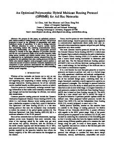
Because of the complexity of (6), it is, thus, not possible to find the closed-form expression of E[COVm ], but it can be acquired numerically. Example 1: Given R = 100 m and N = 100, when M = 1 and rs1 = 15 m, based on Theorem 1, we have E[COV1 ] = 0.8717, E[COV2 ] = 0.6164, and E[COV3 ] = 0.3529. On the other hand, if border effects are not considered, we have E[COV1 ] = 0.8946, E[COV2 ] = 0.6575, and E[COV3 ] = 0.3907. When M = 2, ρ1 = ρ2 = 0.5, rs1 = 10 m, and rs2 = 20 m, based on Theorem 1, we have E[COV1 ] = 0.8931, E[COV2 ] = 0.6634, and E[COV3 ] = 0.4058. Corollary 1: Given the radius of network R, the number of types of sensor nodes M , the sensing range of type i node rsi (1 ≤ i ≤ M ), and a small parameter ε(0 < ε < 1). When border effects are considered, �m−1 � the necessary number of nodes N should satisfy n1 +···+nM =x × x=0 � M 2 [ M W (k)W (k)/ n !] ≤ (ε/2)R to guarantee ex1 2 k=0 i=1 i pected m-coverage ratio E[COVm ] that is no less than 1 − ε, where W1 (k) and W2 (k) are shown in Theorem 1. Proof: According to Theorem 1, we have the conclusion as shown in Corollary 1. � Example 1 (Continued): Given R = 100 m, when M = 1 and rs1 = 15 m, based on Corollary 1, if border effects are considered, the deployed number of nodes is at least 34 to satisfy 50% one-coverage network, and the deployed number of nodes is at least 237 (350, 453) to satisfy network a.s. onecoverage (two-coverage, three-coverage); when M = 2, ρ1 = ρ2 = 0.5, rs1 = 10 m, and rs2 = 20 m, based on Corollary 1, the deployed number of nodes is at least 218 (323, 417) to satisfy network a.s. one-coverage (two-coverage, three-coverage). At the end of this section, given R = 100 m, we plot the relationship between expected m-coverage ratio E[COVm ](m = 1, 2, 3) and number of deployed nodes N , which is shown in Fig. 2. In Fig. 2(a), we observe that given the same number of nodes, the value of E[COVm ] under border effects is smaller than the value under no border effects. It is due to the fact that, in the latter case, it is assumed that the effective sensing areas of all nodes are completely contained within monitoring region Ω. However, it is not true for all nodes. Fig. 2(b) presents the case when region Ω consists of two types of nodes (i.e., M = 2). Fig. 2 also shows that the value of E[COVm ] is close to 1 infinitely when the number of nodes is larger than some threshold. In this case, the network region is a.s. m-covered.
Fig. 2. Expected m-coverage ratio E[COVm ] versus number of deployed nodes N . (a) M = 1, rs1 = 15 m. (b) M = 2, rs1 = 10 m, and rs2 = 20 m.
B. n-Connectivity Probability The connectivity of a wireless multihop network is one of its essential characteristics. Here, given the number of sensor nodes N , we calculate expected network n-connectivity probability E[CONn ] under border effects. The probability for a region to be n-connected depends on the node density and their radio ranges. Let G(rt_MIN ) be a directed communication graph that is formed by all nodes whose radio ranges are set to rt_MIN . The event of G(rt_MIN ) being n-connected is a necessary condition for a directed communication graph G to be n-connected, although it is not a sufficient condition. Here, graph G is defined in Definition 3. That is, the implication [G(rt_MIN ) is n-connected] ⇒ (G is n-connected) holds, but the reverse is not necessarily true. Thus P (G is n-connected) ≥ P [G(rt_MIN ) is n-connected] .
(7)
Since the nodes in G(rt_MIN ) have the same radio range, G(rt_MIN ) can be regarded as an undirected homogenous geometric graph. On the other hand, the event dm [G(rt_MIN )] ≥ n is a necessary condition for G(rt_MIN ) to be n-connected, although it is not a sufficient condition. Here, dm [G(rt_MIN )] denotes the degree of graph G(rt_MIN ). Therefore P [G(rt_MIN ) is n-connected] ≤ P {dm [G(rt_MIN )] ≥ n}. (8) In the following, we show that the upper bound of (8) is a very tight bound, in particular, for high probability values (close to 1), which is certainly most interesting. As a result, we can conclude that P [G(rt_MIN ) is n-connected] is approximately equal to P {dm [G(rt_MIN )] ≥ n}. Now, we apply a result on the property of geometric random graphs that was discussed in [25], where Penrose has proved that if N is large enough, then with a high probability, if one starts with an empty graph (i.e., only isolated nodes) and adds the corresponding links as the radio range increases, the resulting (undirected) graph becomes n-connected at the moment when it achieves a minimum node degree n, i.e., P [G(rt_MIN ) is n-connected] = P {dm [G(rt_MIN )] ≥ n} (9) for P {dm [G(rt_MIN )] ≥ n} almost 1. In fact, Penrose’s theorem was proven to be true for any lp metric in any dimension
Authorized licensed use limited to: University of Nevada Las Vegas. Downloaded on July 3, 2009 at 17:49 from IEEE Xplore. Restrictions apply.
1434
IEEE TRANSACTIONS ON VEHICULAR TECHNOLOGY, VOL. 58, NO. 3, MARCH 2009
that is higher than one; however, it is not valid in one dimension [25]. According to the definition of network n-connectivity (shown in Definition 4), we have P {dm [G(rt_MIN )] ≥ n} � P [d(u) ≥ n] = ∀u∈G(rt_MIN ) �
n−1 x � � ϕ = 1 − exp(−ϕ) x! x=0 ∀u∈G(rt_MIN )
(10)
where ϕ = N �Ω(u, rt_MIN ) ∩ Ω�/�Ω� is the expected number of nodes within the radio range of node u in G(rt_MIN ). Obviously, the value of ϕ depends on the position of node u and the value of rt_MIN . Similar to Fig. 1, we have � 2 N rt_MIN /R2, 0 < r = dis(u,O) ≤ R − rt_MIN ϕ= . N Ω (r, rt_MIN )/πR2, R − rt_MIN < r = dis(u,O) ≤ R (11) Summarily, the result of the network n-connectivity probability is shown in Theorem 2. Theorem 2: Consider that M types of sensor nodes are randomly distributed in a circular region with radius R. The minimal radio range of all nodes is denoted as rt_MIN . If border effects are considered, expected n-connectivity probability E[CONn ] provided by N nodes is given by ⎡ � � � N rt2_MIN 2 rt_MIN �2 ⎢ E[CONn ] ≥ ⎣1 − 1 − Y − 2 R R2 R �
�R ×
rY
N Ω (r, rt_MIN ) πR2
�
Because of the complexity of (12), it is, thus, not possible to find the closed-form expression of E[CONn ], but it can be acquired numerically. Example 2: Given R = 100 m and N = 100, when rt_MIN = 30 m, based on Theorem 2, we have E[CON1 ] ≥ 0.8566, E[CON2 ] ≥ 0.3749, and E[CON3 ] ≥ 0.0362. On the other hand, if border effects are not considered, we have E[CON1 ] ≥ 0.9877, E[CON2 ] ≥ 0.8838, and E[CON3 ] ≥ 0.5352. Corollary 2: Given the radius of network R, the number of types of sensor nodes M , the minimal radio range of all nodes rt_MIN , and a small parameter η (0 < η < 1). When border effects are considered and the number of nodes N satisfies ⎡ � � � N rt2_MIN rt_MIN �2 2 ⎢ −N ⎣ 1 − + 2 Y 2 R R R ⎤ � � �R N Ω (r, rt_MIN ) ⎥ × rY dr⎦ ≥ ln(1 − η) πR2 R−rt_MIN then expected n-connectivity probability E[CONn ] is not less than 1 − η, where Y (k) is shown in Theorem 2. Proof: According to Theorem 2 and the n-connectivity probability requirement, we should guarantee that ⎡ � � � N rt2_MIN 2 rt_MIN �2 ⎢ Y − 2 E[CONn ] ≥ ⎣1 − 1 − 2 R R R
×
⎤N ⎥ dr⎦
�
�R rY
N Ω (r, rt_MIN ) πR2
�
⎤N ⎥ dr⎦
R−rt_MIN
(12)
≥ 1 − η.
R−rt_MIN
Thus
� x where Y (k) = exp(−k) n−1 x=0 k /x!. Proof: Based on (7), (9), and (10) E[CONn ] = E [P (G is n-connected)] ⎧
⎫ � n−1 x ⎬ ⎨ � � ϕ ≥E . 1 − exp(−ϕ) ⎩ x! ⎭ x=0 ∀u∈G(rt_MIN ) Because the distribution of nodes is independent, therefore ⎧ �
⎫ n−1 x ⎬ ⎨ � � ϕ E 1 − exp(−ϕ) ⎩ x! ⎭ x=0 ∀u∈G(rt_MIN ) �
!N n−1 x � ϕ = E 1 − exp(−ϕ) . x! x=0 Integrated with (11), we have the result as (12). � On the other hand, when border effects are ignored, we have � E[CONn ] ≥ 1 − Y
�
N rt2_MIN R2
� N .
⎡
� rt_MIN �2 ⎢ N ln ⎣1 − 1 − Y R �
�R ×
rY
�
N rt2_MIN R2
�
N Ω (r, rt_MIN ) πR2
− �
2 R2 ⎤
⎥ dr⎦ ≥ ln(1 − η).
R−rt_MIN
Because ln(1 + x) → x when x → 0, we then have ⎡ � � � N rt2_MIN 2 rt_MIN �2 ⎢ Y + 2 −N ⎣ 1 − 2 R R R �
�R ×
rY
N Ω (r, rt_MIN ) πR2
�
⎤ ⎥ dr⎦ ≥ ln(1 − η).
R−rt_MIN
As a result, Corollary 2 can be proved. � Example 2 (Continued): Given R = 100 m and rt_MIN = 30 m, based on Corollary 2, if border effects are considered,
Authorized licensed use limited to: University of Nevada Las Vegas. Downloaded on July 3, 2009 at 17:49 from IEEE Xplore. Restrictions apply.
JIN et al.: EECCR: ENERGY-EFFICIENT m-COVERAGE AND n-CONNECTIVITY ROUTING ALGORITHM
1435
Here, the values of m and n can be adjusted according to the different application requirement for fault tolerance. We refer to this problem as the energy-efficient m-coverage and n-connectivity problem.
B. Algorithm Description
Fig. 3. Lower bound of expected n-connectivity probability E[CONn ] versus number of deployed nodes N .
165 (222, 272) nodes are guaranteed to achieve network a.s. one-connectivity (two-connectivity, three-connectivity), i.e., E[CONn ] ≥ 0.99. Recall that Example 1 has mentioned that 237 (350, 453) nodes can achieve network a.s. one-coverage (two-coverage, three-coverage) when M = 1 and rs1 = 15 m. These numerical results validate the important conclusion in [19]: “In homogenous network region, the communication range rt is at least twice of the sensing range rs ” is the sufficient condition (instead of the necessary condition) to ensure that a full m-coverage of a convex area implies n-connectivity among active nodes that are inside the convex area, given m = n. At the end of this section, given R = 100 m and rt_MIN = 30 m, we plot the relationship between expected n-connectivity probability E[CONn ](n = 1, 2, 3) and number of deployed nodes N , which is shown in Fig. 3. In Fig. 3, given the value of R, to achieve the desired network n-connectivity probability, we can find the corresponding number of deployed nodes by numerical solution. This figure also shows that the network n-connectivity probability is close to 1 infinitely when the number of nodes is larger than some threshold. In this case, the network is a.s. n-connected. Furthermore, when rti = 2rsi (1 ≤ i ≤ M ), compared with Figs. 2 and 3, we observe that fewer nodes should be deployed to achieve network m-coverage ratio 1 − ε than to achieve network n-connectivity probability 1 − η, given m = n and 0 < ε = η < 1. V. E NERGY -E FFICIENT m-C OVERAGE AND n-C ONNECTIVITY R OUTING A LGORITHM : THE EECCR A. Problem Formulation Given: a circular interested region Ω that consists of M types of sensor nodes. The number of sensor nodes is N . For the type i node, its sensing range and radio range are rsi and rti , respectively. Objective: maximizing the network lifetime. Constraints: at any moment 1) the ratio of the network m-coverage area is not less than 1 − ε, where ε is specified by the application; 2) each active node is able to communicate with the sink node by at least n mutually independent minimal hop count paths, directly or through relay nodes.
In Section IV, we have analyzed the network m-coverage ratio and the network n-connectivity probability under border effects, respectively. Motivated by these results, we propose a location-independent energy-efficient routing algorithm, called the EECCR, to solve the problem mentioned in Section V-A. The data collection operation is broken up into rounds, where each round begins with a routing setup phase, i.e., each node independently builds n-connected minimal hop count routing paths, and then a data transmission phase, i.e., the members within each scheduling set periodically transmit the sensed data to the sink node. To minimize the algorithm overhead, the interval of data transmission phase TD is long compared with that of routing setup phase TR . 1) Routing Setup Phase: The operation of this phase is composed of three steps. Step 1 divides the nodes into mutually exclusive scheduling sets, and each node randomly joins any scheduling set such that the m-coverage ratio that is provided by the members within each scheduling set is not less than 1−ε. Step 2 determines the minimal hop count of each node. Step 3 constructs n-connected minimal hop count routing paths for each member within any scheduling set. The detailed process is described as follows. Step 1) Dividing the nodes into mutually exclusive scheduling sets. We assume the original network before scheduling is m-covered and n-connected completely. To solve the energy-efficient m-coverage and nconnectivity problem, it needs at least NAC (m, ε, n) active nodes at any moment. Here, NAC (m, ε, n) = max{NCOV (m, ε), NCON (n)}, where NCOV (m, ε) is the minimal number of nodes to achieve the desired network m-coverage ratio 1 − ε, and NCON (n) is the number of nodes to achieve a.s. network n-connectivity. The values of NCOV (m, ε) and NCON (n) can be obtained from Corollaries 1 and 2, respectively. Then, the nodes will be divided into s (= �N (t)/NAC (m, ε, n)�) mutually exclusive scheduling sets, where N (t) is the number of available nodes at moment t. Obviously, we have N (0) = N . If s < 1, then the lifetime of the network expires because all available nodes cannot provide the sufficient network m-coverage ratio or the network n-connectivity probability. Otherwise (i.e., s ≥ 1), each node u independently generates a random integer number su between 0 and s − 1 (0 and s − 1 inclusive) as its scheduling number. Step 2) Determining the minimal hop count of each node. Initially, each node maintains a routing table. Each item in this table corresponds to the information (e.g., the node ID, the node hop count,
Authorized licensed use limited to: University of Nevada Las Vegas. Downloaded on July 3, 2009 at 17:49 from IEEE Xplore. Restrictions apply.
1436
IEEE TRANSACTIONS ON VEHICULAR TECHNOLOGY, VOL. 58, NO. 3, MARCH 2009
and the node scheduling number) of a different neighbor node. The sink node first broadcasts a hello message with radio range rt_max , where rt_max is the maximal radio range of all nodes. The initial hop count of the sink node is set to 0, whereas the hop counts of other nodes are set to be indefinite. When a type i node u receives a hello message from node v (sink node inclusive), it will estimate the distance from node v based on the receiving signal intensity. If rti ≤ dis(u, v), node u will ignore this hello message. Otherwise, node u will set node v as its neighbor node. Then, node u initializes a back-off timer TS1 , where TS1 is a system parameter. Before the timer expires, if node u receives another hello message from a node w and dis(u, w) ≤ rti , it will also add the information of node w to its routing table as another neighbor node. After the timer expires, the hop count of node u will be determined, as the minimal hop count of all node u’s neighbor nodes increased by one. Then, node u forwards a hello message with radio range rt_max , piggybacking its ID, its hop count, and its scheduling number. Note in the above description that the advantage of backoff timer TS1 is that the node can obtain its minimal hop count (to the sink node). Although a large backoff timer will increase the total time that is required for the completion of this step, we argue that it is an effective solution because this step is a one-time task for static sensor networks, and it avoids extra forwarded messages to be produced. After all, the energy is the most precious resource for nodes. Step 3) Constructing n-connected minimal hop count routing paths. After step 1, each node has obtained its scheduling number. However, because the scheduling number that is generated by the node is random, there is no guarantee on the n-connectivity of each scheduling set. Thus, step 3 is introduced to ensure that each scheduling set is n-connected, which can be approximately achieved if each member has at least n neighbors in the same scheduling set. Moreover, step 3 also needs to guarantee that the hop counts of n mutually routing paths from any member within each scheduling set to the sink node are minimal, which can minimize the transmission latency. Variable SNu (t) denotes the scheduling number set of node u at moment t. Initially, we have SNu (0) = {su }. Here, su is the scheduling number of node u, which is obtained in step 1. For any node u at moment t1 , based on the routing table formed in step 2, it first selects n neighbor nodes with the minimal hop counts as its next hop nodes (to the sink node). Then, node u will send the notify messages to these selected nodes, piggybacking its ID and its scheduling number set SNu (t1 ). If some node, for example, node v, receives a notify message at moment t2 , then it will update its scheduling number set
as SNv (t2 ) = SNv (t2 ) ∪ SNu (t1 ). After that, node v will select its n neighbor nodes with the minimal hop counts as its next hop nodes and send the notify messages to these selected nodes, piggybacking its ID and its new scheduling number set SNv (t2 ). It is possible that a node has to send the notify messages multiple times if it receives multiple notify messages from its neighbor nodes. To minimize the number of notify messages that each node sends, a back-off timer scheme that is similar to step 2 also needs to be applied here. Note that each node should have a different back-off timer because the node with hop count h should wait for messages from the node with hop count h + 1; thus, the node with a smaller hop count should wait longer. Given region radius R and the minimal radio range of all nodes rt_min , maximal hop count hmax for all nodes can be approximately estimated as hmax = �2R/rt_min �. Therefore, back-off timer TS2 (h) for an h-hop node can be set as TS2 (h) = (1 − h/hmax )TS2 , where TS2 is a system parameter. At the end of step 3, some nodes are included in multiple scheduling sets, i.e., some nodes will have to be activated in multiple scheduling sets, and thus, these scheduling sets are no longer mutually exclusive. Furthermore, in any scheduling set, each member can find n mutually connected minimal hop count routing paths. We note that, by receiving the notify messages, each node knows its previous hop nodes with the same scheduling set. Therefore, another advantage of step 3 is that before each node transmits the data to its n next hop nodes, it is eligible to wait for aggregating the received data from its previous nodes to reduce the network traffic, which reduces the energy consumption of the communication for each node. 2) Data-Transmission Phase: After the minimal hop count routing paths are formed, the members of scheduling set 0, scheduling set 1, . . ., scheduling set s − 1 start periodically transmitting the collected data to the sink node, where s is the number of scheduling sets. Only one scheduling set works at any moment. After the members of scheduling set l have worked for interval TD /s, the members of scheduling set (l + 1) mod s are scheduled to work for next interval TD /s. By such a round-robin fashion, the proposed algorithm balances the energy consumption of the node. Furthermore, each scheduling set can simultaneously maintain the specific network m-coverage ratio and the network n-connectivity. C. Algorithm Illustration An example of solving the energy-efficient m-coverage and two-connectivity problem is illustrated in Fig. 4. Assume that the network consists of one sink node and nine sensor nodes (e.g., A, B, C, D, E, F, G, H, and I), which is shown in Fig. 4(a). Step 1) According to the m-coverage ratio and the n-connectivity requirement, it is assumed that the
Authorized licensed use limited to: University of Nevada Las Vegas. Downloaded on July 3, 2009 at 17:49 from IEEE Xplore. Restrictions apply.
JIN et al.: EECCR: ENERGY-EFFICIENT m-COVERAGE AND n-CONNECTIVITY ROUTING ALGORITHM
1437
TABLE II SIMULATION PARAMETERS
Fig. 4.
Example of an EECCR algorithm illustration.
nodes are divided into four mutually exclusive scheduling sets. H, I, and A are assigned to scheduling number 0; G, E, and B are assigned to scheduling number 1; F is assigned to scheduling number 2; and D and C are assigned to scheduling number 3, respectively. The scheduling number set of each node is shown in the bracket of Fig. 4(a). Step 2) By receiving the hello messages from the neighbor nodes, each node obtains its minimal hop count (to the sink node) and the information of its neighbor nodes. For example, G, H, and I are three hops away; D, E, and F are two hops away; and A, B, and C are one hop away from the sink node. The arrows of Fig. 4(b) represent the relationship between the node and its neighbor node, i.e., for node E, it has five neighbor nodes (e.g., A, B, C, D, and F); for node B, it has four neighbor nodes (e.g., A, sink node, C, and D). Step 3) Based on the back-off timer scheme, first, nodes G, H, and I send their notify messages. In this case, node G selects nodes D and E; node H selects nodes E and F; and node I selects nodes E and F as the next hops, respectively. Accordingly, two-hop nodes D, E, and F will update their scheduling number sets, as shown in Fig. 4(c). After their back-off timers expire, one-hop nodes D, E, and F begin to construct two connected minimal hop count paths, respec-
tively. For node D, it will send notify messages to nodes A and B. The updated scheduling number sets of nodes A and B are shown in Fig. 4(d). For node E, it can send notify messages to any two nodes among nodes A, B, and C. Now, there are two cases. 1) Before node E sends notify messages, it hears that node D has sent notify messages to nodes A and B. In this case, to reduce the energy consumption of node C, node E will send notify messages to nodes A and B. After that, the scheduling number sets of nodes A, B, and C are shown in Fig. 4(e). 2) Before node E sends notify messages, it does not hear that node D has sent notify messages to nodes A and B. In this case, it is possible for node E to send notify messages to nodes B and C. After that, the scheduling number sets of nodes A, B, and C are shown in Fig. 4(f). After step 3, the scheduling sets are constructed as follows. Scheduling set 0 consists of nodes H, I, E, F, A, B, and C; scheduling set 1 consists of nodes G, D, E, A, and B [case (1), as shown in Fig. 4(e)] or G, D, E, A, B, and C [case (2), as shown in Fig. 4(f)]; scheduling set 2 consists of nodes F, B, and C; scheduling set 3 includes nodes D, A, B, and C. Obviously, the members in each scheduling set maintain two connected minimal hop count routing paths. Furthermore, the desired coverage ratio is guaranteed because the number of members for each scheduling set is not less than NAC (m, ε, n). Then, in the data-transmission phase, each scheduling set works periodically. VI. S IMULATION R ESULTS In this section, the simulation experiments are executed to compare the EECCR algorithm with two typical coverage preserving algorithms—the CCP [19] and the Liu et al. algorithm [20]. The latter two algorithms are merely designed for homogenous sensor networks. The CCP provides a solution to achieve full m-coverage and m-connectivity, and the Liu et al. algorithm provides a solution to achieve full/partial one-coverage and one-connectivity. Comparably, the EECCR provides a solution to achieve full/partial m-coverage and n-connectivity in homogenous/heterogeneous sensor networks. We use Ns-2 [26], i.e., a discrete event-driven network simulator, to acquire our simulation results. The basic simulation parameters are shown in Table II. To measure the coverage, we divide the entire circular region into circle-shaped small patches with a radius of 1 m. The
Authorized licensed use limited to: University of Nevada Las Vegas. Downloaded on July 3, 2009 at 17:49 from IEEE Xplore. Restrictions apply.
1438
IEEE TRANSACTIONS ON VEHICULAR TECHNOLOGY, VOL. 58, NO. 3, MARCH 2009
Fig. 5. Simulation result of full one-coverage and one-connectivity in a homogenous sensor network. (a) Number of active sensor nodes versus the value of rt /rs . (b) Achieved network one-coverage ratio versus the value of rt /rs . (c) Packet delivery ratio versus the value of rt /rs . (d) Packet transmission latency versus the value of rt /rs .
coverage degree of a patch is approximately calculated by measuring the number of nodes that cover the center of the patch. That is, the patch is m-covered when the center of the patch lies in at least m sensor nodes. In the following experiments, each was executed 100 times to get more reliable results. For each time, ten different random network topologies are generated. The simulation results are plotted using the average values that are derived from these networks, with a 95% confidence interval. Some performance metrics are introduced to compare the different algorithms. 1) Number of active nodes: a measure of algorithm efficiency to simultaneously achieve the desired network m-coverage ratio and the network n-connectivity. 2) Network m-coverage ratio: a measure of coverage quality. 3) Packet delivery ratio: the ratio of the total number of data received at the sink node over the total number of transmitted data from active nodes. Because the traffic load is very light, this metric is an indicator of network connectivity. 4) Packet transmission latency: the time interval from the moment when the data packet is generated to the moment
when the sink node receives this data packet. The packet transmission latency will decrease if more nodes that are active have the minimal hop count routing paths in the network. This metric is an indicator of routing path optimality. A. Full One-Coverage and One-Connectivity Problem To fairly compare the EECCR, the CCP, and the Liu et al. algorithm, a homogenous sensor network is considered. Given the radius of region R and the sensing range of node rs (as shown in Table II), we change the value of rt /rs to get the number of active nodes, where rt is the radio range of the node. The result is plotted in Fig. 5(a). In Fig. 5(a), we observe that the number of active nodes in the CCP and the EECCR is nearly the same when rt /rs ≥ 2. For example, when rt /rs = 2, the number of active nodes in the CCP and the EECCR is 543 and 513, respectively. When rt /rs < 2, the number of active nodes in the CCP and the EECCR is different. In this case, compared with the CCP algorithm, the EECCR is more energy-efficient because it has less-active sensor nodes. For example, when rt /rs = 1.5, the number of active nodes in the CCP and the EECCR is 682 and 583, respectively. The reason is that when rt < 2rs , the
Authorized licensed use limited to: University of Nevada Las Vegas. Downloaded on July 3, 2009 at 17:49 from IEEE Xplore. Restrictions apply.
JIN et al.: EECCR: ENERGY-EFFICIENT m-COVERAGE AND n-CONNECTIVITY ROUTING ALGORITHM
1439
Fig. 6. Simulation result of full m-coverage and m-connectivity in a homogenous sensor network. (a) Number of active sensor nodes versus the value of rt /rs . (b) Achieved network m-coverage ratio versus the value of rt /rs . (c) Packet delivery ratio versus the value of rt /rs . (d) Packet transmission latency versus the value of rt /rs .
CCP integrates the connectivity-centric algorithm SPAN [12] to maintain the network one-connectivity. The SPAN algorithm selects the nodes not only to meet network connectivity but to avoid suffering a significant loss of capacity or increased transmission latency simultaneously as well. Therefore, some redundant nodes are activated by the CCP. We notice in Fig. 5(a) that both the number of active nodes in the CCP and the EECCR are larger than that of the active nodes in the Liu et al. algorithm. This is expected because the Liu et al. algorithm does not take into account the border effects. The Liu et al. algorithm thinks that the sensing areas of all nodes are completely included in the network. Although the number of active nodes in the Liu et al. algorithm is small, in fact, it does not achieve the full onecoverage without the sufficient sensor nodes. This observation is validated in Fig. 5(b). Furthermore, we notice that the achieved network coverage ratio is inversely proportional to the value of rt /rs in these algorithms. The reason is that when the ratio range of the node increases, there are fewer nodes that belong to multiple scheduling sets. The packet delivery ratio is shown in Fig. 5(c), which means that the network can be preserved to be a.s. one-connected in the CCP, the
Liu et al. algorithm, and the EECCR. Fig. 5(d) demonstrates that the packet transmission latency of the EECCR and the Liu et al. algorithm is less than that of the CCP. This is because only the nodes in the EECCR and the Liu et al. algorithm utilize the minimal hop count paths (to the sink node) during communications. Another observation from this figure is that in the EECCR and the Liu et al. algorithm, the packet transmission latency is inversely proportional to the value of rt /rs , which is expected since when the radio range of the node increases, each node is able to find more neighbor nodes with minimal hop counts as its next hop nodes. Fig. 5 shows that these three algorithms can achieve the one-connectivity requirement. Compared with the CCP and the EECCR, the Liu et al. algorithm cannot provide the full onecoverage requirement. B. Full m-Coverage and m-Connectivity Problem (m > 1) In a homogenous sensor network, we change the value of rt /rs to get the number of active nodes. The result is plotted in Fig. 6(a). The corresponding network m-coverage ratio is shown in Fig. 6(b). Note that, because the aim of the
Authorized licensed use limited to: University of Nevada Las Vegas. Downloaded on July 3, 2009 at 17:49 from IEEE Xplore. Restrictions apply.
1440
IEEE TRANSACTIONS ON VEHICULAR TECHNOLOGY, VOL. 58, NO. 3, MARCH 2009
TABLE III SIMULATION RESULTS OF THE LIU et al. ALGORITHM
Liu et al. algorithm is to solve the full one-coverage and oneconnectivity problem, we only provide the results of the CCP and the EECCR in Fig. 6. To verify the network m-connectivity capacity provided by the EECCR and the CCP, m − 1 active nodes are randomly turned off for each round. In this case, the packet delivery ratio and the transmission latency are plotted in Fig. 6(c) and (d), respectively. Fig. 6(c) indicates that the CCP and the EECCR still can preserve a high connectivity probability (close to 1), although m − 1 active nodes are disabled. Furthermore, compared with Fig. 5(d), Fig. 6(d) shows that the packet transmission latency of both algorithms remains stable, even in an unreliable scenario. This is because each active node can still find a feasible minimal hop count routing path when m − 1 active nodes are disabled. Fig. 6 shows that the EECCR and the CCP can achieve full m-coverage and m-connectivity. Compared with the CCP, the advantages of the EECCR are as follows. 1) It does not need location information. 2) It needs less message exchange. 3) It provides shorter transmission latency. C. Partial One-Coverage and One-Connectivity Problem Given a predetermined network coverage ratio 1 − ε, because the aim of the CCP algorithm is merely to solve the full m-coverage and m-connectivity problem, we only provide the results of the Liu et al. algorithm and the EECCR, which are shown in Tables III and IV, respectively. From Tables III and IV, we observe that only the EECCR algorithm achieves the application requirement all the time, that is, the EECCR can simultaneously preserve the desired network one-coverage ratio and the network one-connectivity. Comparably, the Liu et al. algorithm occasionally meets the application requirement because it ignores the impact of border effects.
TABLE IV SIMULATION RESULTS OF THE EECCR
D. Homogenous/Heterogeneous Partial m-Coverage and n-Connectivity Problem Compared with the CCP and the Liu et al. algorithm, only the EECCR provides a solution to address this homogenous/heterogeneous partial m-coverage and n-connectivity problem. Therefore, given the desired values of network coverage ratio 1 − ε, m, and n, the EECCR is executed to obtain the simulation results. The results show that the EECCR can achieve the desired application requirement (i.e., the achieved m-coverage ratio is larger than 1 − ε, and the achieved n-connectivity probability is larger than 0.99), which is not presented here. In summary, the extensive simulation results in this section show that the EECCR algorithm solves the m-coverage with a desired ratio and n-connectivity problem in homogenous/ heterogeneous sensor networks. Finally, we conclude the main performance metrics of the CCP, the Liu et al. algorithm, and the EECCR in Table V. VII. C ONCLUSION In this paper, we have studied the energy-efficient m-coverage and n-connectivity problem under border effects in heterogeneous sensor networks. The theorems/corollaries that we have derived are very useful in estimating the monitoring and connectivity capacity when a number of nodes are distributed randomly. Then, we have presented a locationindependent, energy-efficient routing algorithm EECCR to simultaneously maintain the network m-coverage ratio and the network n-connectivity. In the routing setup phase, the members of each scheduling set are formed to satisfy the partial m-coverage and a.s. n-connectivity requirement. Then, in the data transmission phase, each scheduling set periodically works to reduce and balance the energy consumption of the node. The back-off timer-based scheme has also been introduced to reduce the algorithm overhead. Finally, we have conducted extensive experiments by simulation to evaluate the performance of the
Authorized licensed use limited to: University of Nevada Las Vegas. Downloaded on July 3, 2009 at 17:49 from IEEE Xplore. Restrictions apply.
JIN et al.: EECCR: ENERGY-EFFICIENT m-COVERAGE AND n-CONNECTIVITY ROUTING ALGORITHM
1441
TABLE V ALGORITHM COMPARISON
proposed algorithm, which demonstrates the correctness of our algorithm. There are still a few other issues that should be explored further. An improved algorithm should be designed so that the interested region can be evenly m-covered with a desired ratio by the active nodes. Another direction is to schedule the sensor nodes with the different initial energy in an energy-efficient approach, while simultaneously preserving the network coverage and network-connectivity requirements. ACKNOWLEDGMENT The authors would like to thank the anonymous reviewers for their constructive comments and suggestions that greatly helped improve the final quality of this paper. R EFERENCES [1] I. F. Akyildiz, W. Su, Y. Sankarasubramaniam, and E. Cayirci, “Wireless sensor networks: A survey,” Comput. Netw., vol. 38, no. 4, pp. 393–422, 2002. [2] E. Deborah, G. Ramesh, J. Heidemann, and S. Kumar, “Next century challenges: Scalable coordination in sensor networks,” in Proc. 5th ACM/IEEE Annu. Int. Conf. Mobile Comput. Netw. MOBICOM, 1999, pp. 263–270. [3] J. M. Rabaey, M. J. Ammer, J. L. da Silva, D. Patel, and S. Roundy, “PicoRadio supports ad hoc ultra-low power wireless networking,” Computer, vol. 33, no. 7, pp. 42–48, Jul. 2000. [4] J. M. Kahn, R. H. Katz, and K. S. J. Pister, “Next century challenges: Mobile networking for ‘smart dust’,” in Proc. 5th ACM/IEEE Annu. Int. Conf. Mobile Comput. Netw. MOBICOM, 1999, pp. 271–278. [5] K. Akkaya and M. Younis, “A survey on routing protocols for wireless sensor networks,” Ad Hoc Netw., vol. 3, no. 3, pp. 325–349, May 2005. [6] W. Ye, J. Heidemann, and D. Estrin, “An energy-efficient MAC protocol for wireless sensor networks,” in Proc. 21st IEEE Conf. Comput. Commun. INFOCOM, 2002, pp. 1567–1576. [7] W. Heinzelman, A. Chandrakasan, and H. Balakrishnan, “Energy-efficient routing protocols for wireless microsensor networks,” in Proc. 33rd HICSS, 2000, pp. 3005–3014. [8] O. Younis and S. Fahmy, “HEED: A hybrid, energy-efficient, distributed clustering approach for ad hoc sensor networks,” IEEE Trans. Mobile Comput., vol. 3, no. 4, pp. 366–379, Oct./Dec. 2004. [9] S. Bandyopadhyay and E. J. Coyle, “Minimizing communication costs in hierarchically-clustered networks of wireless sensors,” Comput. Netw., vol. 44, no. 1, pp. 1–16, Jan. 2004. [10] Y. Jin, L. Wang, Y. Kim, and X. Z. Yang, “EEMC: An energy efficient multi-level clustering algorithm for large-scale wireless sensor networks,” Comput. Netw., vol. 52, no. 3, pp. 542–562, Feb. 2008. [11] P. Gupta and P. R. Kumar, “Critical power for asymptotic connectivity in wireless networks,” Stochastic Analysis, Control, Optimization and Applications: A Volume in Honor of W.H. Fleming, W. M. McEneany, G. Yin, and Q. Zhang, Eds. Boston, MA: Birkhäuser, 1998, pp. 547–566. [12] B. Chen, K. Jamieson, H. Balakrishnan, and R. Morris, “Span: An energyefficient coordination algorithm for topology maintenance in ad hoc wireless networks,” in Proc. 7th ACM/IEEE Annu. Int. Conf. Mobile Comput. Netw. MOBICOM, 2001, pp. 85–96. [13] F. Ye, G. Zhong, S. Lu, and L. Zhang, “PEAS: A robust energy conserving protocol for long-lived sensor networks,” in Proc. 23rd ICDCS, 2003, pp. 28–37.
[14] D. Tian and N. D. Georganas, “A coverage-preserving node scheduling scheme for large wireless sensor networks,” in Proc. 1st ACM Int. Workshop WSNA, 2002, pp. 32–41. [15] S. Slijepcevic and M. Potkonjak, “Power efficient organization of wireless sensor networks,” in Proc. IEEE ICC, 2001, pp. 472–476. [16] H. Gupta, S. R. Das, and Q. Y. Gu, “Connected sensor cover: Selforganization of sensor networks for efficient query execution,” IEEE/ACM Trans. Netw., vol. 14, no. 1, pp. 55–67, Feb. 2006. [17] Z. Zhou, S. Das, and H. Gupta, “Connected k-coverage problem in sensor networks,” in Proc. ICCCN, 2004, pp. 373–378. [18] H. H. Zhang and J. C. Hou, “Maintaining sensing coverage and connectivity in large sensor networks,” Int. J. Wireless Ad Hoc Sensor Netw., vol. 1, no. 1/2, pp. 89–124, 2005. [19] X. R. Wang, G. L. Xing, Y. F. Zhang, C. Y. Lu, R. Pless, and C. Gill, “Integrated coverage and connectivity configuration in wireless sensor networks,” in Proc. 1st Int. Conf. Embedded Netw. SENSYS, 2003, pp. 28–39. [20] C. Liu, K. Wu, Y. Xiao, and B. Sun, “Random coverage with guaranteed connectivity: Joint scheduling for wireless sensor networks,” IEEE Trans. Parallel Distrib. Syst., vol. 17, no. 6, pp. 562–574, Jun. 2006. [21] M. Cardei and J. Wu, “Energy-efficient coverage problems in wireless ad-hoc sensor networks,” Comput. Commun., vol. 29, no. 4, pp. 413–420, 2005. [22] C. Bettstetter and J. Zangl, “How to achieve a connected ad hoc network with homogeneous range assignment: An analytical study with consideration of border effects,” in Proc. 4th Int. Workshop Mobile Wireless Commun. Netw., 2002, pp. 125–129. [23] V. Loscri and S. Marano, “A new geographical multipath protocol for ad hoc networks to reduce the route coupling phenomenon,” in Proc. IEEE Int. VTC, 2006, pp. 1102–1106. [24] [Online]. Available: http://mathworld.wolfram.com/CircleCircleIntersection.html [25] M. D. Penrose, “On k-connectivity for a geometric random graph,” Random Struct. Algorithms, vol. 15, no. 2, pp. 145–164, Sep. 1999. [26] VINT Project, The ucb/lbnl/vint Network Simulator-ns. [Online]. Available: http://www.isi.edu/nsnam/ns
Yan Jin received the B.S., M.S., and Ph.D. degrees in computer science from Harbin Institute of Technology, Harbin, China, in 2001, 2003, and 2008, respectively. He is currently a Research Associate with the Department of Electrical and Computer Engineering, University of Nevada, Las Vegas. His research interests include network security, ad hoc networks, wireless sensor networks, and wireless mesh networks.
Ling Wang received the B.S. degree in mathematics and the M.S. degree in control engineering from the Heilongjiang University, Harbin, China, in 1992 and 1995, respectively, and the Ph.D. degree in electrical engineering from the University of Nevada, Las Vegas, in 2003. In 2004, she joined the faculty of the College of Computer Science and Technology, Harbin Institute of Technology, as an Assistant Professor. Her research interests include VLSI design, various aspects of computer-aided design, hardware–software codesign, high-level synthesis, and low-power system design.
Authorized licensed use limited to: University of Nevada Las Vegas. Downloaded on July 3, 2009 at 17:49 from IEEE Xplore. Restrictions apply.
1442
IEEE TRANSACTIONS ON VEHICULAR TECHNOLOGY, VOL. 58, NO. 3, MARCH 2009
Ju-Yeon Jo received the Ph.D. degree in computer science from Case Western Reserve University, Cleveland, OH. She spent several years in communication networking and the software industry. She was a Member of Technical Staff with Lucent Technologies, Bell Labs, Homdel, NJ, and was a Software Engineer with Coree Networks: a New Jersey-based startup company. From 2003 to 2006, she was an Assistant Professor with the Department of Computer Science, California State University, Sacramento. Since August 2006, she has been an Assistant Professor with the School of Informatics, University of Nevada, Las Vegas. Her current research interests include information security, network security, networking protocol design and performance analysis, and Internet traffic characterization.
Yoohwan Kim (M’04) received the B.S. degree in economics from Seoul National University, Seoul, Korea, in 1989 and the M.S. and Ph.D. degrees in computer engineering from Case Western Reserve University, Cleveland, OH, in 1994 and 2004, respectively. Between 1997 and 1999, he was a Member of Technical Staff with Lucent Technologies, Whippany, NJ, where he developed software for wireless networking equipment. In 2000, he cofounded and managed a New Jersey-based software company that developed technologies for delivering and customizing video advertising over the Internet. Since 2004, he has been an Assistant Professor of computer science with the University of Nevada, Las Vegas. His current research interests include network security, Internet traffic analysis, and software architecture. Dr. Kim is a member of the IEEE Computer Society.
Mei Yang (M’03) received the Ph.D. degree in computer science from The University of Texas at Dallas, Richardson, in 2003. From August 2003 to August 2004, she was appointed Assistant Professor with the Department of Computer Science, Columbus State University, Columbus, GA. She is currently an Assistant Professor with the Department of Electrical and Computer Engineering, University of Nevada, Las Vegas. Her research interests include wireless sensor networks, network survivability and security, switch scheduling and control, computer architecture, and embedded systems.
Yingtao Jiang (M’01) received the B.S. degree in biomedical engineering and electronics from Chongqing University, Chongqing, China, in 1993, the M.S. degree in electrical engineering from Concordia University, Montreal, QC, Canada, in 1997, and the Ph.D. degree in computer science from The University of Texas at Dallas, Richardson, in 2001. He is currently an Associate Professor with the Department of Electrical and Computer Engineering, University of Nevada, Las Vegas. His research interests include algorithms, VLSI architectures, and circuit-level techniques for the design of DSP, networking, and telecommunications systems; computer architectures; and biomedical signal processing, instrumentation, and medical informatics.
Authorized licensed use limited to: University of Nevada Las Vegas. Downloaded on July 3, 2009 at 17:49 from IEEE Xplore. Restrictions apply.