Ching-Chuan Chiang, Hsiao-Kuang Wu, Winston Liu, and Mario Gerla. âRouting in Clustered Multihop, Mobile Wireless Networks with Fading. Channelâ ...
Hybrid Cluster Routing: An Efficient Routing Protocol for Mobile Ad Hoc Networks Xiaoguang Niu123, Zhihua Tao2, Gongyi Wu2, Changcheng Huang4, Li Cui1 1
Institute of Computing Technology, Chinese Academy of Sciences, Beijing, China 100080 Department of Computer Science and Technology, Nankai University, Tianjin, China 300071 3 Graduate University of Chinese Academy of Sciences, Beijing, China 100049 4 Department of Systems and Computer Engineering, Carleton University, Ottawa, Canada
2
Abstract – Routing is one of the fundamental but challenging issues in mobile ad hoc networks. During the past several years, a large number of routing protocols have been proposed, which can basically be categorized into three different groups including proactive/table-driven, reactive/on-demand, and hybrid. In this paper, we propose a novel hybrid routing protocol for large scale mobile ad hoc networks, namely HCR (Hybrid Cluster Routing). Here nodes are organized into a hierarchical structure of multi-hop clusters using a stable distributed clustering algorithm. Each cluster is composed of a clusterhead, several gateway nodes, and other ordinary nodes. The clusterhead is responsible for maintaining local membership and global topology information. In HCR, the acquisition of intra-cluster routing information operates in an on-demand fashion and the maintenance of inter-cluster routing information acts in a proactive way. Simulation results show that HCR conduces better scalability, robustness and adaptability to large scale mobile ad hoc networks compared with some well-known routing protocols, e.g. AODV, DSR, and CBRP. Keywords – mobile ad hoc network, reactive, proactive, hybrid routing, clustering. I. INTRODUCTION Wireless mobile ad hoc networks (MANETs) are composed of a collection of mobile independent nodes. In recent years, a great number of routing protocols have been developed to accommodate these specific networks. The proposed protocols can basically be grouped into three different categories: proactive/table-driven, reactive/on-demand, and hybrid [1]. In a proactive routing protocol, each node is required to maintain routing tables by using periodic updates to track the changes in network topology. This approach has the advantage that a route is generally available when needed. However it requires regular routing updates which may consume a large portion of limited network resources. Moreover, most of route information may never be used due to rapid node mobility and frequent topology changes. Therefore, proactive routings are more suitable for small scale MANETs with low node mobility and heavy traffic. DSDV [2], WRP [3], CGSR [4], and OLSR [5] are examples of this type of protocols. Reactive routing protocols, on the other hand, create and maintain routes only to meet current demands. These protocols thereby only incur overhead for route construction and maintenance when those routes are actually needed. They do not maintain routes that are not utilized. However, the route discovery is time consuming, thus producing a relatively long route acquisition latency that is undesirable in real-time and interactive communications. Examples of this type of protocols are AODV [6], DSR [7], and TORA [8]. An approach for a better trade-off between proactive and reactive routing is by using hybrid routing protocols, which is
both proactive and reactive in their nature. These protocols are designed to increase scalability by allowing nodes with close proximity to work together as a zone or cluster. This is achieved mostly by proactively maintaining routes to nearby nodes and determining routes to distant nodes using an on-demand route discovery strategy. Previous experiments show that hybrid protocols can provide a better compromise between communication overhead and delay as well as better scalability. Several hybrid routing protocols, such as ZRP [9], ZHLS [10] and CBRP [11], have been proposed during the recently years. In this paper, we will investigate a novel hybrid and cluster-based routing protocol named as “HCR (Hybrid Cluster Routing)” for large scale mobile ad hoc networks, aiming to acquire a better balance between routing overhead and latency delay than previous protocols. For the purpose of routing, nodes are organized into a hierarchical structure of multi-hop clusters, using an efficient and distributed clustering algorithm. Each cluster is composed of a distinguished node called clusterhead, several gateway nodes which are located between multiple clusters, and a number of ordinary nodes. A clusterhead is responsible for maintaining local membership and global routing information. In HCR, the high-level (i.e., cluster level) routing information is maintained via a proactive method whilst the low-level (i.e., node level) routing information is acquired via an on-demand method. The remainder of this paper is organized as follows: Section II gives a description of proposed cluster formation and maintenance schemes. The proposed HCR, including route discovery and route maintenance, is depicted in detail in Section III. Then the performance of HCR is evaluated and analyzed in Section IV. Finally, Section V concludes the paper. II. CLUSTER FORMATION AND CLUSTER MAINTENANCE A. Clustering Algorithms To adopt hybrid routing schemes, a mobile ad hoc network is usually organized into a hierarchical structure of multiple virtual subnets, which form a high-level and relatively stable backbone network. Clustering is a technique to dynamically group nodes in a network into logically separating or overlapping entities called clusters, each of which consists of a distinguished node called clusterhead (CH), and other member nodes. Numerous clustering schemes have been proposed in previous literature [12-16]. To accommodate the routing requirements for large scale MANETS, k-hop (i.e., all nodes are up to k hops away from a clusterhead with k>=2) clusters are preferred. We call k as the
1-4244-0355-3/06/$20.00 (c) 2006 IEEE This full text paper was peer reviewed at the direction of IEEE Communications Society subject matter experts for publication in the IEEE ICC 2006 proceedings.
cluster radius. We investigate a k-hop clustering scheme to support routing, targeting at stability and simplicity. The scheme combines the Highest-Connectivity and Lowest-ID methods (i.e., the node degree as the primary key, and ID as the secondary key in clusterhead decisions.) with some improvements in cluster formation and cluster maintenance. By adjusting the parameter k, we can approximately control the number of clusterheads. Bigger k means fewer clusterheads. The multi-hop cluster solution may reduce the cluster fragmentation of MANETs which, in turn, may alleviate the problems related to the inter-cluster communications. To facilitate the description and understanding of the proposed clustering scheme and routing protocol, k = 2 is adopted throughout the remainder of this study. B. Proposed Cluster Formation Procedure
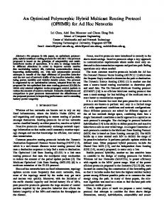
Fig. 1 shows an example of the network topology generated by the proposed clustering scheme. The network is composed of 26 nodes numbered from a to z. Four nodes (a, c, i, and u) are elected as CHs via two rounds of messages exchange (i.e., HELLO messages and ELECT_CH messages). Other nodes in the network settled in the state of ordinary or gateway. C. Proposed Cluster Mainenance Scheme As mentioned above, the clusterhead is responsible for maintaining local membership and global topology information. In order to maintain a cluster, each CH broadcasts the INTRA_CB messages at INTRA_CB_INTERVAL within the cluster periodically. When the corresponding replies arrive at the initiating CH, the CH updates the information in both the member node list and the neighbor cluster list which it maintains. In order to let each CH have knowledge of topology information of the whole network, an inter-cluster beacon (INTER_CB), including the information of CH’s member nodes and neighbor clusters, is propagated among CHs. At each INTRA_CB_INTERVAL, each CH will create an INTER_CB packet and unicast it to each of its neighbor CHs. Upon receiving an INTER_CB, a CH will relay the message to its neighbor CHs. Each CH maintains such cluster-level information in a table named as global cluster table (GCT). The GCT is organized into a structure of connected graph, in which each vertex represents a CH with a link to each of its neighbor CHs. The GCT produced by the CH in Fig. 1 is illustrated in Fig. 2.
Fig. 1. An example of a 2-hop clustered network for HCR
In our scheme, there are four possible states for nodes: undecided, clusterhead, ordinary, and gateway. We assume that each node in the network is assigned a unique ID. The proposed cluster formation algorithm works as follows. Initially, all nodes are in the state of undecided. Then each node broadcasts a HELLO message to have knowledge of its neighbor nodes, which can be used to calculate its degree d. Thus, each node will have its clusterhead priority (i.e., a double tuple (d, ID)) to compete the role of clusterhead. Then, each node broadcasts an ELECT_CH message with the double tuple within its 2-hop neighborhood. Upon receiving an ELECT_CH message, a node will check whether the initiating node has a clusterhead priority over itself. If so, the node then re-broadcasts the message to its neighbors. Otherwise, the node discards the message. If a node has not received any ELECT_CH with a higher clusterhead priority during another predetermined period of time, it will change its state to clusterhead (CH). Meanwhile, a clusterhead declaration message called intra-cluster beacon (INTRA_CB) is broadcast to all its 2-hop neighbors. When a node in the state of undecided receives an INTRA_CB, it goes to the state of ordinary. Similarly, if an ordinary node receives more than one INTRA_CB, it will become a gateway node. The information about host clusterheads is maintained in a host clusterhead list in each node. Joint gateways are those nodes that lie in separate clusters, but are within transmission range of one another.
Fig. 2. An example of global cluster table
Note that any CH is at least three hops away from other CHs immediately after the clusters are formed in the case where the cluster radius k is 2 as set. However, two CHs may come within two hops, which may trigger a clusterhead change event. Unfortunately, the moment that two CHs hear INTRA_CBs from each other may be frequent due to rapid node mobility in mobile ad hoc networks. Many clustering schemes, including the Least Cluster Change (LCC) algorithm in CGSR, have the requirement that when two clusterhead come within direct transmission range of one another (for one-hop clusters), one clusterhead must give up its role. The drawback to this approach is that it can result in further clusterhead changes within the network. The changes may result in a rippling effect [17]. In fact, clusterhead changes are expensive due to the changes in the routing paths which occur as a consequence. In networks where routes are recorded between clusterheads, headship changes result in routing changes, and hence may generate significant routing overhead as a consequence. To further reduce the influence due to clusterhead changes, we propose a scheme, in which the clusterhead change is more rigidly restricted than LCC. Instead of requiring a cluster change whenever two clusterheads come within 2-hop transmission range of one another, the only moment a
This full text paper was peer reviewed at the direction of IEEE Communications Society subject matter experts for publication in the IEEE ICC 2006 proceedings.
clusterhead change may occur is when all member nodes of the clusterhead become gateways. When a CH decides to give up its headship, it will broadcast a cluster dismissal beacon (DISMISSAL_CB) within its 2-hop transmission range. The DISMISSAL_CB is also immediately propagated to all other CHs via the same way as an INTER_CB, in order to inform all CHs of the event. When a gateway node receives a DISMISSAL_CB message from one of its host clusterheads, it updates the host clusterhead list and the state if necessary. In the case of clusterhead, the CH will update the corresponding information in its neighbor cluster list and global cluster table. III. HYBRID CLUSTER ROUTING PROTOCOL A. Overview To the best of our knowledge, most of the cluster-based routing algorithms tend to use proactive approaches within the cluster and reactive routing for inter-cluster routing. This may help the compromise between proactive and reactive routing strategies. However, this type of schemes may incur significant route delay and routing overhead in cases where a great majority of destination nodes locate outside the cluster of source nodes due to substantial route request messages flooding within the whole network. Our goal is to design a routing protocol that benefits both route delay and routing overhead. That means the route delay should be bearable and the number of control packets should be controllable as well. We prefer to maintain the knowledge of full network topology as in link state routing, but wish to avoid the inefficient flooding mechanisms. Therefore, we develop our routing protocol based on the clustering scheme described in the previous section. Since the network is organized into a two-tier structure for the purpose of routing, the proposed HCR protocol divides routing into two levels, i.e., inter-cluster routing and intra-cluster routing, respectively. Inter-cluster routing is on the higher level, which means a packet is routed cluster by cluster. On the other hand, intra-cluster routing is on the lower level, which means a packet is routed within a cluster node by node. As described in Section II, the inter-cluster level information is maintained by CHs via a proactive scheme. The intra-cluster level information, which is less stable than inter-cluster level information, is just acquired when needed. Similar to other routing protocols for MANETs, routing in HCR consists of two main procedures, including route discovery and route maintenance. These two procedures will be presented in more detail respectively in sub-section B and C. B. Route Discovery When a source node has data packets to send to some destination, it checks its route table to determine whether it has an active route to the destination. If not, the node must perform a route discovery procedure to acquire a route to the destination. In HCR, the route discovery consists of inter-cluster route discovery and intra-cluster route discovery. Inter-cluster route discovery is initiated by a node by sending out a cluster list request (CLREQ) via a unicast method to one of its host clusterheads. After a CH receives a CLREQ, it will send a cluster list reply (CLREP) back to the CLREQ initiator. When the source node receives a CLREP message, it checks
whether the message is valid. If so, the node will update the route information in its route table. Otherwise, the node will try to send another CLREQ for MAX_CLREQ times. Intra-cluster route discovery is initiated when a node desires to transmit a packet to an expected node that locates within the same cluster. In HCR, the intra-cluster route discovery is based on an on-demand method. When a node receives a route request (RREQ), it will verify whether it can reply to the RREQ. The following two cases are possible: the node is the requested node or gateway; and an intermediate node has a valid route in its local routing table. If one of above two cases occurs, the node will unicast a route reply (RREP) with the route information to the RREQ initiator. Otherwise, the RREQ is re-broadcast by the node. C. Data Transmission
Fig. 3. An example of route establishment and data transmission
When the CLREQ initiator receives a valid CLREP, the node will fill the cluster list into the corresponding field in data packet’s header. In this way, the actual packet is routed to a gateway or the destination via the route information acquired by RREP. When a qualified gateway node receives the packet, it will forward the packet to the next cluster along the cluster list. Thus, the packet is forwarded cluster by cluster until it arrives at the last gateway that locates within the same cluster as the destination node. Then, the packet will be forwarded to the destination node by node within the last cluster. Fig. 3 illustrates an example of route establishment and data transmission. D. Route Maintenance The cluster-level topology might change (e.g., cluster disconnected, or cluster mergence) due to node mobility. Thus, the cluster-level routing information either in the global routing table or in the header of data packets may become invalid. Route maintenance is the mechanism by which data packets can still be delivered to the destination in the case of changes in cluster-level routing information. In HCR, we propose a scheme named as global repair to salvage such packets and update invalid routing information. When the CH detects a route error in the cluster list, the CH will create a new cluster list, via the method described in inter-cluster routing section, for the intended destination. A cluster list error (CLERR) message, with the established
This full text paper was peer reviewed at the direction of IEEE Communications Society subject matter experts for publication in the IEEE ICC 2006 proceedings.
cluster list, is then unicast by the CH to the RREQ initiator. When the RREQ initiator receives the CLERR, it constructs a new complete cluster list using the newly established information in the CLERR and the original obsolete information on the packet. Meantime, the CLERR is forwarded to the source node which originates the packet to notify the change.
IV. PERFORMANCE EVALUATION AND ANALYSIS A. Simulation Enviroment and Parameters To evaluate the performance of HCR, we have implemented HCR in the simulator ns-2. All the scenarios have the similar node density. All nodes have the same transmission range of 250 meters, and are randomly placed within the simulation area. Random waypoint [18] model is selected as the mobility model, with the maximum mobility speed of 5 m/s and the same pause time of 30 seconds. The Distributed Coordination Function (DCF) with RTS/CTS of IEEE 802.11 for wireless LAN, with a channel bandwidth of 2 Mbps, is used as the MAC layer. Traffic sources are CBR (Constant Bit Rate), with the rate of 4 packets per second and the size of 512 bytes per packet. All simulations are run for 200 seconds. As for HCR, the values of three key parameters are set as follows: cluster radius k = 2, INTRA_CB_INTERVAL = 5 seconds, and INTER_CB_INTERVAL = 10 seconds. B. Evaluation Metrics We use three key metrics to evaluate the performance of routing protocols of MANETs: normalized routing overhead, packet acceptance ratio, and average end-to-end delay.
Fig. 4. An example of global repair scheme in HCR
An example of global repair scheme is shown in Fig. 4. Originally node s transmits data packets to node d via a cluster list {A, I, C}. However, cluster I and C become separated due to node mobility. Thus, the first situation described above may happen in clusterhead i. That is, clusterhead i may receive a RREQ request for a route to cluster C from node h. Then, a CLERR message with a new cluster list {I, U, C} is unicast by clusterhead i to node h. Upon receiving the CLERR, node h constructs a repaired cluster list {A, I, U, C}. Then cached packets intended to node d will be routed to cluster U rather than cluster C. Meanwhile, the CLERR message is forwarded to source node s. Node s will utilize the repaired cluster list for subsequent data packets intended to node d.
(a) Normalized Routing Overhead
C. Simulation Methodology and Simulation Results We select three well-known routing protocols for MANETs, including AODV, DSR, and CBRP to be compared with HCR. The overall goal of our experiments is to measure the performance of all selected routing protocols in their reactions to network size change and network traffic change. Different experiments are carried out with the results as follows. C.1 Adaptability to Network Scale Fig. 5. shows the results in terms of normalized routing overhead, packet acceptance ratio and average end-to-end delay, of each protocol under varying network scales, in which the average connections per nodes is 0.20.
(b) Packet Acceptance Ratio
(c) Average End-to-end Delay
Fig. 5. Performance in networks with varying scales, 5m/s node maximum speed, 30s pause time, and 0.20 average connections per nodes
As shown in Fig. 5(a), normalized routing overhead is increased with the increasing network size for all routing protocols. DSR outperforms the other three protocols for its absence of periodical control packets when the size of network is small. However, the overhead of HCR is the smallest when the number of nodes is more than 150. This is mainly contributed by the cluster maintenance schemes and routing
schemes utilized in HCR. The routing overhead for discovering inter-cluster routes and intra-cluster routes is restricted within a cluster rather than the whole network. Moreover, the established intra-cluster route information can be better re-utilized with the increasing connections in the network. Furthermore, the route repair scheme named as global repair produces less route maintenance overhead, for the cluster-level
This full text paper was peer reviewed at the direction of IEEE Communications Society subject matter experts for publication in the IEEE ICC 2006 proceedings.
route is more stable than pure node-level route used in AODV, DSR and CBRP. The detailed explanation and analysis of routing overhead will be described in sub-section D. As shown in Fig. 5(b), packet acceptance ratio of all selected protocols decreases with the increase of the number of nodes due to longer and more fragile routes from the source to the destination. When the network scale is small, DSR performs best owing to its efficient source routing scheme. The value of HCR is close to those of AODV and CBRP. However, when the network scale is large, the performance of HCR is the best due to its largely reduced routing overhead, efficient route discovery schemes and global repair scheme adopted. Fig. 5(c) shows the average end-to-end delay for each protocol under the conditions of varying network sizes. We can see all protocols incur longer delay with the increase in network size since a longer route may be required from the source to the destination. In a small network, AODV has slightly lower delay than the other three routing protocols, mainly because HELLO
(a) Normalized Routing Overhead
mechanism provides routes to neighbor nodes immediately. However, HCR performs the best of all when the network size is larger. As described above, the routing overhead of HCR is the least in a large-scale network. This might result in the least network congestion which, to some extend, affects the packet delay. Moreover, when a packet is routed cluster by cluster, significant delay can be reduced for there might be available intra-cluster route information established by previous packets. C.2 Adaptability to Traffic Load Fig. 6 shows the results of three metrics in a network under varying traffic load (here it is measured by connections), where the number of nodes is 200. The range of average connections per node is from 0.05 to 0.25. As illustrated in Fig. 6(a), the overhead of HCR is decreased, while those of the other three protocols are increased, with the
(b) Packet Acceptance Ratio
(c) Average End-to-end Delay
Fig. 6. Performance in a network with varying traffic load, 200 nodes in 2000 * 2000 m, 5m/s node maximum speed, and 30s pause time
increase of connections in the network. Such decrease in HCR is due to its cluster maintenance schemes and route discovery schemes. As described earlier, the cluster maintenance overhead is the fixed portion of the HCR’s routing overhead. When there are more connections, more routing is needed so that the proportion of cluster maintenance in the overall overhead becomes relatively smaller. Moreover, the intra-cluster route information can be more frequently re-utilized with the increasing connections since a packet is forwarded cluster by cluster in HCR. Thus, the less overhead will contribute to the higher packet acceptance, shown as in Fig. 6(b), and the lower average end-to-end delay, shown as in Fig. 6(c) respectively. The increase of delay in AODV, DSR and CBRP resulted from their larger number of network-wide route requests and increased significant route maintenance overhead, with the increase of connections in the network. D. Mathematical Analysis In this sub-section, we will compare the routing overhead between HCR and a generic on-demand routing protocol via an analytical method. Commonly, in a generic on-demand routing protocol, a route request is initiated from the source via a network-wide flooding when there is no available route. Each acquired route is associated with a maximum route lifetime. In order to compare HCR with such a generic on-demand routing protocol, INTER_CB_INTERVAL in HCR is set as the
maximum route lifetime, and INTRA_CB_INTERVAL is half of INTER_CB_INTERVAL. Assume that n nodes are uniformly distributed in the network, which is a two dimensional regular degree-4 grid as in [19]. Also, we assume that the cluster radius in HCR is k, and average connections per node is α. Here, we define the routing overhead as the total amount of routing protocol control packets in the network during each maximum route lifetime. As HCR is concerned, routing overhead is composed of three main parts: cluster maintenance overhead, route discovery overhead and route maintenance overhead. While in a generic on-demand routing protocol, the routing overhead only consists of later two types of overhead. Since route maintenance overhead due to route repair is a small portion of total routing overhead in both types of routing protocols, it is ignored in analyzing the routing overhead. Assume that Oh-cluster represents the cluster maintenance overhead of HCR, Oh-route represents the route discovery overhead of HCR, Oo-route the route discovery overhead of a generic on-demand routing protocol. As proofed in [19], the total number of nodes including the clusterhead in a cluster (with radius = k) is 2(k2 + k) + 1, and the number of gateway nodes is 4k. Since each gateway locates between just two clusters, the average number of nodes in a cluster is 2(k2 + k) + 1 - (4(k-1)/2 + 4/4) = 2k2. Then, the total number of clusters is n/2k2. HCR’s cluster maintenance
This full text paper was peer reviewed at the direction of IEEE Communications Society subject matter experts for publication in the IEEE ICC 2006 proceedings.
overhead Oh-cluster is made up of periodic INTRA_CBs, INTRA_CBREPs, and INTER_CBs. Where Oh-cluster = k n n ×2(k 2 + k)+1− 4k + 4∑i 2 + 2 × 2 −1× 2k 2k +1 2 k 2 k i =1
n
2
Oh-route = n × a × (2(k 2 + k ) + 1)× 2 n × (1 − β ) 2 2k
Extensive simulation results and theoretical analysis have shown that HCR has better scalability, robustness, and adaptability than several well-known routing protocols such as AODV, DSR and CBRP in large scale MANETs.
(1)1
ACKNOWLEDGEMENTS
(2)
This work was partially supported by NSFC (grants 6053310 and 60572060) and CAS under “Knowledge Innovation Project” (grant 20056310) and “100 Talents Program” (grant 20034020).
The variable β called as route reuse ratio is a function of (α, n, k), with the value of 0