IOP Conference Series: Earth and Environmental Science
PAPER • OPEN ACCESS
Effect Method Evaluation of Forecasting Scour by Propeller in Harbours To cite this article: P T Ghazvinei et al 2018 IOP Conf. Ser.: Earth Environ. Sci. 164 012016
View the article online for updates and enhancements.
This content was downloaded from IP address 139.81.78.101 on 21/06/2018 at 13:22
2018 2nd International Conference on Energy and Environmental Science IOP Publishing IOP Conf. Series: Earth and Environmental Science 164 (2018) doi:10.1088/1755-1315/164/1/012016 1234567890 ‘’“” 012016
Effect Method Evaluation of Forecasting Scour by Propeller in Harbours P T Ghazvinei1*, H H Darvishi1, S Soon2 1
Department of Civil Engineering, Technical and Engineering College, Ale Taha University, Tehran, Iran / Mailing address Ale Taha University, Koohsar Blv., Shahran, Tehran, Iran 2 Department of Civil Engineering, Faculty of Engineering, University of Malaya, 50603 Kuala Lumpur, Malaysia
[email protected] Abstract. The scour induced by a propeller wash is experimentally in uniform and nonuniform sand. A series of laboratory experiment with different experimental parameters was conducted in the current research. Moreover, the characteristics of scour hole were studied and compared including depth, length, and width between uniformly and non-uniformly distributed sand. Equations of predicting maximum scour depth, proposed by previous researchers, were evaluated using the current experimental data. Results revealed that there is a need to improve the study in propeller-induced seabed scour in non-uniform sand.
1. Introduction Ship’s propeller jet (commonly referred to as propeller wash) is the backwash produced by its rotating propeller, which is usually a high velocity flow used to propel a vessel [1]. Seabed without adequate protection system could be vulnerable to scouring from the wash, particularly in shallow and confined water [2]. Although most damage to structure occur at the flash stormy times, undermining the structure s’ foundations in a relatively long duration of time make the foundation weak for the final failure at the flash stormy times conditions [3]. Low under-keel clearances happen in harbour basins, where can cause severe scouring, and consequent jeopardize the structures in harbour by undermining its foundation. Consequently, this leads to the need for costly maintenance and repairing work [4]. A number of case studies relevant to the propulsion action of ships caused serious damage in various harbours and ports, which have been reported over the past three decades [2, 5-12]. The understanding of the extent of seabed scour due to propeller wash is essential to minimize the risk of failure of harbour structures. The interaction between propeller jet and the seabed was also described by Sumer [13] and Gaythwaite [14]. Research on propeller-induced seabed scour was initiated in an unconfined propeller jet. The influences of the rudder [15, 16], hull and the berth geometry to the velocity within the jet were included later on. Johnston, Hamill [15] investigated the scouring action in an unconfined propeller jet. Moreover, Hong, Wu [17] studied the time-dependent maximum scour depth induced by an unconfined jet where Ryan, Hamill [18] carried out an experimental investigation of scour in conjunction with quay walls in harbour using Artificial Neural Networks (ANNs). The review of the literature showed that existing experimental studies of propeller-induced seabed scour by previous
*
Corresponding author:
[email protected]
Content from this work may be used under the terms of the Creative Commons Attribution 3.0 licence. Any further distribution of this work must maintain attribution to the author(s) and the title of the work, journal citation and DOI. Published under licence by IOP Publishing Ltd 1
2018 2nd International Conference on Energy and Environmental Science IOP Publishing IOP Conf. Series: Earth and Environmental Science 164 (2018) doi:10.1088/1755-1315/164/1/012016 1234567890 ‘’“” 012016
researchers were conducted on uniformly-distributed non-cohesive sediments, where practically in ports area, sediments are non-uniformly-distributed. In addition, it was found that the amount of empirical data based on unreliable observations and simulating at the actual conditions of the scour were limited [19]. Non-cohesive sediments were used in the experiments to provide a suitable range of applicability, with one uniformly and one non-uniformly distributed sands. The characteristics of scour hole such as depth, length, and width between uniformly and non-uniformly distributed sand were observed through a series of the laboratory experiments in the current research. The outcomes improve the knowledge of the propeller-induced seabed scour in uniformly and specially in non-uniformlydistributed non-cohesive sediments. 2. Experimental setup The experiments were conducted in a 3 m × 1.2 m × 1 m deep rectangular acrylic tank to observe scour process. A three-bladed, fixed-pitched, open propeller was used to model the scour in the bed. Table 1 shows the propeller characteristics. Table 1. Propeller characteristics. Propeller Diameter (mm)
Hub Diameter Number (mm) of Blades
Coefficient of Thrust
Pitch ratio
Blade Ratio
Area Rudder Angle
220
80
0.4
1
0.45
0
3
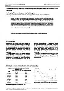
To neglect scaling effects of the viscosity, values of the flow and propeller Reynolds Numbers were designed to be larger than 3×10³ and 7×10⁴. Two types of non-cohesive sediments were applied in the experimentations to make available reliable range of applicability, in both uniform (d50 = 0.9 mm) and non-uniform (d50 = 0.75 mm) distribution of the sands with geometric standard deviations equal to 1.4 and 2 for uniform and non-uniform sediments, respectively. Figure 1 shows the schematic layout of the experimental setup. The sediments of 2.1 m long × 1.2 m wide × 0.2 m deep was laid flat in the water tank. The propeller was turn on with two different speed 350 and 500 rpm, for each series of experiments. Propeller was turned off at time = 0.5, 1, 2, 4, 8, 16, 32, 64, and 128 hours after the commencement of each test without any disturbance. Scour depth was measured using digital point gauge on a 100 mm x 100 mm grid, with depth measure along the scour hole. 3. Methods The evolution of scouring profile along the longitudinal direction (downstream of the propeller) of the current study showed similarity and good agreement to Hong et al. (2013)’s experiments resulted a small scour hole lower than the propeller, meanwhile a deposition downstream was next to the primary scour hole within the existence of four stages of scouring process. A primary scour and deposition with ripples occurred downstream of the scour hole was observed downstream side of the propeller. The size of main scour hole increased with the increasing time during developing stage. A small scour hole is formed below the propeller as the propeller drains fluid from behind the propeller. The experiments were continued and ended after 128 hours to ensure an asymptotic condition.
Figure 1. Side view layout of experimental setup. 4. Results and discussion 2
2018 2nd International Conference on Energy and Environmental Science IOP Publishing IOP Conf. Series: Earth and Environmental Science 164 (2018) doi:10.1088/1755-1315/164/1/012016 1234567890 ‘’“” 012016
4.1 Scour profiles under asymptotic condition Figure 2 compares the asymptotic dimensional scour profile induced by propeller in uniformlydistributed and non-uniformly distributed sand for the experiments within different offset height and rotational speed. It was found that the scour hole prompted by propeller in uniform sand is deeper than the one in non-uniform sand with the similar clearance and rotational speed. Furthermore, deposition formed in uniform sand was slightly thicker than non-uniform.
Figure 2. Typical scour profiles induced by propeller jet in uniform sand (a) 500rpm, 0.5Dp (b) 500rpm, 1Dp (c) 350rpm, 0.5Dp (d) 350rpm, 1Dp; typical scour profiles induced by propeller jet in non-uniform sand at four different stages for: (e) 500rpm, 0.5Dp (f) 500rpm, 1Dp (g) 350rpm, 0.5Dp (h) 350rpm, 1Dp. 4.2 Evaluating the existing methods in prediction maximum scour depth Ryan and Hamill (2011) suggested an equations to calculate the erosion depth in a combined existence of berth structures and a rudder. The equation was offered εmax as the maximum scour depth for the associated Ω and Г parameters as below: Ω ln (1) Table 2 shows the range of applicable and current experimental parameters using the above equations. Compare with the current experimental characteristics, equations. (1) to (3) are not suitable to be used in the current experiments. Furthermore, Hong et al. (2013) suggested a semi-empirical equation to
3
2018 2nd International Conference on Energy and Environmental Science IOP Publishing IOP Conf. Series: Earth and Environmental Science 164 (2018) doi:10.1088/1755-1315/164/1/012016 1234567890 ‘’“” 012016
predict the time-dependent maximum depth of the scour. The dimensionless equation for the estimation of time-dependent scour depth induced by a propeller wash was: ,
0.014 1.882 2.477
(2)
.
. . .
.
. .
(3)
.
(4)
.
(5)
where, ds,t is the time-dependent maximum scour depth, Uo is the efflux velocity of propeller jet. Table 2. Range of experimental parameters Range of applicable Range of current experimental parameters experimental parameters Fo
4.87 - 11.20
11.72 - 16.74
C/d50
19.40 - 85.53
Dp/d50
39.10 - 172.37
122.22 - 293.33 244.44 - 293.33
Yw/Dp
1.52 - 3.05
2.73
α
0 to -35 ̊
0̊
The proposed equations were demonstrated to be valid with good accuracy for scour data in uniform sand, in which the measured scour depth and predicted scour depth were mostly in the zone of acceptable agreement (less than 10% differences compared with the line of perfect agreement). While in non-uniform sand, the difference between the measured and predicted scour depth were almost out of the zone of acceptable agreement (exceeded 10% differences compared with the line of perfect agreement). Figure 3 compares the measured and predicted depth of maximum scour proposed by equation (2) with the line of perfect agreement in both uniformly-distributed and non-uniformly distributed sand. The figure shows that maximum scour depth predicted in non-uniformly distributed sand using equation (2) is deeper than uniformly distributed sand, which contradict to the experimental results. The measured data showed that scour depths induced by propeller wash were deeper in uniform sand, while using the published equation, the scour depths were deeper in non-uniform sand as shown in the figure 3. This implies that the equation (2) has over predicted the maximum scour depth in non-uniform sand. A more accurate equation is therefore needed to improve the study of propeller-induced scour in non-uniform sand.
4
2018 2nd International Conference on Energy and Environmental Science IOP Publishing IOP Conf. Series: Earth and Environmental Science 164 (2018) doi:10.1088/1755-1315/164/1/012016 1234567890 ‘’“” 012016
Figure 3. The measured and predicted depth of maximum scour proposed by equation (4) with the line of perfect agreement in both uniformly-distributed and non-uniformly distributed sand. 5. Conclusions Experiments on ship’s propeller jet-induced seabed scour in uniform and non-uniform sands with two different propeller clearance and two different propeller rotational speeds were conducted. The evolution of scouring profile downstream of the propeller showed a similarity to the previous published results of the literatures. There is a small scour hole below the propeller, a primary scour hole downstream that was followed by deposition. Recent equations of predicting the time-dependent maximum scour depth proposed by Hong, Wu [17] was used in the current study. While these proposed equations have been demonstrated to be applicable with good accuracy with less than 10% differences for predicting scour depth in uniform sand, there has been considerable uncertainty and over prediction when using these equations to predict scour in non-uniformly sand. Therefore, more series of laboratory test in propeller-induced scour in non-uniform sand is conducted to enhance the existing predictive methods of the maximum scour. 6. References [1]. Demirbilek, Z., "Review of Hydrodynamics of High-Speed Marine Vehicles by Odd M. Faltinsen: Cambridge University Press, New York, 2006. Price: $100.00. pp. 454". 2006, American Society of Civil Engineers. [2]. Evans, G., "Seabed Protection Systems to prevent Scour from High-Speed Ships", No. (2010), [3]. Ghazvinei, P.T., et al., "Assessment of local scour at bridges abutment", Research Journal of Applied Sciences, Engineering and Technology, 8, No. 3, (2014), p. 296-304. [4]. Hashmi, H.N., "Erosion of a granular bed at a quay wall by a ship's screw wash", No. (1995), [5]. Bergh, H. and K. Cederwall, Propeller erosion in harbours. Hydraulics Laboratory, Royal Institute of Technology Stockholm, Sweden; 1981. [6]. Bergh, H. and N. Magnusson, "Propeller erosion and protection methods used in ferry terminals in the port of Stockholm. Bulletin PIANC 58", No. (1987), [7]. Brewster, P., et al. "A CFD model of a marine propeller wash". in The Seventh International Offshore and Polar Engineering Conference. International Society of Offshore and Polar Engineers, (1997), p. [8]. Chait, S., "Undermining of quay walls at South African ports due to the use of bow thrusters and other propeller units", No. (1987), [9]. Longe, J., P. Hebert, and R. Byl, "Erosion problems at existing quay constructions due to bow thrusters and main propellers of ships when berthing or leaving", Bulletin of the Permanent International Association of Navigation Congresses [PIANC], No. 58, (1987), [10]. McKillen, H.G., A Model and Field Study of Ship Propulsion Induced Bed Movements at Berths. Queen's University of Belfast; 1985. [11]. Robakiewicz, M., "Bottom erosion as an effect of ship propeller action near the harbour quays", Bulletin of the Permanent International Association of Navigation Congresses [PIANC], No. 58, (1987), [12]. Verhey, H., T. Blokland, and M. Bogaerts, "Experiences in the Netherlands with quay structures subjected to velocities created by bow thrusters and main propellers of mooring and unmooring ships", Bulletin of the Permanent International Association of Navigation Congresses [PIANC], No. 58, (1987), [13]. Sumer, B.M., The mechanics of scour in the marine environment. World Scientific; 2002. [14]. Gaythwaite, J.W., "Design of Marine Facilities for Berthing", Mooring and Repair of, No. (2004), [15]. Johnston, H.T., et al., "Influence of a boundary on the development of a propeller wash", Ocean Engineering, 61, No. (2013), p. 50-55. [16]. Svedman, C., et al., "Plasma proteins in a standardised skin mini-erosion (I): permeability changes as a function of time", BMC dermatology, 2, No. 1, (2002), p. 3. [17]. Hong, S., et al., "Microstructure and cavitation–silt erosion behavior of high-velocity oxygen– fuel (HVOF) sprayed Cr 3 C 2–NiCr coating", Surface and Coatings Technology, 225, No. (2013), p. 85-91. 5
2018 2nd International Conference on Energy and Environmental Science IOP Publishing IOP Conf. Series: Earth and Environmental Science 164 (2018) doi:10.1088/1755-1315/164/1/012016 1234567890 ‘’“” 012016
[18]. Ryan, D., G.A. Hamill, and H.T. Johnston, "Determining propeller induced erosion alongside quay walls in harbours using Artificial Neural Networks", Ocean Engineering, 59, No. (2013), p. 142-151. [19]. Ghazvinei, P.T., et al. "Contraction scour analysis at protruding bridge abutments". in Proceedings of the Institution of Civil Engineers-Bridge Engineering. Thomas Telford Ltd, (2015), p. 39-53.
6