metals Article
Effect of Ausforming Temperature on the Microstructure of G91 Steel Javier Vivas *, Carlos Capdevila, José Antonio Jimenez, Miguel Benito-Alfonso and David San-Martin Centro Nacional de Investigaciones Metalúrgicas (CENIM), Consejo Superior Investigaciones Científicas (CSIC), Avda Gregorio del Amo, 8, E 28040 Madrid, Spain;
[email protected] (C.C.);
[email protected] (J.A.J.);
[email protected] (M.B.-A.);
[email protected] (D.S.-M.) * Correspondence:
[email protected]; Tel.: +34-91-553-89-00; Fax: +34-91-534-74-25 Received: 18 May 2017; Accepted: 23 June 2017; Published: 27 June 2017
Abstract: The development of thermomechanical treatments (TMT) has a high potential for improving creep-strength in 9Cr-1Mo ferritic/martensitic steel (ASTM T/P91) to operate at temperatures beyond 600 ◦ C. To maximize the number of nanoscale MX precipitates, an ausforming procedure has been used to increase the number of nucleation sites for precipitation inside the martensite lath. Relative to standard heat treatments (consisting of austenitization at about 1040 ◦ C followed by tempering at about 730 ◦ C) this processing concept has enabled achieving a microstructure containing approximately three orders of magnitude higher number density of MX precipitates having a size around four times smaller in ASTM T/P91 steel. On the other hand; this TMT has little effect on the size and number density of M23 C6 particles. The optimized microstructure produced by this TMT route proposed is expected to improve the creep strength of this steel. Keywords: creep resistant steels; carbonitrides precipitation; martensite; thermomechanical treatment; ferritic/martensitic steel; MX nanoprecipitates
tempering;
1. Introduction The 9-12Cr Ferritic/martensitic (FM) steels are widely used in power generating and petrochemical plants for operating temperatures up to 620 ◦ C because of their excellent combination of creep strength, thermal properties, and oxidation resistance as well as acceptable room temperature mechanical properties and also good weldability [1]. In the designs of advanced power plant components for future fission and fusion power plants, which will operate at temperatures up to 650 ◦ C, the primary emphasis was placed on the development of new steel grades with superior long-term creep and thermal fatigue properties [2,3]. Several promising ferritic steels have been developed by the addition of very expensive alloying elements such as W and Co [4–7]. However, there are economic and technical advantages for using the same basic composition of ASTM T/P 91 (here after named G91) and considerably raising creep-strength of this material by the development of thermomechanical treatments (TMT) [8–11]. The creep resistance of a G91 steel results from the combination of several types of barriers to dislocation motion: a high density of martensitic lath boundaries, solid solution strengthening with elements with much larger atomic size than iron, and fine dispersion of second phase particles [12,13]. Although the overall creep strain rate is the result of the combined effects of these mechanisms, it has been reported in previous works that the creep strength is mainly increased by the precipitation of fine MX carbonitrides in the matrix [14,15], which are very effective barriers to pin dislocations, and very stable during long-term aging [16–18]. The goal of this paper is to develop a processing route to improve the creep strength of a conventional G91 steel. Prior to the optimization of TMT, thermodynamic calculations using ThermoCalc® will be carried out to foresee the most promising microstructures. In order to maximize Metals 2017, 7, 236; doi:10.3390/met7070236
www.mdpi.com/journal/metals
Metals 2017, 7, 236
2 of 11
The goal of this paper is to develop a processing route to improve the creep strength of a Metals 2017, 7, 236 2 of 11 conventional G91 steel. Prior to the optimization of TMT, thermodynamic calculations using ThermoCalc® will be carried out to foresee the most promising microstructures. In order to maximize theofnumber of nanoscale MX precipitates, an ausforming will be to applied to the number nanoscale MX precipitates, an ausforming procedureprocedure will be applied increase increase the of number of nucleation sites for precipitation inside thelath martensite lath relativeheat to the number nucleation sites for precipitation inside the martensite relative to standard standard heat treatments. Previous works havethe investigated the effect of applying instead of treatments. Previous works have investigated effect of applying a TMT instead aofTMT a conventional aheat conventional heat treatmentthe demonstrating improvement creep strength achieved with of a treatment demonstrating improvementthe in creep strength in achieved with a finer dispersion finer dispersion MXtries [8,9,11]. This work tries to deepen oureffect understanding of the effect of the MX [8,9,11]. Thisof work to deepen our understanding of the of the ausforming temperature ausforming temperature onmicrostructure the temperedinmartensitic microstructure in order to quantifyin the on the tempered martensitic order to quantify the importance of ausforming the importance of ausforming the TMTThe to optimize theachieved creep strength. achieved in TMT to optimize the creepin strength. conclusions in this The workconclusions will allow us to clarify this work will allow us to clarify what processing parameters affect the heterogeneous formation of what processing parameters affect the heterogeneous formation of thermally stable precipitates. thermally stable precipitates. 2. Materials and Methods 2. Materials and Methods A commercial G91 FM steel supplied by CIEMAT (Madrid, Spain) in the form of a plate was usedAincommercial this work. The this steelSpain) is given material G91nominal FM steelchemical suppliedcomposition by CIEMATof(Madrid, in in theTable form1.ofThis a plate was ◦ was received after The a heat treatment consisting of normalization 30 min followed by used in this work. nominal chemical composition of this steelatis1040 givenCinfor Table 1. This material ◦ C for 1 h, both with air cooling to room temperature. tempering at 730 was received after a heat treatment consisting of normalization at 1040 °C for 30 min followed by tempering at 730 °C for 1 h, both with air cooling to room temperature. Table 1. Nominal composition in wt % of Grade 91 ferritic/martensitic steel.
Table 1. Nominal composition in wt % of Grade 91 ferritic/martensitic steel. Elements C Si Mn Cr Mo V Nb N Wt %
Elements C 0.1 0.4 Wt %. 0.1
Si Mn Cr 0.4 9.0 0.4 0.4 9.0
Mo V Nb 1.0 0.2 1.0 0.2 0.07
N 0.07 0.038
Fe 0.038 balance
Fe balance
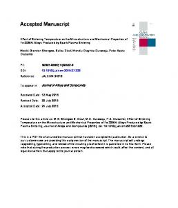
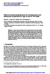
Thermodynamic calculations, calculations, used used as as guidelines guidelines to to select select the the temperatures temperatures for for the the Thermodynamic ® (Solna, Sweden) Thermomechanical Treatment (TMT), were performed with the Thermo-Calc ® Thermomechanical Treatment (TMT), were performed with the Thermo-Calc (Solna, Sweden ) software based based on on the the CALPHAD CALPHAD (Computer (Computer Coupling Coupling of of Phase Phase Diagrams Diagrams and and Thermo-chemistry) Thermo-chemistry) software using the the database database TCFE8. TCFE8. The The new new TMT TMT approach approach proposed proposed in in this this work work is is shown shown schematically schematically in in using Figure 1. Cylindrical samples with 10 mm length × 5 mm diameter were given 20% deformation at Figure 1. Cylindrical samples with 10 mm length × 5 mm diameter were given 20% deformation at − 1 0.1 ss−1 inina aBähr BährDIL DIL805A/D 805A/Dplastodilatometer plastodilatometer(TA (TAInstruments, Instruments,New NewCastle, Castle,DE, DE,USA). USA). The The samples samples 0.1 ◦ C/s and cooled at 50 ◦ C/s. were heated at 5 were heated at 5 °C/s and cooled at 50 °C/s.
Figure 1. Thermomechanical Treatment (TMT) scheme. Figure 1. Thermomechanical Treatment (TMT) scheme.
The microstructure of as-received material and material after TMT simulation treatments was The microstructure of as-received material andgun material afterelectron TMT simulation treatments was analyzed using optical microscopy, field emission scanning microscopy (FEG-SEM), analyzed using optical microscopy, field emission gundiffraction scanning electron (FEG-SEM), orientation maps obtained by electron backscatter (EBSD),microscopy transmission electron orientation (TEM), maps obtained by electron backscatter diffractiongrinding (EBSD), and transmission microcopy microcopy and X-ray diffraction (XRD). Standard polishingelectron procedures were (TEM), and X-ray diffraction (XRD). Standard grinding and polishing procedures were used for sample used for sample preparation, which included a final polish with 1 micron diamond paste. Polished preparation, which included a final polish with 1 micron diamond paste. Polished specimens were
Metals 2017, 7, 236
3 of 11
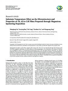
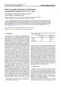
etched with a solution of 5 mL hydrochloric acid, 1 g of picric acid and 100 mL of ethyl alcohol (Vilella’s reagent) to develop the microstructural features. EBSD measurements were performed with a JEOL JSM 6500 FEG-SEM (JEOL Ltd., Tokyo, Japan) operating at 20 kV equipped with a fully automatic EBSD attachment from Oxford Instruments HKL (Abingdon, UK). Residual damage in EBSD samples from diamond polishing was removed through an additional polishing stage with colloidal (40 nm). EBSD mapping has been carried out on an area of about 900 × 400 µm2 at step sizes of 0.4 µm. The HKL Channel 5 software (Oxford Instruments, Abingdon, UK) has been used for data processing in order to obtain a graphical representation of the microstructure by marking the sample points of the grains in a map using colors specific to the lattice orientation. Observation of precipitates present in the microstructure was performed on thin foils by TEM in a JEOL JEM 2100 and a JEOL JEM 3000F (JEOL Ltd., Tokyo, Japan). For this goal, disks 3 mm in diameter and 100 µm in thickness were cut. The thickness of these slices were further mechanically thinned and, afterwards, twin-jet electropolishing was performed at 25 ◦ C and 40 V using an electrolyte compose of 95% acetic acid and 5% percloric acid. XRD studies were carried out with Co-Kα radiation in a Bruker AXS D8 diffractometer equipped with Goebel mirror optics and a LynxEye Linear Position Sensitive Detector for ultra-fast XRD measurements. For the Rietveld refinement of the diffractograms, the version 4.2 program TOPAS (4.2, Bruker AXS, Billerica, MA, USA) has been used and the crystallographic information of the phases used was obtained from Pearson’s Crystal Structure Database for Inorganic Compounds, Release 2015/2016. Materials Park: ASM International, 2015. Line broadening due to the crystallite size and lattice strain was analyzed using the double-Voigt approach. It was concluded from this analysis that line broadening is mainly due to the microstrain produced by dislocations and their associated stress fields. Finally, Vickers hardness measurements were performed with a load of 5 kg on the longitudinal section of warm/hot compressed material before and after tempering. 3. Results and Discussion 3.1. Thermodynamic Calculations The equilibrium phase mole fraction of the coexisting phases in the microstructure of the G91 FM steel is shown in Figure 2 as a function of temperature. According to this figure, M23 C6 carbides will dissolve during the conventional austenitizing treatment at 1040 ◦ C, remaining undissolved about 1.59 × 10⁻³ mole fraction of MX precipitates. In order to improve the creep strength during the service life, it is necessary to maximize the amount of MX carbides finely dispersed that precipitate during the TMT. This point emphasizes the importance of increasing the austenitizing temperature to guarantee the dissolution of most MX precipitates present in the as-received microstructure. However, this treatment must be performed in the fully austenite region to avoid the presence of δ-ferrite, which is generally regarded as detrimental for creep properties [19]. Since δ-ferrite forms above 1255 ◦ C, according to Figure 2, an austenitizing temperature of 1225 ◦ C was selected. At this temperature, 5 min treatment was enough to get a complete homogenization of the microstructure due to the small size of the sample used. The effect of increasing the austenitizing temperature on the precipitation reactions during tempering was evaluated using Thermo-Calc® . The volume fraction of MX carbides (with M = Nb, V and X = C, N) present in the austenite decreases from 1.32 × 10⁻³ to 1.01 × 10⁻⁴ when the temperature is increased from 1040 to 1225 ◦ C. Therefore, more Nb/V/C/N will be available in solid solution in the austenite at 1225 ◦ C, compared to 1040 ◦ C, to precipitate during the subsequent tempering step. Thus, as some MX precipitates will still remain undissolved after austenitizing, the composition (of the martensite) prior to the calculation at the tempering step has to be corrected. These calculations show an increase in the volume fraction of MX precipitates during tempering at 740 ◦ C from 1.42 × 10⁻³ to 2.67 × 10⁻³ when the austenitizing temperature is increased from 1040
Metals 2017, 7, 236
4 of 11
Metals 2017, ◦ 7, 236
4 of 11
to 1225 C (two times greater). It should be kept in mind when comparing these calculations to the Metals 2017, 7, 236 4 of 11 the experimental that the authors assumed quasi-equilibrium been reached during calculations toresults the experimental results that thethat authors assumed thathas quasi-equilibrium has been austenitizing and tempering stepsand investigated in this work. reached during tempering investigated in this work. calculations to the the austenitizing experimental results that the steps authors assumed that quasi-equilibrium has been reached during the austenitizing and tempering steps investigated in this work.
Figure 2. Temperature evolution of phase mole fraction in G91 calculated by ThermoCalc. Figure2.2.Temperature Temperature evolution evolution of byby ThermoCalc. Figure of phase phasemole molefraction fractionininG91 G91calculated calculated ThermoCalc.
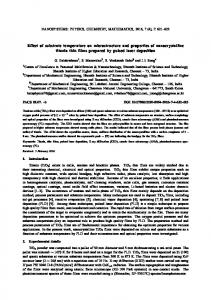
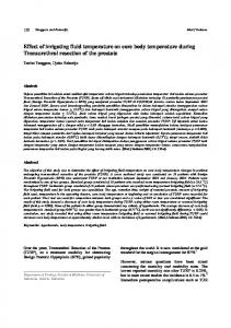
3.2. 3.2.Microstructural MicrostructuralCharacterization Characterization 3.2. Microstructural Characterization As the Figure 3a, 3a, as-receivedG91 G91 steelpresents presents a tempered martensite Asshown shownin themicrograph micrograph of of Figure a tempered martensite As shown ininthe micrograph of Figure 3a,as-received as-received G91steel steel presents a tempered martensite microstructure, with grain and lath boundaries decorated by tiny bright spots corresponding microstructure, with grain and lath boundaries decorated by tiny bright spots corresponding to to microstructure, with grain and lath boundaries decorated by tiny bright spots corresponding to M23 C6 MM 23C tempering. Quantitative Quantitativemetallography metallographystudies studies revealed 236 C6particles particles precipitated precipitated during during tempering. revealed an an particles precipitated during tempering. Quantitative metallography studies revealed an average lath average to 0.5 0.5 µm µm [20]. [20].Examination Examinationofofthis thismicrostructure microstructure at higher averagelath lathsize sizeranging ranging from from 0.25 to at higher size ranging from 0.25 to 0.5 µm [20]. Examination of this microstructure at higher magnifications with magnifications presenceof ofMX MXprecipitates, precipitates,distributed distributed matrix within magnificationswith withaaTEM TEM reveals reveals the presence in in thethe matrix within a TEM reveals the presence of MX precipitates, distributed in the matrix within the lath, in addition to the only on onboundaries. boundaries.As Asshown shown Figure 3b,c, thelath, lath,ininaddition additionto to M M2323C C66,, distributed distributed only inin Figure 3b,c, thethe sizesize of of Mthese , distributed only on boundaries. As shown in Figure6 3b,c, the size offrom these precipitates ranges 23 C6precipitates precipitates ranges ranges from from 100 to 200 to to 50 50 nmnm for for these 200 nm nm for for MM2323CC 6carbides carbidesand and from20 20 from 100 to 200 nm for M23 C6 carbides and from 20 to 50 nm for MX precipitates. MXprecipitates. precipitates. MX
(a) (a)
(b)
(b)
(c)
(c)
Figure 3. Microstructure of G91 after conventional heat treatment showing M23C6 precipitates (a) on Figure 3. 3. Microstructure MicrostructureofofG91 G91after afterconventional conventionalheat heattreatment treatment showing MC236 C (a) 6 precipitates Figure showing M23 precipitates (a) on grain boundaries (Scanning electron microscopy (SEM) micrograph) and (b) on lath boundaries on grain boundaries (Scanning electron microscopy (SEM) micrograph) and (b) on lath boundaries grain boundaries (Scanning electron microscopy (SEM) micrograph) and (TEM (b) onmicrograph). lath boundaries (Transmission electron microcopy (TEM) micrograph) and (c) MX within laths (Transmission (Transmission electron electron microcopy microcopy (TEM) (TEM) micrograph) micrograph)and and(c) (c)MX MXwithin withinlaths laths(TEM (TEMmicrograph). micrograph).
SEM examination showed that, during the austenitizing treatment at 1225 °C, all carbides were ◦°C, SEM examination showed that, during the austenitizing at 1225 C,4).all carbides were dissolved except for a negligible volume fraction of Nb rich MXtreatment precipitates (Figure dissolved except for a negligible volume fraction of Nb rich MX precipitates precipitates (Figure (Figure 4). 4).
Metals 2017, 7, 236 Metals 2017, 7, 236 Metals 2017, 7, 236
5 of 11 5 of 11 5 of 11
Figure austenitizing treatment treatment at at 1225 1225 ◦°C. Figure 4. 4. SEM SEM micrographs micrographs showing showing Nb Nb rich rich MX MX precipitate precipitate after after austenitizing C. Figure 4. SEM micrographs showing Nb rich MX precipitate after austenitizing treatment at 1225 °C.
The XRD pattern obtained in a sample quenched to room temperature after the austenitization The XRD pattern obtained in a sample quenched to room temperature after the austenitization Theonly XRDthe pattern obtained in aof sample to No room temperature afterwas thedetected austenitization showed diffraction peaks ferritequenched (Figure 5). retained austenite in the showed only the diffraction peaks of ferrite (Figure 5). No retained austenite was detected in the showed only the diffraction peaks of ferrite (Figure 5). No retained austenite was detected in the microstructure by this technique after the austenitization heat treatment. microstructure by this technique after the austenitization heat treatment. microstructure by this technique after the austenitization heat treatment.
Figure 5. X-ray diffraction pattern after austenitizing at 1225 °C. BCC stands for body-centered Figureferrite. 5. X-ray diffraction pattern after austenitizing at 1225 °C. BCC stands for body-centered cubic Figure 5. X-ray diffraction pattern after austenitizing at 1225 ◦ C. BCC stands for body-centered cubic ferrite. cubic ferrite.
Comparing the average prior austenite grain size present in as-received material (43 µm) and average priorµm), austenite grain size in as-received material (43 µm) and after Comparing austenitizingthe at 1225 °C (259 it is observed thatpresent a considerable grain growth occurs (Figure Comparing the average prior austenite grain size present in as-received material (43 µm) and after after 1225formed °C (259after µm),austenitizing it is observedatthat a considerable grain growth occurs (Figure 6). Noaustenitizing δ-ferrite hasatbeen 1225 °C. The inhibition of the austenite grain ◦ C (259 µm), it is observed that a considerable grain growth occurs (Figure 6). austenitizing at 1225 6). No δ-ferrite has been formed after austenitizing at 1225 °C. The inhibition of the austenite grain growth during austenitizing is related to the presence of fine second phase particles, dispersed in the ◦ C. The inhibition of the austenite grain No δ-ferrite has been formed after austenitizing at 1225 growth during austenitizing is related to the presence of fine second phase particles, dispersed in the microstructure, that pin the grain boundaries and restrain their movement. The explosive growth growth during austenitizing is related to the presence of fine second phase particles, dispersed microstructure, thatthat pin around the grain boundaries restrain their movement. The explosive growth observed indicates 1225 °C most and of the MX and M23 C6 precipitates are dissolved. In in the microstructure, that pin the grain boundaries and restrain their movement. The explosive observed indicates that around 1225 °C most of the MX and M 23 C 6 precipitates are dissolved. general, a coarse-grained microstructure presents better creep properties. High-temperature creep In is ◦ C most of the MX and M C precipitates are dissolved. growth indicates that around 23 6High-temperature general,observed a coarse-grained microstructure presents better creep creep is controlled by diffusion, and thus creep1225 strength increases withproperties. a decreasing the amount of regions In general, adiffusion coarse-grained microstructure presents better creep creep controlled diffusion, thus creep strength increases with aproperties. decreasingHigh-temperature the amount of regions with a highby rateand like grain boundaries. is controlled by diffusion, thus creep strength increases with a decreasing the amount of regions with a high diffusion rate and like grain boundaries. with a high diffusion rate like grain boundaries.
Metals 2017, 7, 236
6 of 11
Metals 2017, 7, 236 Metals 2017, 7, 236
6 of 11 6 of 11
(a) (a)
(b) (b)
Figure 6. 6. Optical austenite grain grain microstructure microstructure in in G91: G91: (a) after Figure Optical micrographs micrographs showing showing the the prior prior austenite (a) after Figure 6. Optical micrographs showing the prior austenite grain microstructure in G91: (a) after conventional heat heat treatment treatment and and (b) (b) after after austenitizing austenitizing at at 1225 1225 ◦°C. conventional C. conventional heat treatment and (b) after austenitizing at 1225 °C.
To maximize the number of nanoscale MX precipitates, a thermomechanical procedure was maximize the of nanoscale MX MX precipitates, a thermomechanical procedure was used to thenumber number ofdensity nanoscale precipitates, a the thermomechanical procedure usedTo to maximize increase the dislocation in the steel, increasing number of nucleation siteswas for increase the dislocation density indensity the steel, increasing the numberthe of nucleation sites for precipitation used to increase the dislocation in the steel, increasing number of nucleation sites for precipitation inside the martensite laths during the subsequent tempering◦ stage at 740 °C. After inside the martensite laths during the subsequent stage at 740 stage C. After austenitizing precipitation inside laths during thetempering subsequent tempering at in 740 °C. After austenitizing at 1225the °C, martensite samples were cooled to either 900 or 600 °C and hot-worked a controlled ◦ ◦ at 1225 C, samples were cooledwere to either 900 or 600 900 C and hot-worked in a controlled manner. austenitizing at 1225 °C, samples cooled to either or 600 °C and hot-worked in a controlled manner. Hot deformation 900 °C results in dynamic recrystallization (DRX) as can be seen in ◦ Catresults Hot deformation at 900 in dynamic recrystallization (DRX) as can be seen in Figure 7, manner. deformation at 900 °C from results dynamic recrystallization (DRX) as can be µm. seenOn in Figure 7, Hot leading to grain refinement, 259inµm for austenitized at◦1225 °C material to 141 leading7,to grain to refinement, from 259 µm259 for µm austenitized at 1225at 1225 C material to 141 On On the Figure grain refinement, from for austenitized °C material toµm. 141 the otherleading hand, as the transformation of austenite to ferrite at◦600 °C would take place afterµm. a long other hand, as the transformation of austenite to ferrite at 600 C would take place after after a longa time, the other hand, as the transformation of austenite to ferrite at 600 °C would take place long time, metastable austenite can be plastically deformed at this temperature without inducing this metastable austenite can becan plastically deformed at thisattemperature without inducing this phase time, austenite be plastically deformed this temperature without inducing this phasemetastable transformation. In this case, the low ausforming temperature and high strain rate would transformation. In this case, thecase, low ausforming temperature and high strain rate would suggest that phase transformation. In this the low ausforming temperature and high strain rate would suggest that neither recrystallization nor recovery of the microstructure is taking place and, thus, a neither recrystallization nor recoverynor of the microstructure is taking place and, thus, a more refined suggest that neither recrystallization recovery of the microstructure more refined martensitic structure in the quenched samples is expected. is taking place and, thus, a martensitic structure in the quenched samples is expected. more refined martensitic structure in the quenched samples is expected.
Figure 7. Optical micrographs showing the prior austenite grain microstructure in G91 after Figure 7. Optical micrographs showing the prior austenite grain microstructure in G91 after ausfroming at 900micrographs °C. Figure 7. Optical showing the prior austenite grain microstructure in G91 after ausfroming ausfroming at 900 °C. at 900 ◦ C.
EBSD investigations revealed a significant difference in the substructure of the samples EBSD investigations revealed a significant difference in the substructure of the samples ausformed at 600 and 900 °C, asashown in Figure 8a,b,inrespectively. While samples deformed at EBSD investigations revealed significant difference the substructure of the samples ausformed ausformed at 600 and 900 °C, as shown in Figure 8a,b, respectively. While samples deformed at ◦ ◦ 900600 °Cand showed typical martensite of blocks 8b), this lath-like at 900 the C, as shownlath in Figure 8a,b,structure respectively. While(Figure samples deformed at 900morphology C showed 900 °C showed theattypical lath martensite structure of blocks (Figureto8b), this lath-like morphology after deformation 600 °C is blurred (Figure 8a). This is attributed the higher number density of the typical lath martensite structure of blocks (Figure 8b), this lath-like morphology after deformation after deformation at 600 during °C is blurred (Figure 8a).ofThis is attributed to the higher number density of ◦ dislocations introduced the deformation austenite at 600 °C, which hindered typical block at 600 C is blurred (Figure 8a). This is attributed to the higher number density of dislocations dislocations introduced during the deformation of austenite at 600 which hindered typical block growth during thethe martensitic transformation. 2 collects the°C, block width measured three introduced during deformation of austenite atTable 600 ◦ C, which hindered typical block growthonduring growth during the martensitic transformation. Table 2 collects the block width measured on three IPF (Inverse pole figure) maps obtained by EBSD for each sample by the linear intercept method the martensitic transformation. Table 2 collects the block width measured on three IPF (Inverse pole IPF pole with figure) maps obtainedlarger by EBSD by the linear boundaries intercept method [21].(Inverse Boundaries a misorientation than for 10 each were sample considered as block in the [21]. Boundaries with a misorientation larger than 10 were considered as block boundaries in the measurements. Our observations reveal coarser blocks at the lower ausforming temperature. This is measurements. Our observations reveal coarser blocks at the lower ausforming temperature. This is
Metals 2017, 7, 236
7 of 11
figure) maps obtained by EBSD for each sample by the linear intercept method [21]. Boundaries with a misorientation larger than 10 were considered as block boundaries in the measurements. Our observations reveal coarser blocks at the lower ausforming temperature. This is consistent with the variant selection concept reported by other authors [22,23], where the strengthening of Metals 2017, 7, 236 7 of 11 austenite enhances self-accommodation of the transformation strain by formation of preferential with variant selection concept reported by other authors [22,23], where variants.consistent Compared to the the G91 in as-received condition (Figure 8c), whose values were also the measured strengthening of austenite enhances self-accommodation the transformation strain by formation (Table 2), a higher block width is obtained for the samplesof after TMT due to the higher austenitization of preferential variants. Compared to the G91 in as-received condition (Figure 8c), whose values temperature used in the TMT. were also measured (Table 2), a higher block width is obtained for the samples after TMT due to the Table 2 shows the lath width measured on eight TEM micrographs for each microstructures by higher austenitization temperature used in the TMT. the linear intercept method. These results demonstrate that the lath width the G91 in as-received Table 2 shows the lath width measured on eight TEM micrographs for eachinmicrostructures by conditions can be refined by TMT, that the decrease of lath the width ausforming temperature the linear intercept method. Theseand results demonstrate that the in the G91 in as-receivedleads to conditions can be refined by width. TMT, and thatfact theisdecrease of the ausforming temperature to depends a a decrease of the martensite lath This easily explainable because the lathleads width theaustenite martensite and, lath width. fact is easily explainable because theenable lath width depends on the decrease strengthofof thus,This lower ausforming temperatures greater austenite on the strength of austenite and, thus, lower ausforming temperatures enable greater austenite strengthening [24]. strengthening [24].
(a)
(b)
(c) Figure 8. IPF (Inverse pole figure) maps after TMT for the sample (a) ausformed at 600 °C, (b) Figure ausformed 8. IPF (Inverse pole figure) maps after TMT for the sample (a) ausformed at 600 ◦ C, at 900 °C, (c) G91 in as-received condition (b) ausformed at 900 ◦ C, (c) G91 in as-received condition Table 2. Block and lath width for the samples after TMT and G91 in as-received condition.
Table 2. Block andSample lath width for the samples after TMT andLath G91Width in as-received condition. Block Width (µm) (nm) G91 as-received Sample Def. at 900 °C Def. at 600 °C G91 as-received
2.71 ± 0.23
Block Width 3.23 ± 0.26(µm)
356 ± 35
Lath Width (nm) 285 ± 26
3.91 ± ± 0.36 2.71 0.23 356212 ± ±3559 Def. at 900 3.23 ± 0.26 285 ± 26 Table 3 shows Def. that hardness at 600 ◦ Cof as-quenched 3.91 ± sample 0.36 is increased 212by ± the 59 ausforming treatment. ◦C
The higher hardness value obtained for the sample ausformed at 600 °C could be justified on the basis of having a higher dislocation density and a finer martensite lath-structure, which is related to Table 3 shows that hardness of as-quenched sample is increased by the ausforming treatment. the lack of dynamic recrystallization during ausforming at 600 °C.
The higher hardness value obtained for the sample ausformed at 600 ◦ C could be justified on the basis
Metals 2017, 7, 236
8 of 11
of having a higher dislocation density and a finer martensite lath-structure, which is related to the lack of dynamic recrystallization during ausforming at 600 ◦ C. Table 3. Hardness values after austenitization and ausforming at different temperatures. No Def.
Def. at 900 ◦ C
Def. at 600 ◦ C
426 ± 3
434 ± 5
465 ± 10
As shown in Table 4, ausforming causes a decrease in the martensite start (Ms) and finish (Mf) temperatures, resulting from the mechanical stabilization of austenite produced when the strength of austenite is enough to avoid the motion of glissile interfaces [25]. Therefore, the higher dislocation density obtained for the sample ausformed at 600 ◦ C is translated into having the lowest transformation temperature. Table 4. Martensitic transformation temperatures after austenitization and ausforming at different temperatures and quenching (50 ◦ C/s) to room temperature. Sample
Ms (◦ C)
Mf (◦ C)
∆M (◦ C)
Austenitized Def. at 900 ◦ C Def. at 600 ◦ C
385 374 338
220 195 145
165 179 193
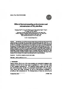
Tempering is the key step of the TMT to achieve the optimum precipitate size, and the recovery degree of the martensitic matrix that guarantees the optimal combination of toughness and creep strength properties. As commercially used for this steel grade, a tempering temperature of 740 ◦ C and a holding time of 45 min were selected in this work. To understand the effect of the TMT applied, the number density and average size of precipitates were calculated analyzing at least 100 precipitates for MX from TEM micrographs and 300 M23 C6 from SEM micrographs. As shown in Table 5, the ausforming treatment does not produce a significant change in size and distribution of the M23 C6 . The precipitation processes of these carbides take place on prior austenite grain, block, and lath boundaries as soon as the tempering begins, and it is completed in a short time [26] (Figure 9a,b,d,e). The lath refinement produced during ausforming can increase the number of potential nucleation sites for these precipitates on lath boundaries. By contrast, greater block width and prior austenite grain is obtained after TMT. Since M23 C6 precipitates nucleate first on prior austenite grain and block boundaries due to its higher energy, the remaining carbon content will precipitate as M23 C6 on lath boundaries obtaining finer M23 C6 distribution in TMT samples. This difference in size between the M23 C6 formed on lath boundaries, and those nucleated on block and prior austenite grain boundaries, may produce a faster Ostwald ripening coarsening resulting in an average M23 C6 size and number density similar to the G91 in as-received condition. Besides, the number density of MX precipitates in the TMT samples increases in three orders of magnitude, having a size about four times smaller than those in the G91 in as-received condition, which is in good agreement with previous works where similar thermomechanical treatment were applied in G91 [8,14] (Figure 9c,f). The higher austenitization temperature and ausforming processing greatly increased the dislocation density in austenite as others author have demonstrated in previous works [27], resulting in a higher number of nucleation sites for precipitation of MX precipitates inside the martensite laths. Thus, the higher dislocation density introduced by deformation at 600 ◦ C is responsible for a smaller size of these precipitates and the slightly higher number density. Partial recrystallization during ausforming at 900 ◦ C causes a significant decrease in dislocation density in recrystallized grains as well as an inhomogeneous distribution of MX precipitate.
Metals 2017, 7, 236
9 of 11
Table 5. Number density and size of precipitates after TMT and G91 in as-received condition. Sample
Precipitate
Diameter (nm)
Number Density (m−3 )
G91 as-received
M23 C6 MX
141 ± 4 25 ± 0.6
6.2019 8.141019
Def. at 900 ◦ C
M23 C6 MX
125 ± 3 7.4 ± 0.3
8.501019 6.41022
Def. at 600 ◦ C
M23 C6 MX
136 ± 5 5.59 ± 0.4
3.781019 9.391022
Metals 2017, 7, 236
9 of 11
(a)
(b)
(c)
(d)
(e)
(f)
Figure 9. (a) SEM micrograph showing M23C6 on grain boundaries and TEM micrographs showing, Figure 9. (a) SEM micrograph showing M23 C6 on grain boundaries and TEM micrographs showing, (b) M23C6 on lath boundaries, and (c) MX within laths for the sample after TMT (ausformed at 600 (b) M23 C6 on lath boundaries, and (c) MX within laths for the sample after TMT (ausformed at 600 ◦ C); °C); and (d) SEM micrograph and TEM micrographs showing (e) M23C6 on lath boundaries and (f) and (d) SEM micrograph and TEM micrographs showing (e) M23 C6 on lath boundaries and (f) MX MX within laths for the sample after TMT (ausformed at ◦900 °C). within laths for the sample after TMT (ausformed at 900 C). Table 5. Number density and size of precipitates after TMT and G91 in as-received condition.
Hardness measurements were performed in the G91 in as-received condition and−3 after TMTs Sample Precipitate Diameter (nm) Number Density (m ) (Table 6). The samples after TMTs show values 141 up ±to4 50 HV5 higher than M23Chardness 6 6.2019the ones for G91 in G91 as-received as-received condition, being the values for the TMT samples very similar. These results together with 19 MX 25 ± 0.6 8.1410 19 the microstructural characterization M carried out demonstrate in strength after TMT, 23C6 125 ± 3the improvement 8.5010 Def. at 900 °C MX along with the 7.4increase ± 0.3 6.41022 and reduction in which is attributable to the lath refinement in number density 136 ± 5 3.781019 M23C6 size of MX precipitates. Def. at 600 °C MX
5.59 ± 0.4
9.391022
Table 6. Hardness values for the sample after TMT and G91 in as-received condition.
Hardness measurements were performed in the G91 in as-received condition and after TMTs ◦ C than the ones for G91 (Table 6). The samples G91 afteras-Received TMTs show hardness 50 HV5 higher Def. atvalues 900 ◦ Cup toDef. at 600 in as-received condition, being the values for the TMT samples very similar. These results together 260 ± 2 310 ± 9 307 ± 8 with the microstructural characterization carried out demonstrate the improvement in strength after TMT, which is attributable to the lath refinement along with the increase in number density and 4. Conclusions reduction in size of MX precipitates.
The microstructural analyses carried out allow us to conclude that applying a TMT instead of Tabletreatment 6. Hardnesson values the sample after TMT andwill G91 promote: in as-received condition. conventional heat G91 for ferritic/martensitic steel G91 as-Received 260 ± 2
Def. at 900 °C 310 ± 9
Def. at 600 °C 307 ± 8
4. Conclusions The microstructural analyses carried out allow us to conclude that applying a TMT instead of
Metals 2017, 7, 236
1. 2. 3.
10 of 11
Microstructures containing three orders of magnitude higher number density and four times smaller size of MX precipitates. Microstructures contain M23 C6 precipitates with very similar values of size and number density. An increase in hardness of 50 HV5, which is attributable to the increase in the number density and the reduction in the size of MX nanoprecipitates and the lath width refinement.
The main conclusions reached on the effect of ausforming on the martensitic microstructure are summarized below: 4.
5.
The martensitic microstructure reduces its lath width due to the strengthening of austenite produced by ausforming. However, ausforming at 600 ◦ C results in a higher block width as compared to ausfoming at 900 ◦ C because of the variant selection that takes place during the martensitic transformation in the sample ausformed at 600 ◦ C. The ausforming temperature does not affect M23 C6 distribution and size, but ausforming at 600 ◦ C leads to a slightly smaller size of MX.
Acknowledgments: The authors acknowledge financial support to Spanish Ministerio de Economia y Competitividad (MINECO) in the form of a Coordinate Project (MAT2016-80875-C3-1-R). The work presented here is done within the Joint Program on Nuclear Materials of the European Energy Research Alliance Pilot Project CREMAR. The authors also would like to acknowledge financial support to Comunidad de Madrid through DIMMAT-CM_S2013/MIT-2775 project. The authors are grateful to Javier Vara, Alberto Delgado, and Alberto López for the experimental support. Javier Vivas acknowledges financial support in the form of a FPI Grant BES-2014-069863. Author Contributions: All authors were involved in discussing the results and in finalizing the manuscript. Conflicts of Interest: The authors declare no conflict of interest.
References 1. 2. 3. 4. 5. 6.
7. 8. 9.
10. 11.
Mayer, K.H.; Masuyama, F. The development of creep-resistant steels. In Creep-Resistant Steels; Woodhead Publishing: Cambridge, UK, 2008; pp. 15–77. Klueh, R.L.; Gelles, D.S.; Jitsukawa, S.; Kimura, A.; Odette, G.R.; van der Schaaf, B.; Victoria, M. Ferritic/martensitic steels—Overview of recent results. J. Nucl. Mater. 2002, 307, 455–465. [CrossRef] Klueh, R.L.; Ehrlich, K.; Abe, F. Ferritic/martensitic steels: Promises and problems. J. Nucl. Mater. 1992, 191, 116–124. Helis, L.; Toda, Y.; Hara, T.; Miyazaki, H.; Abe, F. Effect of cobalt on the microstructure of tempered martensitic 9Cr steel for ultra-supercritical power plants. Mater. Sci. Eng. A 2009, 510, 88–94. [CrossRef] Kipelova, A.; Kaibyshev, R.; Belyakov, A.; Molodov, D. Microstructure evolution in a 3% co modified P911 heat resistant steel under tempering and creep conditions. Mater. Sci. Eng. A 2011, 528, 1280–1286. [CrossRef] Kneževi´c, V.; Balun, J.; Sauthoff, G.; Inden, G.; Schneider, A. Design of martensitic/ferritic heat-resistant steels for application at 650 ◦ C with supporting thermodynamic modelling. Mater. Sci. Eng. A 2008, 477, 334–343. [CrossRef] Rojas, D.; Garcia, J.; Prat, O.; Sauthoff, G.; Kaysser-Pyzalla, A.R. 9%Cr heat resistant steels: Alloy design, microstructure evolution and creep response at 650 ◦ C. Mater. Sci. Eng. A 2011, 528, 5164–5176. [CrossRef] Klueh, R.L.; Hashimoto, N.; Maziasz, P.J. Development of new nano-particle-strengthened martensitic steels. Scr. Mater. 2005, 53, 275–280. [CrossRef] Hollner, S.; Fournier, B.; Le Pendu, J.; Cozzika, T.; Tournié, I.; Brachet, J.C.; Pineau, A. High-temperature mechanical properties improvement on modified 9Cr–1mo martensitic steel through thermomechanical treatments. J. Nucl. Mater. 2010, 405, 101–108. [CrossRef] Tan, L.; Busby, J.T.; Maziasz, P.J.; Yamamoto, Y. Effect of thermomechanical treatment on 9Cr ferritic–martensitic steels. J. Nucl. Mater. 2013, 441, 713–717. [CrossRef] Hollner, S.; Piozin, E.; Mayr, P.; Caës, C.; Tournié, I.; Pineau, A.; Fournier, B. Characterization of a boron alloyed 9Cr3W3CoVNbBN steel and further improvement of its high-temperature mechanical properties by thermomechanical treatments. J. Nucl. Mater. 2013, 441, 15–23. [CrossRef]
Metals 2017, 7, 236
12. 13. 14. 15.
16. 17. 18. 19. 20. 21.
22. 23. 24.
25. 26.
27.
11 of 11
Abe, F. Precipitate design for creep strengthening of 9% Cr tempered martensitic steel for ultra-supercritical power plants. Sci. Technol. Adv. Mater. 2008, 9, 013002. [CrossRef] [PubMed] Maruyama, K.; Sawada, K.; Koike, J.I. Strengthening mechanisms of creep resistant tempered martensitic steel. ISIJ Int. 2001, 41, 641–653. [CrossRef] Klueh, R.L.; Hashimoto, N.; Maziasz, P.J. New nano-particle-strengthened ferritic/martensitic steels by conventional thermo-mechanical treatment. J. Nucl. Mater. 2007, 367, 48–53. [CrossRef] Li, S.; Eliniyaz, Z.; Sun, F.; Shen, Y.; Zhang, L.; Shan, A. Effect of thermo-mechanical treatment on microstructure and mechanical properties of p92 heat resistant steel. Mater. Sci. Eng. A 2013, 559, 882–888. [CrossRef] Abe, F. Coarsening behavior of lath and its effect on creep rates in tempered martensitic 9Cr-W steels. Mater. Sci. Eng. A 2004, 387, 565–569. [CrossRef] Tamura, M.; Sakasegawa, H.; Kohyama, A.; Esaka, H.; Shinozuka, K. Effect of mx type particles on creep strength of ferritic steel. J. Nucl. Mater. 2003, 321, 288–293. [CrossRef] Tan, L.; Byun, T.S.; Katoh, Y.; Snead, L.L. Stability of mx-type strengthening nanoprecipitates in ferritic steels under thermal aging, stress and ion irradiation. Acta Mater. 2014, 71, 11–19. [CrossRef] Kimura, K.; Sawada, K.; Kushima, H.; Toda, Y. Influence of chemical composition and heat treatment on long-term creep strength of grade 91 steel. Procedia Eng. 2013, 55, 2–9. [CrossRef] Klueh, R.L. Elevated temperature ferritic and martensitic steels and their application to future nuclear reactors. Int. Mater. Rev. 2005, 50, 287–310. [CrossRef] Caballero, F.G.; Roelofs, H.; Hasler, S.; Capdevila, C.; Chao, J.; Cornide, J.; Garcia-Mateo, C. Influence of bainite morphology on impact toughness of continuously cooled cementite free bainitic steels. Mater. Sci. Technol. 2012, 28, 95–102. [CrossRef] Shi, Z.; liu, K.; Wang, M.; Shi, J.; Dong, H.; Pu, J.; Chi, B.; Zhang, Y.; Jian, L. Effect of tensile deformation of austenite on the morphology and strength of lath martensite. Met. Mater. Int. 2012, 18, 317–320. [CrossRef] Miyamoto, G.; Iwata, N.; Takayama, N.; Furuhara, T. Variant selection of lath martensite and bainite transformation in low carbon steel by ausforming. J. Alloys Compd. 2013, 577, S528–S532. [CrossRef] Zhang, M.; Wang, Y.H.; Zheng, C.L.; Zhang, F.C.; Wang, T.S. Austenite deformation behavior and the effect of ausforming process on martensite starting temperature and ausformed martensite microstructure in medium-carbon si–al-rich alloy steel. Mater. Sci. Eng. A 2014, 596, 9–14. [CrossRef] Chatterjee, S.; Wang, H.S.; Yang, J.R.; Bhadeshia, H.K.D.H. Mechanical stabilisation of austenite. Mater. Sci. Technol. 2006, 22, 641–644. [CrossRef] Prat, O.; García, J.; Rojas, D.; Sanhueza, J.P.; Camurri, C. Study of nucleation, growth and coarsening of precipitates in a novel 9%Cr heat resistant steel: Experimental and modeling. Mater. Chem. Phys. 2014, 143, 754–764. [CrossRef] Seo, S.W.; Jung, G.S.; Lee, J.S.; Bae, C.M.; Bhadeshia, H.K.D.H.; Suh, D.W. Ausforming of medium carbon steel. Mater. Sci. Technol. 2015, 31, 436–442. [CrossRef] © 2017 by the authors. Licensee MDPI, Basel, Switzerland. This article is an open access article distributed under the terms and conditions of the Creative Commons Attribution (CC BY) license (http://creativecommons.org/licenses/by/4.0/).